Flexicon BULK-OUT BFC User manual

FLEXICONBULK-OUT®
Bulk Bag Discharger
Models: BFC, BFF & BFH
Installation and Operation Manual

FLEXICON®BULK-OUT®Bulk Bag Discharger Installation and Operation Manual - 1 -
FLEXICON CORPORATION 2400 Emrick Boulevard ■ Bethlehem, PA 18020-8006 USA
Tel: 1-888-FLEXICON ■ Tel: 1-610-814-2400 ■ Fax: 1-610-814-0600 ■ www.flexicon.com
Copyright 2003 FLEXICON®
FOREWORD
Thank you for purchasing a BULK-OUT®Bulk Bag Discharger from FLEXICON®. Please refer to the
following instructions for installing and operating your FLEXICON®Bulk Bag Discharger system. If
you encounter any problems which prevent safe reliable installation and / or operation of the system,
please call the FLEXICON® service department immediately to address any concerns you may have.
The BULK-OUT®Bulk Bag Discharger appearance may be slightly different than the details depicted
in this manual. Any differences do not affect the function, designed capacity, or operation of the
equipment.
FLEXICONCorporation has made every effort to ensure the accuracy and validity of this document
however errors and omissions may have occurred. If an error or omission is found, please contact
FLEXICONCorporation.
No part of this publication may be distributed, reproduced or transmitted in any form without the
written permission of the FLEXICONCorporation.
Familiarity with Manual and Regulations
In order for this machine to be installed, operated, cleaned & maintained safely, all of the provisions
of this manual and all other applicable codes and regulations, some of which have been referred to
herein, must be strictly adhered to. Codes and regulations enacted to protect personnel from hazard
of injury may change from time to time. It is the customer’s responsibility to remain familiar with, and
to comply with all codes, and regulations related to this equipment or its use. It is also the customer’s
responsibility to teach its employees how to operate the equipment properly, including how to
recognize and avoid risks. All personnel who will be involved in installing, operating, cleaning or
maintaining the system should be given a copy of this manual to read, and follow.
Documentation Package
Each bulk material handling system from Flexicon®is supplied with a USB Flash Drive containing a
Documentation Package that was specifically prepared for the equipment provided. This Flash Drive
contains manuals, drawings, schematics, video clips and spare parts lists that will be a useful
reference for proper installation, operation, and maintenance of your system. If you cannot locate
this Flash Drive then please see the Contacting FLEXICON®page of this manual for the telephone
number and the information required to identify your material handling system and its components.

FLEXICON®BULK-OUT®Bulk Bag Discharger Installation and Operation Manual - 2 -
FLEXICON CORPORATION 2400 Emrick Boulevard ■ Bethlehem, PA 18020-8006 USA
Tel: 1-888-FLEXICON ■ Tel: 1-610-814-2400 ■ Fax: 1-610-814-0600 ■ www.flexicon.com
Copyright 2003 FLEXICON®
TABLE OF CONTENTS
TABLE OF FIGURES 3
CONTACTING FLEXICON®
Telephone and Fax Numbers 4
Hours of Operation 4
System Identification 4
INTRODUCTION
Safety Terms & Summary 5
Equipment Safety Warnings 6
Applicable FLEXICON®Equipment 7
INSTALLATION
Standing up the Base Frame 9
Locating the Base Frame 10
Anchoring the Base Frame 10
Assembling the BFF Frame 11
Assembling the BFC Frame 12
Electric Hoist Wiring 15
Pneumatic Hoist Air Connection 15
OPERATION
Connection of bulk bag Loops to Z-CLIP™16
Connection of bulk bag Liner 16
Loading a bulk bag into a BFF Frame 17
Loading a bulk bag into a BFC Frame 17
OPTIONAL EQUIPMENT
FLOW-FLEXER®Bulk Bag Agitation Device 19
Operation 19
Adjustment 20
Load Cells 20
POP-TOP®Bulk Bag Elongation Option (BFF only) 21
Power-Cincher®Flow Control Valve 22
TELE-TUBE®Telescoping Tube 22
CVD Interface with Iris Valve 22
CVD Operation 22
MAINTENANCE
Maintenance Instructions 23
LONG TERM STORAGE 24
SPARE PARTS 25

FLEXICON®BULK-OUT®Bulk Bag Discharger Installation and Operation Manual - 3 -
FLEXICON CORPORATION 2400 Emrick Boulevard ■ Bethlehem, PA 18020-8006 USA
Tel: 1-888-FLEXICON ■ Tel: 1-610-814-2400 ■ Fax: 1-610-814-0600 ■ www.flexicon.com
Copyright 2003 FLEXICON®
TABLE OF FIGURES
Figure 1: Sample Serial Number Nameplate 4
Figure 2: Base Frame Arrangement 10
Figure 3: BFF Frame Arrangement 11
Figure 4: BFC Frame Arrangement 12
Figure 5: BFC Hoist I-Beam Assembly 14
Figure 6: BFC Hoist Festooning Assembly 15
Figure 7: Z-CLIP™Bag Loop Retainer 16
Figure 8: Bag Loop Location in Z-CLIP™16
Figure 9: Bag Liner Clamp Connection 16
Figure 10: Bag Lift Position 18
Figure 11: Bag Lift Frame Orientation 18
Figure 12: Swaying Bulk Bag 18
Figure 13: FLOW-FLEXER®Arrangement 19
Figure 14: FLOW-FLEXER®Assembly 20
Figure 15: Assembly of POP-TOP®Extension Arms 21
Figure 16: CVD Interface with Iris valve 22
FLEXICON®BULK-OUT®Bulk Bag Discharger Installation and Operation Manual - 4 -
FLEXICON CORPORATION 2400 Emrick Boulevard ■ Bethlehem, PA 18020-8006 USA
Tel: 1-888-FLEXICON ■ Tel: 1-610-814-2400 ■ Fax: 1-610-814-0600 ■ www.flexicon.com
Copyright 2003 FLEXICON®
CONTACTING FLEXICON
Telephone and Fax Numbers
Phone: 1-888-FLEXICON[1-888-353-9426]
610-814-2400
Fax: 610-814-0600
FlexiconOfficial Site: www.flexicon.com
Flexicon Parts Department:
Phone: 610-814-2400 ext. 10660 or 10692
Email: [email protected]
Hours of Operation
Monday through Friday 8:00 am to 5:00 pm E.S.T.
System Identification
The system will have a Serial Number nameplate similar to the example below that will be attached to
the equipment near the base in the operator access point.
Figure 1: Sample Serial Number Nameplate
12345
FLEXICON®BULK-OUT®Bulk Bag Discharger Installation and Operation Manual - 5 -
FLEXICON CORPORATION 2400 Emrick Boulevard ■ Bethlehem, PA 18020-8006 USA
Tel: 1-888-FLEXICON ■ Tel: 1-610-814-2400 ■ Fax: 1-610-814-0600 ■ www.flexicon.com
Copyright 2003 FLEXICON®
INTRODUCTION
Safety Terms and Summary
This manual provides important information for personnel involved in the installation, operation, and
maintenance of this product. Even though you may be familiar with this, or similar equipment, it is
highly recommended that you read this manual before installing, operating, or maintaining this
particular equipment.
Throughout this manual there are steps and procedures that can present hazardous situations. The
following words are used to identify the degree or level of hazard seriousness.
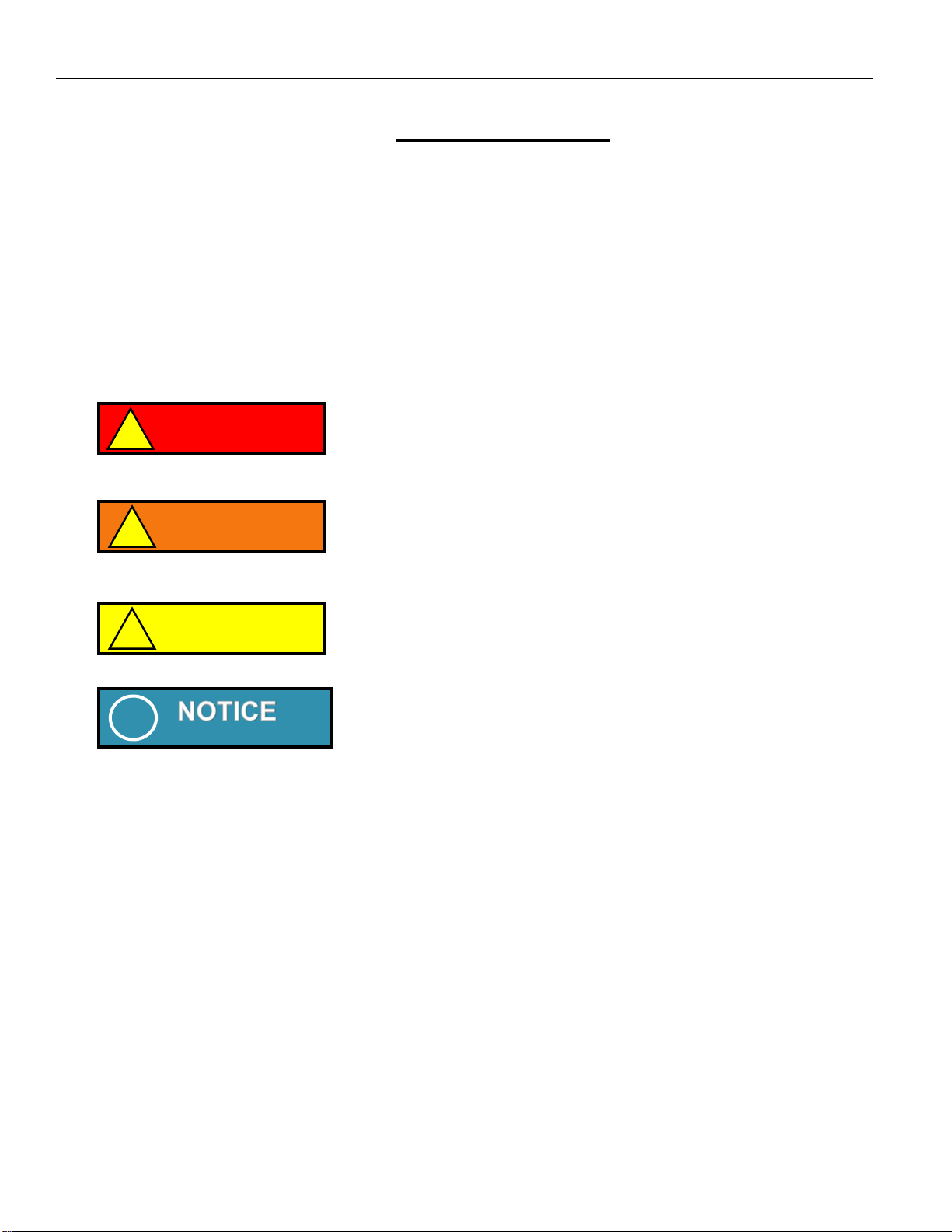
Notice is used to notify people of installation, operation,
or maintenance information which is important but not
directly hazard-related.
Danger indicates an imminently hazardous situation
which, if not avoided, will result in death or serious
injury, and property damage.
Warning indicates an imminently hazardous situation which, if
not avoided, could result in death or serious injury, and
property damage.
Caution indicates a potentially hazardous situation
which, if not avoided, may result in minor or moderate
injury, or property damage.
!
CAUTION
!
DANGER
!
WARNING
!
!

FLEXICON®BULK-OUT®Bulk Bag Discharger Installation and Operation Manual - 6 -
FLEXICON CORPORATION 2400 Emrick Boulevard ■ Bethlehem, PA 18020-8006 USA
Tel: 1-888-FLEXICON ■ Tel: 1-610-814-2400 ■ Fax: 1-610-814-0600 ■ www.flexicon.com
Copyright 2003 FLEXICON®
Equipment Safety Warnings
Please read this section prior to installing your system.
Locating and installing the FLEXICON® BULK-OUT®Bulk Bag Discharger is a very important step in
the correct and efficient use of this equipment. We recommend that you follow these procedures to
achieve complete satisfaction.
FLEXICON® BULK-OUT®Bulk Bag Discharger Base Frames are supplied factory assembled. If in a
rare occasion it has been supplied unassembled contact Flexicon for more information.
Do not use the FLEXICON® BULK-OUT®Bulk
Bag Discharger for materials other than which it
was specified for. If you wish to add new
materials please consult with FLEXICON®before
doing so.
Make sure the vent tube on the hopper cover, if
supplied, is fitted with a filter sock before
discharging a Bulk bag.
Do not mount peripheral equipment on the Bulk
bag Frame.
Do not allow individuals to stand on any part of
the frame or under any bulk bags as they are
being loaded or unloaded.
DANGER
!
Do not allow tools, rags, bags (other than Bulk
bags called for in the specifications) to remain in
or enter the system during its operation.
Do not allow agglomerating or hygroscopic
material to remain in the FLEXICON®BULK-
OUT®Bulk Bag Discharger for extended periods
of time. These materials may tend to set up or
become hard making it difficult to discharge the
Bulk bag.
DANGER
For jobs installed in any classified hazardous areas
ensure the system is fully grounded before use.
!!
!
Periodically check that all bolted connections
are tight, as they might become loose in transit
or during operation.
CAUTION
!
CAUTION
!
DANGER
!
DANGER
!
!
!
!
!
!
FLEXICON®BULK-OUT®Bulk Bag Discharger Installation and Operation Manual - 7 -
FLEXICON CORPORATION 2400 Emrick Boulevard ■ Bethlehem, PA 18020-8006 USA
Tel: 1-888-FLEXICON ■ Tel: 1-610-814-2400 ■ Fax: 1-610-814-0600 ■ www.flexicon.com
Copyright 2003 FLEXICON®
Applicable FLEXICON®Equipment
Equipment
Model
Reference
Overview
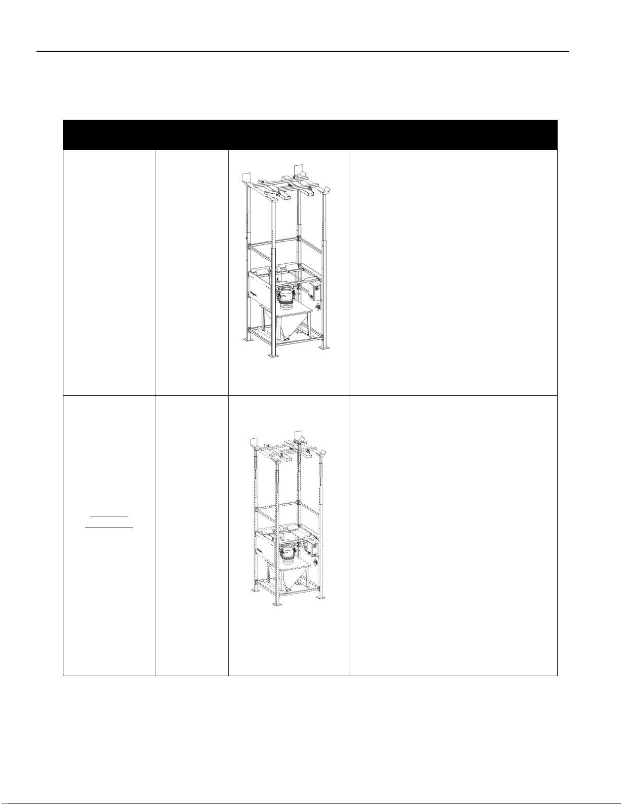
BULK-OUT®
Bulk Bag
Discharger
BFF
BFF-X-X
Front View
The BFF BULK-OUT®Bulk Bag
Discharger incorporates a
forkliftable bulk bag lifting frame
which facilitates loading of the bulk
bag into the frame as well as
support it during the emptying
process. The BFF includes four
independent, adjustable extension
arms which accommodate bags
weighing up to 4000lb and ranging
from 36”to 84” high with a maximum
width of 36” at the bag seam and
48” at the widest parts when full.
Optional
Equipment
POP-TOP®
PTP-X
Front View
This option replaces the standard
extension arms with periscoping
extension arms that incorporate a
gas spring mounted inside each.
These four independent, adjustable,
periscoping extension arms
compensate for bulk bag elongation
during the emptying process. As the
weight of the material in the bulk
bag decreases, the arms
compensate by raising the bag lifting
frame that is attached to the straps
of the bulk bag. The POP-TOP®
accommodates bags weighing up to
4000lb and ranging from 36” to 84”
high with a maximum width of 36” at
the bag seam and 48” at the widest
parts when full.
FLEXICON®BULK-OUT®Bulk Bag Discharger Installation and Operation Manual - 8 -
FLEXICON CORPORATION 2400 Emrick Boulevard ■ Bethlehem, PA 18020-8006 USA
Tel: 1-888-FLEXICON ■ Tel: 1-610-814-2400 ■ Fax: 1-610-814-0600 ■ www.flexicon.com
Copyright 2003 FLEXICON®
Equipment
Model
Reference
Overview
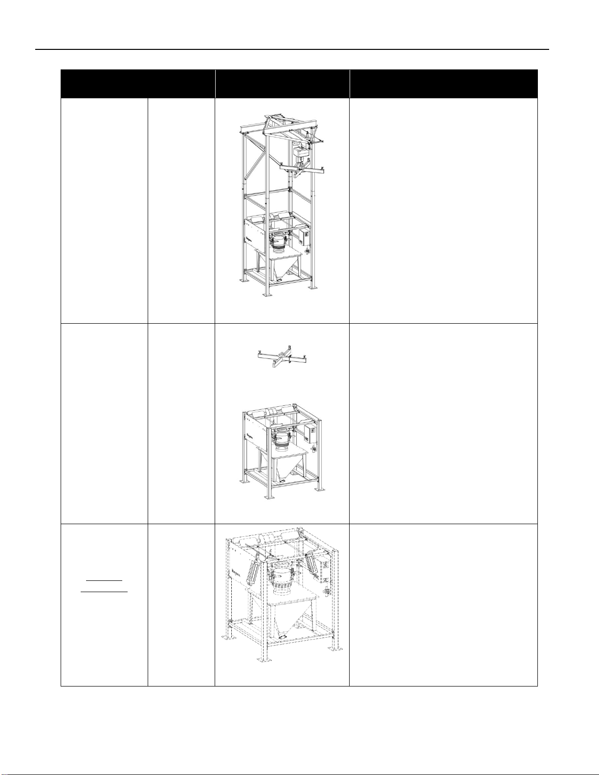
BULK-OUT®
Bulk Bag
Discharger
BFC
BFC-X-X
Front View
The BFC BULK-OUT®Bulk Bag
Discharger incorporates a
cantilevered I-beam with a
powered hoist and trolley to lift
and position a bulk bag into the
frame. The BFC frame, hoist &
trolley, and lifting frame
accommodate bags weighing up
to 3200lb and ranging from 36” to
72” high with a maximum width of
36” at the bag seam and 48” at
the widest parts when full.
BULK-OUT®
Bulk Bag
Discharger
BFH
BFH-X-X
Front View
The BFH BULK-OUT®Bulk Bag
Discharger requires a customer
supplied lifting mechanism to
elevate and suspend a bulk bag
over the frame. The BFH
includes a standard hoist style
bag lifting frame and a safety
frame with all provisions for
mounting a FLOW-FLEXER®. It
is designed for a maximum
3200lb capacity bulk bag with a
maximum width of 36” at the bag
seam and 48” at the widest point
when full.
Optional
Equipment
FLOW-FLEXER®
Bulk Bag
Agitation Device
FFX-XX
Front View
The FLOW-FLEXER®Bulk Bag
Agitation Device is designed to
increase bulk bag discharge for
difficult, semi to non-free flowing
materials. Two pneumatically
driven ‘paddles’ raise and lower
the bottom edges of a bulk bag to
direct material into the bag outlet
spout. They also raise the bag
into a steep ‘V’ shape to promote
total evacuation of material.
FLEXICON®BULK-OUT®Bulk Bag Discharger Installation and Operation Manual - 9 -
FLEXICON CORPORATION 2400 Emrick Boulevard ■ Bethlehem, PA 18020-8006 USA
Tel: 1-888-FLEXICON ■ Tel: 1-610-814-2400 ■ Fax: 1-610-814-0600 ■ www.flexicon.com
Copyright 2003 FLEXICON®
INSTALLATION
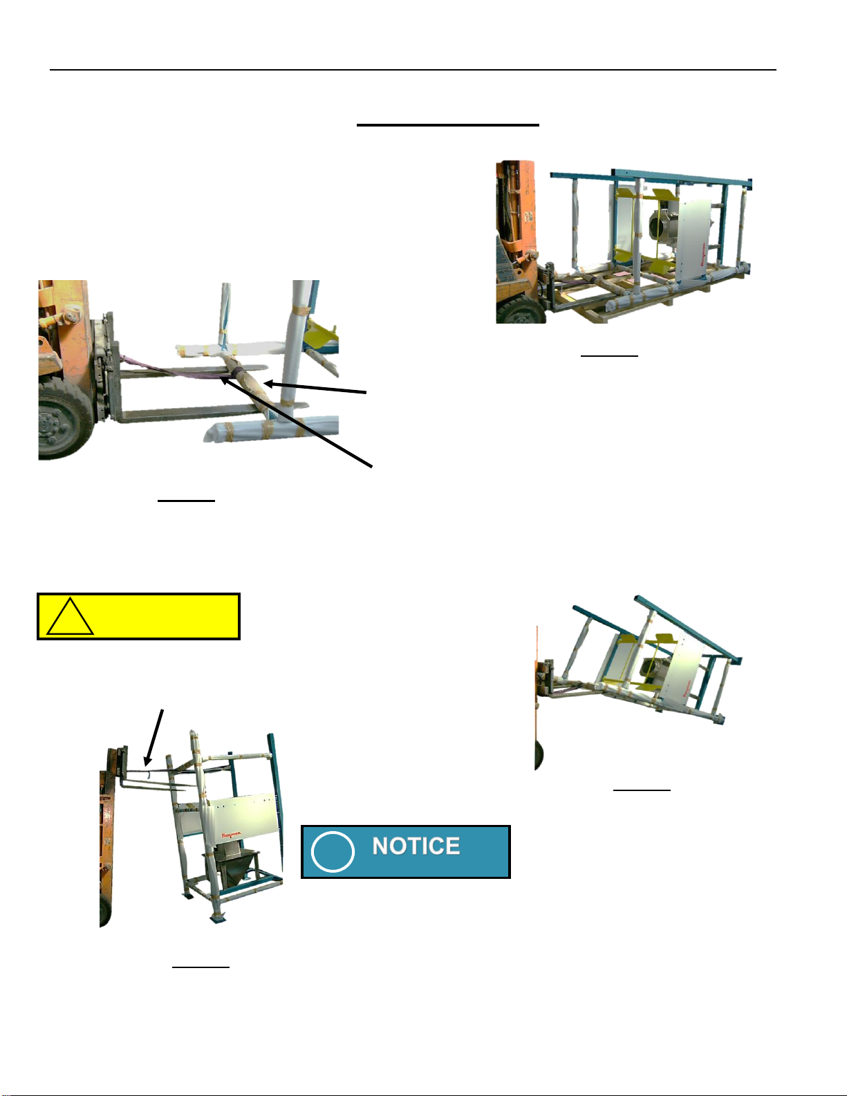
Standing up the base frame
Once the frame is standing upright
it is important to note the
orientation of operator access and
bag load side. With a standard
configuration the bulk bag is
loaded from the same side as
operator access.
Ensure that a safety strap is attached to the frame
and the fork lift. It must be at located at least 12
inches SHORTER than the fork length to assure
the frame will be secured to the fork lift truck.
Use a suitable fork lift truck that is capable of lifting to
a height of no less than 8 feet. Raise both ends of the
frame just enough to slide out the pallet.
Insert Forks centrally under the horizontal cross
bar that is opposite the foot pads as shown.
Avoid making contact with the Safety Frame.
Raise forks while driving forward slowly until
the balance point is reached.
STEP 1
STEP 3
STEP 2
STEP 4
Keep moving forward slowly and
beware that frame will swing
forward. Avoid a rapid descent.
CAUTION
!
The strap will hold the frame from dropping too rapidly.
!
FLEXICON®BULK-OUT®Bulk Bag Discharger Installation and Operation Manual - 10 -
FLEXICON CORPORATION 2400 Emrick Boulevard ■ Bethlehem, PA 18020-8006 USA
Tel: 1-888-FLEXICON ■ Tel: 1-610-814-2400 ■ Fax: 1-610-814-0600 ■ www.flexicon.com
Copyright 2003 FLEXICON®
Locating the Base Frame
Ensure that the foundations are suitable to withstand the full load of the frame. If applicable, see the
Load Cell information located in the ‘Optional Equipment’ section of this manual.
Anchoring the Base Frame
Anchor the base frame to the foundation using the appropriate SAE Grade 5 (or better) hardware.
Flexicon®recommends that the customer consults with a civil engineer or local professional engineer
to evaluate floor substrates and specify the type and depth of floor anchors required. (16)
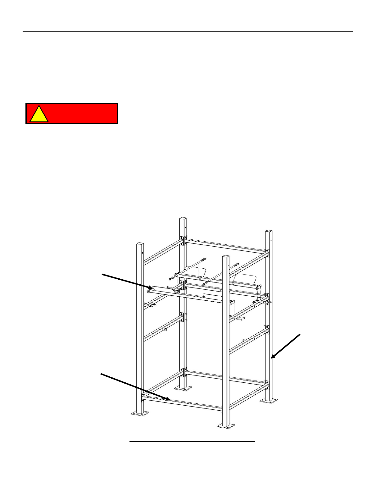
bolts/anchors are typically needed.A standard FLEXICON® BULK-OUT®Bulk Bag Discharger base
frame is shown below in Figure 6. It can be assembled into either a BFC or BFF Frame. There is a
removable cross brace on the operator access side which can be unbolted and removed temporarily
to allow for easier installation of other components that are to be located inside the frame such as a
floor hopper or similar items. The brace is to be bolted back in place after the component(s) has
been installed inside the frame.
Figure 2: Base Frame Arrangement
Safety
Frame
Standard
Base Frame
Once the Base Frame is located it must then be anchored to
the foundation using the appropriate hardware. Failure to
do so could result in the frame tipping over.
DANGER
!
Removable
Brace
FLEXICON®BULK-OUT®Bulk Bag Discharger Installation and Operation Manual - 11 -
FLEXICON CORPORATION 2400 Emrick Boulevard ■ Bethlehem, PA 18020-8006 USA
Tel: 1-888-FLEXICON ■ Tel: 1-610-814-2400 ■ Fax: 1-610-814-0600 ■ www.flexicon.com
Copyright 2003 FLEXICON®
Assembling the BFF Frame
The POP-TOP®or Extension Arms are inserted into the Base Frame to the lowest height setting and
secured with (4) 5/8” diameter x 3 ½” long clevis pin/safety clips.
Note: there are (2) Rear Extension Arms (Left and Right) and (2) Front Extension Arms (Left and
Right) which must be positioned as shown in Figure 7.
The height of the Extension Arms are adjusted (in 2” increments) to accommodate the size of bulk
bag. The height is correctly set when the bottom of the bulk bag is 1” to 2” above the center of the
Safety Frame (with or without a FLOW-FLEXER®).
Figure 3: BFF Frame arrangement
BFF Forkliftable Bag
Lifting Frame
(2)-Rear
Extension Arms or
POP-TOP®
Extension Arm
(Left and Right)
Standard Base
Frame
(2)-Front
Extension Arms or
POP-TOP®
Extension Arm
(Left and Right)
(4) Receiving Cups
Safety Frame
(4) Clevis Pins /
Safety Clips
FLEXICON®BULK-OUT®Bulk Bag Discharger Installation and Operation Manual - 12 -
FLEXICON CORPORATION 2400 Emrick Boulevard ■ Bethlehem, PA 18020-8006 USA
Tel: 1-888-FLEXICON ■ Tel: 1-610-814-2400 ■ Fax: 1-610-814-0600 ■ www.flexicon.com
Copyright 2003 FLEXICON®
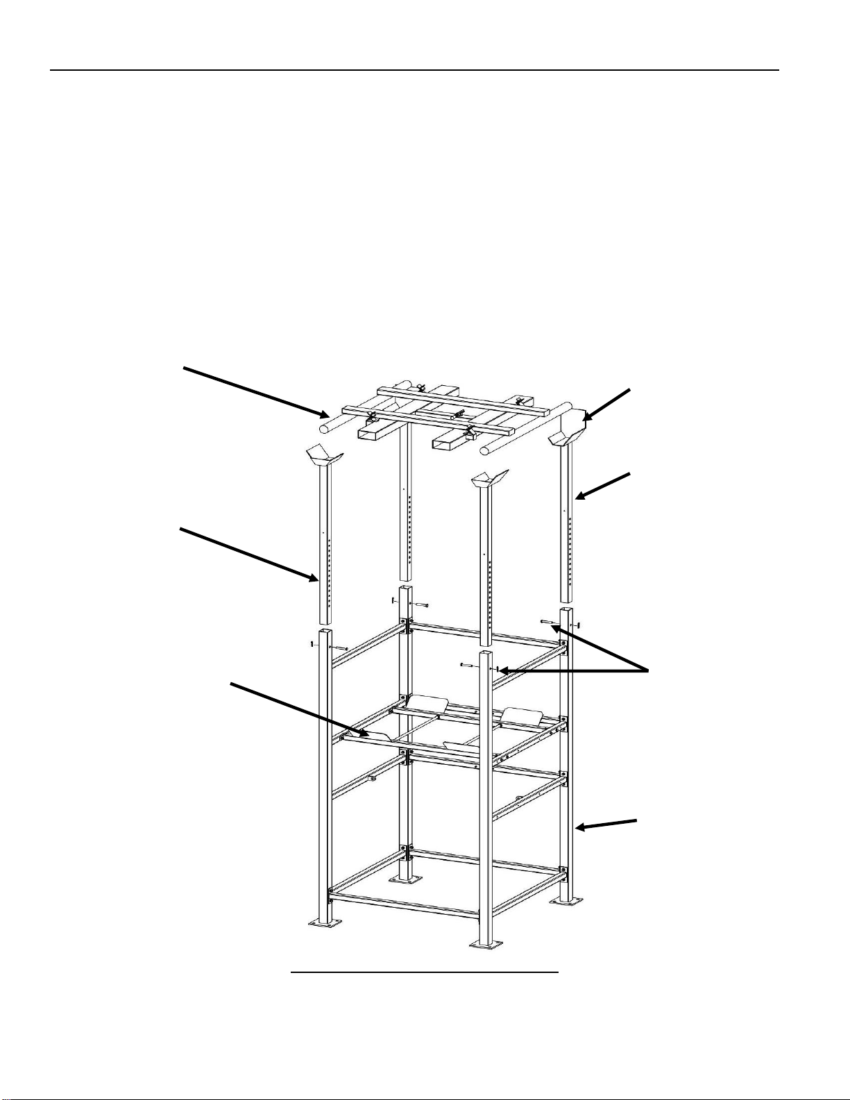
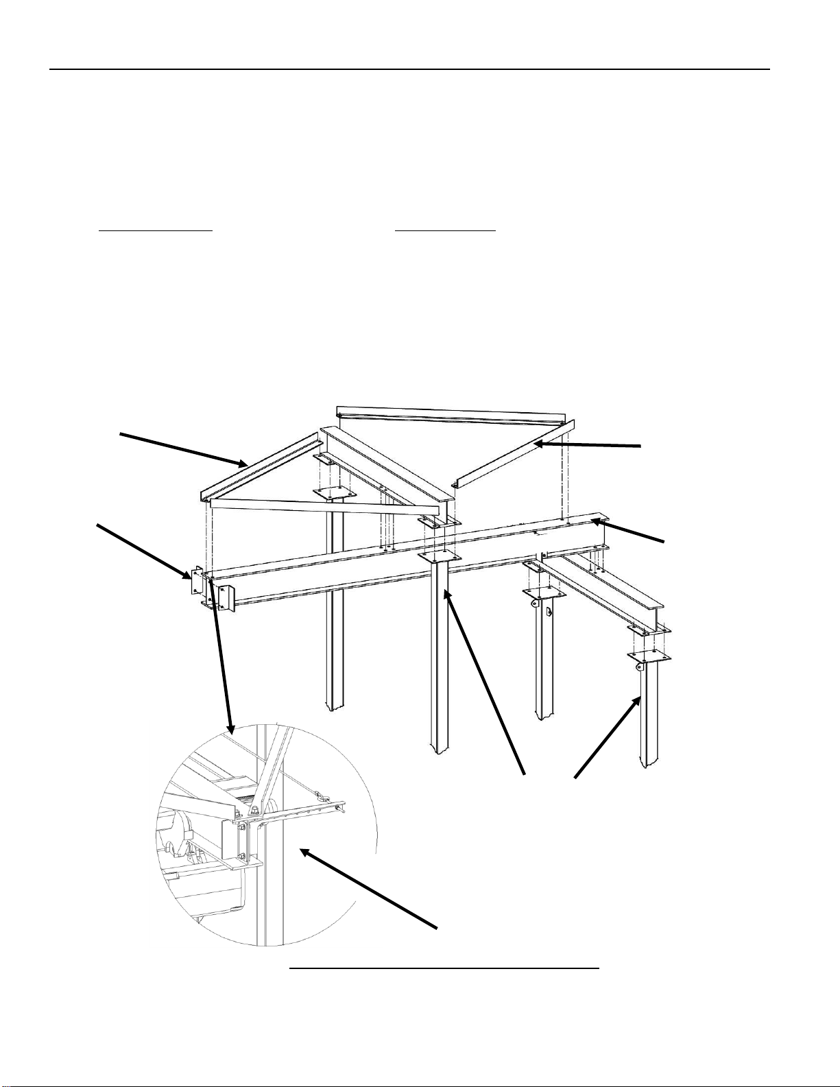
Assembling the BFC Frame
Figure 4: BFC Frame arrangement
Hoist I-Beam
Back Cross
Beam
(2)Rear
Extension Arms
(2)Horizontal Cross
Braces
(3) Diagonal
Cross Braces
(2)Front
Extension Arms
Front Cross
Beam

FLEXICON®BULK-OUT®Bulk Bag Discharger Installation and Operation Manual - 13 -
FLEXICON CORPORATION 2400 Emrick Boulevard ■ Bethlehem, PA 18020-8006 USA
Tel: 1-888-FLEXICON ■ Tel: 1-610-814-2400 ■ Fax: 1-610-814-0600 ■ www.flexicon.com
Copyright 2003 FLEXICON®
•Begin by installing the (4) extension arms (See Figure 4). There are (2) identical front
extension arms, (1) left hand back extension arm and (1) right hand back extension arm. The
front extension arms are longer than the rear arms and have only two tabs at the top. The
right hand back arm has two tabs 90 degrees opposed to each other at the bottom of the arm.
The left hand back arm has three tabs, one located at the bottom and the other two located at
the top which are 90 degrees opposed to each other.
•Assemble the arms in their respective legs. Be sure to orient them as shown in Figure 8.
Secure them in place with (1) 3/4”-10 bolt, (2) 3/4”-10 flat washers, (1) 3/4”-10 split lock washer
and (1) 3/4”-10 hex nut per leg. Torque the hardware to 130 ft/lbs for stainless steel and 270
ft/lbs for carbon steel.
•Assemble the back cross beam to the top of the rear extension arms (See Figure 5). Attach
using (8) 3/4”-10 bolts, (16) 3/4”-10 flat washers, (8) 3/4”-10 split lock washers and (8) 3/4”-10
hex nuts.
•Assemble the front cross beam to the top of the front extension arms (See Figure 5).
Assemble using (8) 3/4”-10 bolts, (16) 3/4”-10 flat washers, (8) 3/4”-10 split lock washers and
(8) 3/4”-10 hex nuts.
•Install both horizontal cross braces to the frame tabs provided using (4) 1/2”-13 bolts, (8) flat
washers, (4) split lock washers, and (4) 1/2”-13 hex nuts (See Figure 8).
•Install the (2) rear end stops onto the hoist beam using (2) 1/2”-13 bolts, (4) 1/2”-13 flat
washers, (2) 1/2”-13 split lock washer and (2) 1/2”-13 hex nuts.
•Assemble the hoist beam to the front and rear cross beams (See Figure 6).
•Assemble using (8) 3/4”-10 bolts, (16) 3/4”-10 flat washers (8) 3/4”-10 split lock washers and
(8) 3/4”-10 hex nuts.
•Assemble the (3) diagonal cross braces (see figure 3). The orientation of the braces will be
self-evident. Attach using (6) 1/2”-13 long bolts, (12) 1/2”-13 flat washers, (6) 1/2”-13 split lock
washer and (6) 1/2”-13 hex nuts.
•Assemble the (2) rear hoist beam braces which connect between the outside bolt on the front
cross beam/front extension arm assembly, to the holes provided on top of the hoist beam at
the back (See Figure 5). There is (1) left and (1) right hand rear hoist brace. There is an angle
cut on one end of each brace and it will be self-evident as to the proper orientation.
Throughout this entire procedure, whenever a connection is made with
either ½”-13 or ¾”-10 hardware, DO NOT fully tighten it to the final
torque spec unless otherwise specified. Thread the nut only to the point
where it engages the split lock washer then, using a wrench, tighten the
nut ½ turn! This allows for final alignment before tightening to final
torque.
!
FLEXICON®BULK-OUT®Bulk Bag Discharger Installation and Operation Manual - 14 -
FLEXICON CORPORATION 2400 Emrick Boulevard ■ Bethlehem, PA 18020-8006 USA
Tel: 1-888-FLEXICON ■ Tel: 1-610-814-2400 ■ Fax: 1-610-814-0600 ■ www.flexicon.com
Copyright 2003 FLEXICON®
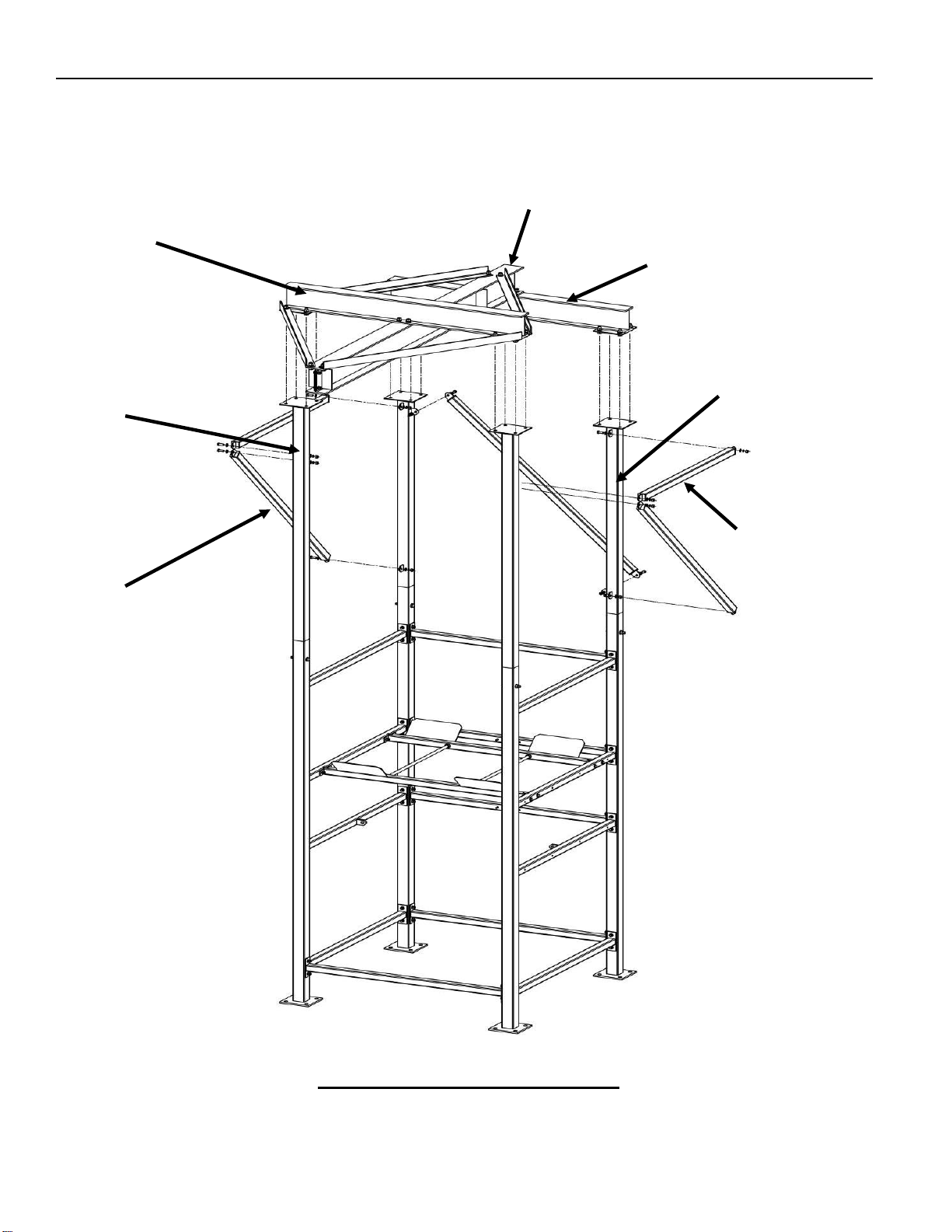
•Install the (2) front hoist beam braces to the top of the frame assembly in the same manner as
above (See Figure 5).
•Square the various components of the BFC upper section and tighten all hardware to the
following final torque specification:
Stainless Steel: Carbon Steel:
1/2”-13 to 40 ft/lbs 1/2”-13 to 75 ft/lbs
3/4”-10 to 130 ft/lbs 3/4”-10 to 270 ft/lbs
•Assemble the hoist onto the hoist beam as per the manufacturer’s manual supplied.
•Install the (2) front end stops onto the hoist beam using (2) 1/2”-13 bolts, (4) 1/2”-13 flat
washers, (2) 1/2”-13 split lock washer and (2) 1/2”-13 hex nuts.
Figure 5: BFC Hoist Beam Arrangement
Note bolt
orientation
(2) Rear
Hoist Beam
Braces
(2) Front
Hoist Beam
Braces
(2)End
Stops
Hoist Beam
Note height
difference between
extension arms

FLEXICON®BULK-OUT®Bulk Bag Discharger Installation and Operation Manual - 15 -
FLEXICON CORPORATION 2400 Emrick Boulevard ■ Bethlehem, PA 18020-8006 USA
Tel: 1-888-FLEXICON ■ Tel: 1-610-814-2400 ■ Fax: 1-610-814-0600 ■ www.flexicon.com
Copyright 2003 FLEXICON®
•Install the hoist festooning assembly as shown on Figure 6.
Electric Hoist Wiring
The main power cord for the hoist will require a connection to a customer supplied junction box that is
to be located on the back of the frame near the top. Note that with a standard hoist, FLEXICON®will
provide enough cord to be draped through the festooning cable assembly and extend to the back of
the frame near the top. Customer must run their main power supply to this location.
Pneumatic Hoist (Optional)
If your system is supplied with an optional pneumatic hoist it will require an air hose connection
directly into the hoist. FLEXICON®provides the festooning assembly only. The air connection for a
pneumatic hoist must include a customer supplied filter and lubricator installed between the air source
and air hose running to the hoist. (Where applicable see hoist manufacturer’s manual).
Hoist
Main Power Cord
Wire Rope
Tensioner
Wire Rope
Tensioner
Cable
Pulleys
Wire Rope
Figure 6: BFC Hoist Festooning Assembly
FLEXICON®BULK-OUT®Bulk Bag Discharger Installation and Operation Manual - 16 -
FLEXICON CORPORATION 2400 Emrick Boulevard ■ Bethlehem, PA 18020-8006 USA
Tel: 1-888-FLEXICON ■ Tel: 1-610-814-2400 ■ Fax: 1-610-814-0600 ■ www.flexicon.com
Copyright 2003 FLEXICON®
OPERATION
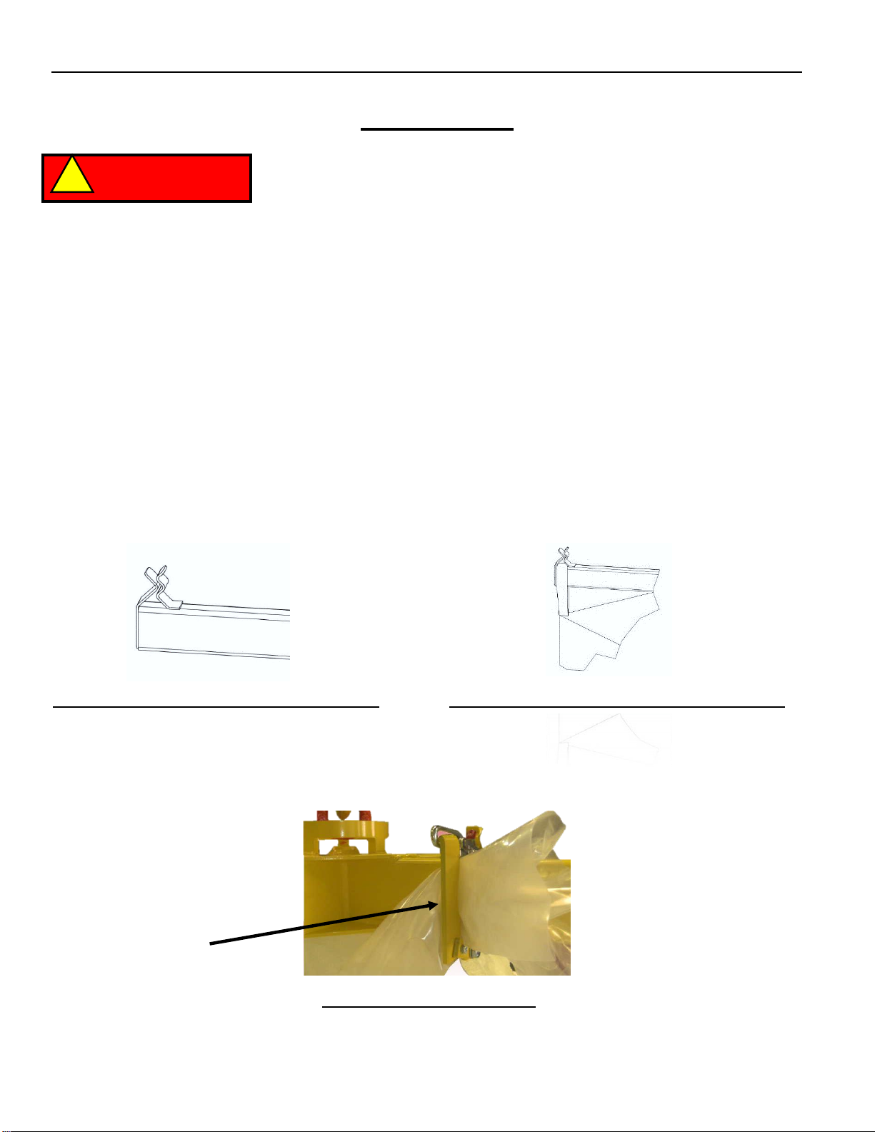
Connecting Bag to Z-CLIP™Bag Loop Retainers
The Z-CLIP™ Bag Loop retainer is shown in Figure 7. Slide bag strap through all (4) Z-CLIP™ bag
loop retainers until the bag strap is sitting correct as per Figure 8.
Connection of bulk bag Liner
If the bulk bag being used is supplied with a liner then the bulk bag liner should be connected to the
liner clamp supplied. Figure 9 shows the bulk bag Liner attached to the liner clamp.
Liner Clamp
Figure 9: Bag Liner Clamp
Figure 7: Z-CLIP™ Bag Loop Retainer
DANGER
!
Figure 8: Bag Loop Location in Z-CLIP™
It is the responsibility of the owner/user to install, inspect, test,
maintain, and operate all lifting equipment in accordance with
local, national, and international regulations. All personnel that
interact with lifting equipment must read and understand any
and all operating instructions or manuals that pertain to this
equipment. If the owner/user requires additional information, or
if any information provided in the manuals is unclear, contact the
manufacturer for clarification or further instructions. Do not
install, inspect, test, maintain, or operate any lifting equipment
unless the information is fully understood.
A regular schedule of inspection of lifting equipment should be
established and records maintained in accordance with any and
all applicable regulatory requirements.

FLEXICON®BULK-OUT®Bulk Bag Discharger Installation and Operation Manual - 17 -
FLEXICON CORPORATION 2400 Emrick Boulevard ■ Bethlehem, PA 18020-8006 USA
Tel: 1-888-FLEXICON ■ Tel: 1-610-814-2400 ■ Fax: 1-610-814-0600 ■ www.flexicon.com
Copyright 2003 FLEXICON®
Loading a bulk bag onto a BFF Frame
•Remove the bulk bag lift frame from the receiving cups using a forklift truck. Note that the
length of the forks on the forklift truck must be a minimum of 61 ½” long.
•Position the bulk bag lift frame a short distance over the top of the bulk bag.
•Pass the loops of the bulk bag over and onto the self-retaining Z-CLIP™bag loop retainers.
•Raise the bulk bag lift frame and bulk bag with a forklift truck and position over the receiving
cups on top of each Extension Arm.
•Lower the bulk bag lift frame into the cradles, which self-centers the bulk bag in the BULK-
OUT®Bulk Bag Discharger.
•The bulk bag should sit 1” to 2” above the safety frame.
Loading a bulk bag onto a BFC Frame
•With the hoist and trolley positioned all the way out on the overhung end of the beam, lower
the Bag Lift Frame via the hoist. Always position the bulk bag so that the center of the bag is
as close to the centerline of the Bag Lift Frame as possible. See Figure 10. The acceptable
window of operation is no more than 6 inches of misalignment between the center lines of the
bag and the frame when beginning the lift.
•Position the bag lift frame a short distance over the top to the bulk bag and Pass the loops of
the bulk bag over and into the self-retaining Z-CLIP™ bag loop retainers. Note the orientation
of the Bag Lift Frame which should be positioned square to the Discharger. See Figure 11.
•Raise the bulk bag and lift frame with the hoist only to a height of 2 inches off the ground and
stop lifting. Ensure the bulk bag is not swaying in any direction before proceeding.
•Raise the bulk bag and bag lift frame and bulk bag via the hoist then traverse the hoist and
trolley to the center of the frame.
•Lower the bag lifting frame and bulk bag via the hoist until the bulk bag sits 1” to 2” above the
safety frame.
Lift and traverse the bulk bag in a smooth continuous
fashion. Starting and stopping can cause undesirable
swaying of the bag. See Figure 12.
At no time should an operator stand under the bulk
bag when it is being lifted into or out of the frame.
CAUTION
!
DANGER
!
WARNING
!
Do not rest a Bulk Bag on the safety frame cross brace.
Doing so can interfere with proper operation of the
equipment and potentially create an unsafe condition.

FLEXICON®BULK-OUT®Bulk Bag Discharger Installation and Operation Manual - 18 -
FLEXICON CORPORATION 2400 Emrick Boulevard ■ Bethlehem, PA 18020-8006 USA
Tel: 1-888-FLEXICON ■ Tel: 1-610-814-2400 ■ Fax: 1-610-814-0600 ■ www.flexicon.com
Copyright 2003 FLEXICON®
Figure 12: Swaying Bulk Bag
Figure 11: Bag Lift Frame Orientation
Figure 10: Bag Lift Position
Top View
Front View
Front View
FLEXICON®BULK-OUT®Bulk Bag Discharger Installation and Operation Manual - 19 -
FLEXICON CORPORATION 2400 Emrick Boulevard ■ Bethlehem, PA 18020-8006 USA
Tel: 1-888-FLEXICON ■ Tel: 1-610-814-2400 ■ Fax: 1-610-814-0600 ■ www.flexicon.com
Copyright 2003 FLEXICON®
OPTIONAL EQUIPMENT
Available options for the FLEXICON® BULK-OUT®Bulk Bag Discharger:
•FLOW-FLEXER®Bulk Bag Agitation Device
•POP-TOP®Bulk Bag Elongation Option (BFF only)
•POWER-CINCHER®Flow Control Valve
•TELE-TUBE®Telescoping Tube (Single and double wall)
•Iris Valve and CVD Interface
•Load Cells
•Hoist and Trolley Option (BFC only)
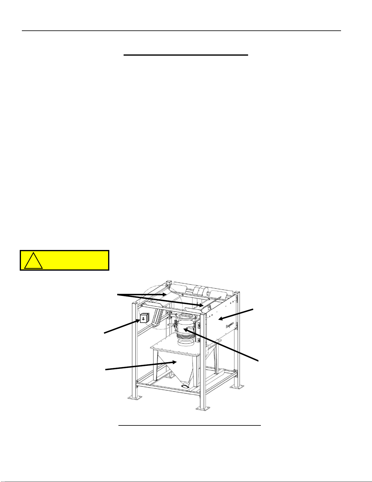
FLOW-FLEXER®Bulk Bag Agitation Device (Option)
Two pneumatically driven ‘paddles’ raise and lower the bottom edges of a bulk bag to direct material
into the bag outlet spout. The bag is also raised into a steep ‘V’ shape to promote total evacuation of
material.
FLOW-FLEXER®Operation
To operate the FLOW-FLEXER®, turn the selector switch to ‘ON’ and ‘Off’ as required. Where
applicable the operation may also be controlled automatically from a remote PLC or control panel.
The timer is factory set at 3 seconds “On” with 7 second “Intervals”.
The operator who is in control of the FLOW-FLEXER®should be
aware at all times of other personnel in the immediate area.
Figure 13 : FLOW-FLEXER®Arrangement
Side Safety
Shields
FLOW
FLEXER®
Control
Panel
(Optional)
Hopper
(2) FLOW
FLEXER®
Paddles
(Optional)
Teletube
CAUTION
!
This manual suits for next models
2
Table of contents
Other Flexicon Industrial Equipment manuals

Popular Industrial Equipment manuals by other brands

ABB
ABB HT567639 Operation manual

WEISS
WEISS NR Series Mounting instructions

Mayr
Mayr EAS 437 Series Installation and operation instructions

stellar labs
stellar labs TireMan 4110 owner's manual

Siemens
Siemens SINUMERIK ONE NCU 1760 Equipment manual

Hypertherm
Hypertherm EDGE Ti Lifter Repair Field Service Bulletin

Yamaha
Yamaha SIGMA-G5SII Service information

Thermal Edge
Thermal Edge A2W30120 User's & technical manual

Doosan
Doosan 7/124 Operation & maintenance manual

TriangleTube
TriangleTube PRESTIGE Excellence Series manual

Graco
Graco Therm-O-Flow 20 Instructions - parts

HEIDENHAIN
HEIDENHAIN M12 Mounting instructions


