Flexicon BFF User manual

FLEXICON CORPORATION 2400 Emrick Boulevard Bethlehem, PA 18020-8006 USA
Tel: 1-888-FLEXICON Tel: 1-610-814-2400 Fax: 1-610-814-0600 www.flexicon.com
FLEXICON
®
Bag Discharge Frame
Models: BFF & BFC
Installation and Operation Manual
Revised November, 2003

FLEXICON®
Bulk Bag Discharge Frame Installation and Operation Manual - 2 -
FLEXICON CORPORATION 2400 Emrick Boulevard Bethlehem, PA 18020-8006 USA
Tel: 1-888-FLEXICON Tel: 1-610-814-2400 Fax: 1-610-814-0600 www.flexicon.com
FOREWORD
Thank you and congratulations on your purchase of one of the safest, most reliable, bulk bag
discharging systems available. We are confident that you will find your FLEXICON
®
bulk bag
discharging system to be rugged, reliable and, most of all, simple to use. FLEXICON'S innovative,
common sense approach to unloading even the most difficult materials from bulk bags makes
installation and operations of your FLEXICON
®
bulk bag discharging system quick and simple.
Please refer to the following instructions for installing and operating your FLEXICON
®
bulk bag
discharging system. If you encounter any problems, which prevent safe, reliable installation and/or
operation of the system, please call the FLEXICON
®
service department immediately, we will be
happy to address any concerns you may have.
The bulk bag frame appearance may be slightly different than the frame details depicted in this
manual. Any differences do not affect the function, capacity or operation of the equipment.

FLEXICON®
Bulk Bag Discharge Frame Installation and Operation Manual - 3 -
FLEXICON CORPORATION 2400 Emrick Boulevard Bethlehem, PA 18020-8006 USA
Tel: 1-888-FLEXICON Tel: 1-610-814-2400 Fax: 1-610-814-0600 www.flexicon.com
TABLE OF CONTENTS
1. Introduction
2. Precautions
3. Bulk bag discharge frame installation procedure
4. BFC- upper frame installation
5. Loading a bulk bag on the frame
6. Interfacing the bulk bag downspout with the special cover and iris valve
7. Flow Flexer
®
Bulk Bag Agitation Device- Purpose
8. Flow Flexer
®
Bulk Bag Agitation Device- Installation
9. Control & adjustment of Flow Flexers
®
Bulk Bag Agitation Device
10. Spare Parts

FLEXICON®
Bulk Bag Discharge Frame Installation and Operation Manual - 4 -
FLEXICON CORPORATION 2400 Emrick Boulevard Bethlehem, PA 18020-8006 USA
Tel: 1-888-FLEXICON Tel: 1-610-814-2400 Fax: 1-610-814-0600 www.flexicon.com
INSTALLATION OF THE TYPICAL
FLEXICON
®
BULK BAG DISCHARGE FRAME
*Please read this manual prior to installing your system.
1. INTRODUCTION
Locating and installing the bulk bag discharge frame is a very important step in the proper
and efficient use of this equipment. We recommend that you follow these procedures to
achieve complete satisfaction.
2. PRECAUTIONS
Please refer to the operation manual for the hoist and trolley for proper procedures
when using this device. For safety reasons, it is important to establish proper
connection to the bulk bag lifting frame and to operate the hoist and trolley in the
proper manner.
Do not rest a Bulk Bag on the safety frame cross brace. Doing so can interfere with
proper operation of the equipment and potentially create an unsafe condition.
Do not use the bulk bag discharge frame for materials other than what it was specified for.
If you add new materials please consult with FLEXICON CORPORATION before doing so.
Do not allow agglomerating or hygroscopic material to remain in the FLEXICON
®
bulk bag
discharge frame for extended periods of time. These materials may tend to set up or
become hard making it difficult to discharge the bulk bag.
Make sure the vent tube on the cover, if supplied, is fitted with a filter sock before
discharging a bulk bag.
Do not allow tools, rags, bags (other than bulk bags called for in the specifications) to
remain in or enter the system during its operation. Periodically check that all bolted
connections are tight, as they might become loose in transit or during operation.
Do not mount peripheral equipment on the bulk bag frame.
Do not allow individuals to stand on any part of the frame as bulk bags are being loaded
onto or unloaded from it.
3. BULK BAG DISCHARGE FRAME INSTALLATION PROCEDURE
3.1 Before beginning the actual installation of your bag discharge frame, check the appropriate
list below to ensure that all of the components necessary for the BFF or BFC model you
ordered are present, less options.

FLEXICON®
Bulk Bag Discharge Frame Installation and Operation Manual - 5 -
FLEXICON CORPORATION 2400 Emrick Boulevard Bethlehem, PA 18020-8006 USA
Tel: 1-888-FLEXICON Tel: 1-610-814-2400 Fax: 1-610-814-0600 www.flexicon.com
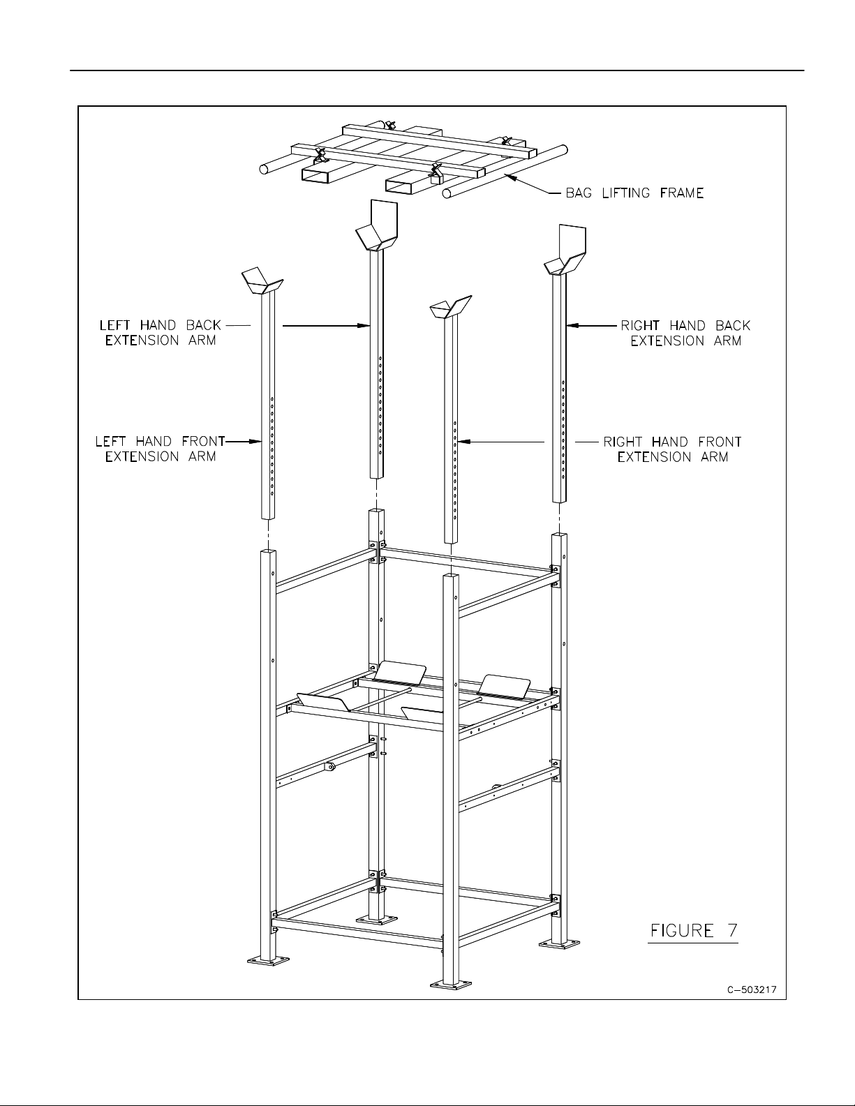
3.1.1 BFF with static or Pop-Top™ Extension Arms (Reference figure 7)
(1) Base frame
(2) Front extension arms
(2) Rear extension arms
(1) Bag lift frame
The
frame will be shipped with the extension arms installed and in the lowest height
position and may need to be adjusted for your bag requirements. See step 3.18 for final
adjustment.
3.1.2 BFC (Reference figure 10)
(1) Base frame
(2) Front extension arms
(1) Left hand rear extension arm
(1) Right hand rear extension arm
(3) Cross brace "D" (diagonals)
(1) Back cross brace "F"
(1) Front cross brace "F"
(1) S7 beam
(2) Cross brace “G”
* (2) Cross brace “H”
* (2) Cross brace "I"
(1) Bag lift frame
(1) Hardware kit
*Not on all models
3.1.3 If your base frame has been supplied as a kit, assemble the base frame following steps 3.2
thru 3.13. Otherwise begin installation at step 3.14.
3.2 Base frame assembly procedure
Throughout this entire procedure, whenever a connection is made with a ½-13 stud or
bolt and hex nut, thread nut on to the point where it engages the split lock washer then,
using a wrench, tighten the nut ½ turn! This is an initial tightening spec which will allow
for the necessary adjustment in leveling and squaring of the frame while firmly securing the
components together.
It is suggested that you familiarize yourself with this procedure and all of the associated
components before beginning assembly.
3.3 Begin assembly by orienting the left and right back legs, as shown in figure 1, on a flat and
level work surface.
3.4 Assemble three of cross brace “A” to the appropriate pairs of studs using (1) ½" flat
washer, (1) ½" split lock washer and (1) ½-13 hex nut per stud. (see figure 2)

FLEXICON®
Bulk Bag Discharge Frame Installation and Operation Manual - 6 -
FLEXICON CORPORATION 2400 Emrick Boulevard Bethlehem, PA 18020-8006 USA
Tel: 1-888-FLEXICON Tel: 1-610-814-2400 Fax: 1-610-814-0600 www.flexicon.com
3.5 With the rear side assembly still lying flat on the work surface, assemble (2) of cross brace
"A", (1) of cross brace "B" and (1) of cross brace "C" to each rear leg. Take particular
notice to the position and orientation of each cross brace in the assembly. As shown in
figure 3, the orientation of cross brace "C" on the left back leg is such that the (2) tapped
holes on the inside of the brace are oriented toward the high end and facing inward. The
other brace "C” on the right back leg has the (2) tapped holes oriented toward the low end
and also facing inward. The cross brace "B" on the left back leg is oriented with the single
pair of tapped holes nearest one end of the base, toward the high end and facing cross
brace "C". This orients the (4) thru and (4) tapped holes toward the outside of the frame.
The cross brace "B" on the right back leg is oriented with the single pair of tapped holes
toward the lower end and facing it's associated cross brace "C".
3.6 With the assembly still lying flat on work surface, assemble the left and right front legs to
the loose ends of the cross braces “A”, "B" & “C”. Take particular notice to the difference
between the left and right front legs. The left front leg when properly oriented on the frame
will have a single pair of studs facing toward the right side of the frame with all of the other
studs facing downward (see figure 3). The right leg is the exact opposite of the left.
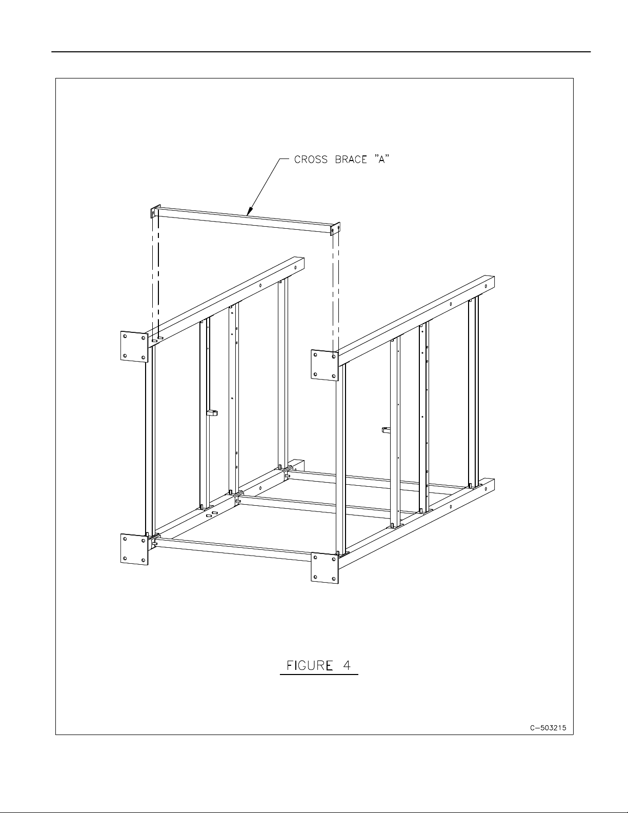
3.7 With assembly still lying flat on the work surface, assemble the remaining cross brace "A"
to the opposing pair of studs located on the inside of each front leg (see figure 4). It may
be necessary to spread the front legs apart slightly to facilitate the insertion of this brace.
3.8 With the preliminary assembly completed, stand the frame upright. It is essential that the
leveling and squaring sequence be done as accurately as possible to ensure trouble free
installation of the remaining components and options.
Because the leveling and squaring process is imperative, we highly recommend that this
be done only after the frame has been placed in it's final location. If relocation of the frame
is necessary at any time, the leveling and squaring process must be repeated.
3.9 The frame is now ready for final alignment via leveling and squaring the various
components. All of the hardware should have been tightened as specified in step 3.2.
This will allow the various components of the frame to be nudged (method by choice
of customer) into alignment.
There is no particular sequence to the aligning process. As each component is
aligned/leveled, tighten each connection to 40 ft/lbs of torque with no exception. When
completed the frame should look like figure 5, less the safety frame cross braces.
3.10 The frame is now prepared for the installation of the safety frame cross braces.
3.10.1 If you have purchased your frame with the Flow Flexer
®
Bulk Bag Agitation Device option,
there is additional assembly required. Stop here and proceed to section 8, “Flow Flexer
®
Bulk Bag Agitation Device assembly procedure", for incorporation of all associated
components, otherwise proceed to step 3.11.

FLEXICON®
Bulk Bag Discharge Frame Installation and Operation Manual - 7 -
FLEXICON CORPORATION 2400 Emrick Boulevard Bethlehem, PA 18020-8006 USA
Tel: 1-888-FLEXICON Tel: 1-610-814-2400 Fax: 1-610-814-0600 www.flexicon.com
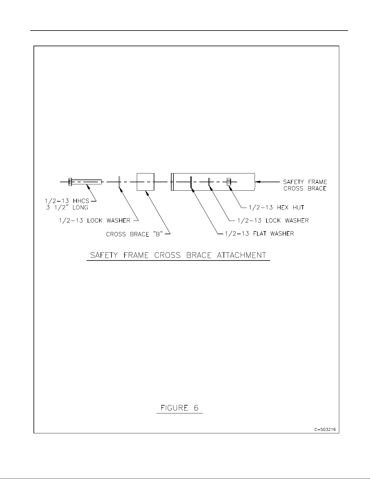
3.11 Install one safety frame cross brace between the (2) "B” cross braces by first orienting the
cross braces so that the (2) ¾” I.D. bushings, supplied in each safety frame cross brace,
are facing inward (see figure 5). Bolt in place with (4) ½-13 x 3½“ long bolts, (8) ½" flat
washers, (4) split lock washers and (4) ½- 13 hex nuts (see figure 6). Do not tighten the
hardware.
3.12 Before installing the remaining safety frame cross brace, the (2) "E" cross braces must be
inserted into the ¾" I.D. bushings in the opposing faces of the two safety frame cross
braces. Complete the assembly by bolting the remaining safety frame in place with
identical hardware as specified in step 3.11. Torque all hardware to 40 ft/lbs.
3.13 This completes the assembly of the base frame.
3.14 Anchor the base frame to the foundation using the appropriate grade 5 (or better)
hardware, type to be determined by customer. (16) bolts/anchors are required.
3.15 If you have purchased a BFC frame proceed to section 4 for “BFC upper frame
assembly procedure", otherwise continue with step 3.16.
3.16 If your base frame was factory assembled, the static or "pop-top” extension arms will have
been factory installed and may only need final adjustment described in step 3.18,
otherwise proceed with step 3.17.
3.17 Install the (4) extension arms to the base frame. Orient each arm as shown in figure 7.
Slide into the top of each respective leg to the lowest height setting and secure with (4) ¾"
diameter x 3 ½” long clevis pins/safety clips.
3.18 It may be necessary to adjust the height of the extension arms to accommodate the size of
the bag you are using in your application. The height is set properly when the bottom of
the full bulk bag is 1 to 2 inches above the center of the safety frame, with or
without Flow Flexers™. It may be necessary to position the bag above or below the
preferred 1 to 2 inch distance based on your hopper/bag downspout configuration. The
holes in the legs provide a range of adjustment in 2" increments.
4. BFC UPPER FRAME ASSEMBLY PROCEDURE
4.1 Throughout this entire procedure, whenever a connection is made with either ½ -13 or
¾-10 hardware, do not tighten to final torque spec. Unless otherwise specified, thread nut
on to the point where it engages the split lock washer then, using a wrench, tighten the nut
½ turn! This allows for final alignment before tightening to final torque.
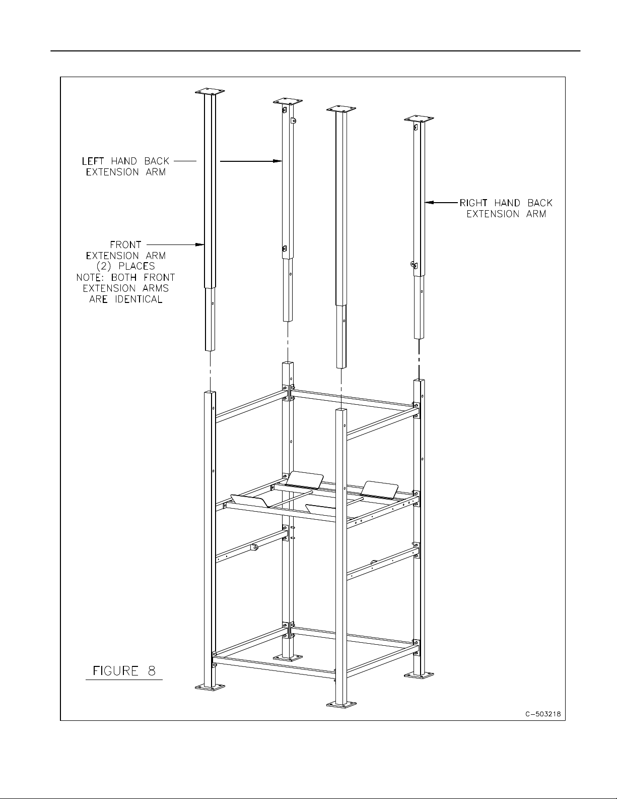
4.2 Begin by installing the (4) extension arms (see figure 8). There are (2) identical front
extension arms, (1) left hand back extension and (1) right hand back extension arm. The
front extension arms are longer than the rear arms and have only two tabs at the top. The
right hand back arm has two tabs 90 degrees opposed to each other at the bottom of the
arm. The left hand back arm has three tabs, one located at the bottom and the other two
located at the top 90 degrees opposed to each other.

FLEXICON®
Bulk Bag Discharge Frame Installation and Operation Manual - 8 -
FLEXICON CORPORATION 2400 Emrick Boulevard Bethlehem, PA 18020-8006 USA
Tel: 1-888-FLEXICON Tel: 1-610-814-2400 Fax: 1-610-814-0600 www.flexicon.com
4.3 Assemble the arms in their respective legs. Be sure to orient them as shown in figure 8.
Secure them in place with (1) ¾-10 x 4 ½” long bolt, (2) ¾" flat washers, (1) ¾" split lock
washer and (1) ¾-10 hex nut per leg. Torque the hardware to 105 ft/lbs.
4.4 Assemble the back cross brace "F" to the top of the rear extension arms (see figure 9).
Attach using (8) ¾-10 x 2" long bolts, (16) ¾" flat washers, (8) ¾-10 split lock washers and
(8) ¾-10 hex nuts.
4.5 Assemble the front cross brace "F” to the top of the front extension arms (see figure 9).
Assemble using (8) ¾-10 x 2" long bolts, (16) ¾" flat washers, (8) ¾" split lock washers and
(8) ¾-10 hex nuts.
4.6 Install both cross braces, "I", to the frame tabs provided using (4) ½-13 x 1 ½” long bolts, (8)
flat washers, (4) split lock washers, and (4) ½-13 hex nuts (see figure 9).
4.7 Assemble the hoist beam to the front and rear “F" cross braces (see figure 9).
Assemble using (8) ¾-10 x 2 ½" long bolts, (16) ¾” flat washers (8) ¾” split lock washers
and (8) ¾-10 hex nuts.
4.8 Assemble the (3) “D" cross braces (see figure 9). The orientation of the braces will be self
evident. Attach using (6) ½-13 x 1 ½” long bolts, (12) ½” flat washers, (6) ½" split lock
washer and (6) ½-13 hex nuts.
4.9 Assemble the (2) “G" cross braces which connect between the inside, rear bolt on each side
of the front cross brace "F" to front extension arm assembly to the holes provided on top of
the hoist beam at the back (see figure 10). There is (1) left and (1) right hand "G" brace.
There is an angle cut on one end of each brace and it will be self evident as to the proper
orientation.
4.10 Install the two “H” braces to the top of the frame assembly in the same manner as the “G”
braces are installed (see figure 10).
4.11 Square the various components of the BFC upper section and tighten all hardware to the
following final torque specification:
½-13 UNC to 40 ft/lbs.
¾-10 UNC to 105 ft/lbs.
4.12 Assemble the hoist to the hoist beam as per the manufacturers instructions supplied with
the hoist.
4.13 Assemble the hoist tag line between the two 2" x 2" x ¼" angles of which (1) is located on
each end of the beam. Assemble the ¼-20 x 1 ½" long eye bolt to one of the angles via the
hole at the end of the angle and secure in place with (2) ¼" flat washers, (1) ¼" split lock
washer and a ¼-20 hex nut. On the remaining angle, assemble the ¼-20 x 5" long eyebolt
with identical hardware as the other eyebolt except leaving the hardware loose for
adjustment purposes. Loop one end of the tag line thru one of the eyebolts and secure with

FLEXICON®
Bulk Bag Discharge Frame Installation and Operation Manual - 9 -
FLEXICON CORPORATION 2400 Emrick Boulevard Bethlehem, PA 18020-8006 USA
Tel: 1-888-FLEXICON Tel: 1-610-814-2400 Fax: 1-610-814-0600 www.flexicon.com
a cable clamp. Thread the loose end of the tag line thru the (4) cable trolley's then thru the
remaining eyebolt and secure with a cable clamp. Adjust the 5" eyebolt to the desired
tension and secure hardware in place. Trim any excess cable to within 2" of each cable
clamp.
5. LOADING A BULK BAG IN THE FRAME
Please refer to the operation manual for the hoist and trolley for proper procedures
when using this device. For safety reasons, it is important to establish proper
connection to the bulk bag lifting frame and to operate the hoist and trolley in the
proper manner.
Do not rest a Bulk Bag on the safety frame cross brace (See Fig 5). Doing so can
interfere with proper operation of the equipment and potentially create an unsafe
condition.
5.1 BFF Procedure
5.1.1 Remove the bag lift frame from the receiving cups using a forklift truck.
5.1.2 Position the bag lift frame a short distance over the top of the bulk bag.
5.1.3 Pass the loops of the bulk bag over and onto the self-retaining bag loop retainers.
5.1.4 Raise the bag lift frame and bulk bag with a forklift truck and position over the receiving
cups on top of each extension arm.
5.1.5 Lower the bag lift frame into the cradles, which self centers the bag in the bulk bag
discharge frame. The height is set properly when the bottom of the full bulk bag is 1 to 2
inches above the center of the safety frame, with or without Flow Flexers
®
. It may be
necessary to position the bag above or below the preferred 1 to 2 inch distance based on
your hopper/bag downspout configuration. Do not rest bulk bag on the safety frame cross
brace.
5.2 BFC Procedure
5.2.1 With the hoist and trolley positioned all the way out on the overhung end of the beam,
lower the bag lift frame via the hoist. Always position the bulk bag so that the center of the
bag is as close to the centerline of the bag-lifting frame as possible. The acceptable
window of operation is NO MORE THAN 12” of misalignment between the centerlines of
the bag and the frame when beginning the lift.
5.2.2 Position the bag lift frame a short distance over the top to the bulk bag.
5.2.3 Pass the loops of the bulk bag over and onto the self-retaining back loop retainers.

FLEXICON®
Bulk Bag Discharge Frame Installation and Operation Manual - 10 -
FLEXICON CORPORATION 2400 Emrick Boulevard Bethlehem, PA 18020-8006 USA
Tel: 1-888-FLEXICON Tel: 1-610-814-2400 Fax: 1-610-814-0600 www.flexicon.com
5.2.4 Raise the bag lift frame and bulk bag via the hoist then position the hoist and trolley in the
center of the frame. Take care to lift the bag and frame smoothly, without “jerking” the bag
into the air.
5.2.5 The height is set properly when the bottom of the full bulk bag is 1 to 2 inches above the
center of the safety frame, with or without Flow Flexers
®
. It may be necessary to position
the bag above or below the preferred 1 to 2 inch distance based on your hopper/bag
downspout configuration. Do not rest bulk bag on the safety frame cross brace.
6. INTERFACING THE BULK BAG DOWNSPOUT WITH
THE SPECIAL COVER AND IRIS VALVE
Many bulk bag frames feature an iris valve to cinch and release the bulk bag downspout
controlling the flow of material from the bag. A number of additional options are also
available in the area of the bulk bag downspout. These options are not depicted in this
manual. Please refer to the installation and operation manual furnished with the specific
equipment being installed.
The typical outlet spout of a bulk bag has a protective cover, which is released by
loosening a drawstring. The outlet spout is then pulled downward through the open iris
valve.
The open, hinged door on the special cover provides access to pull the outlet spout taut,
while using the iris valve handle to cinch the spout closed. When this is done the operator
can close the door and release the draw string of the bag spout with no danger of an
uncontrolled burst of material from the bag.
By opening the iris valve slowly the operator can control the flow of material gradually and
incrementally. Opening the valve slowly also eliminates dusting caused by uncontrolled
material surges displacing air from the hopper too rapidly.
During normal operation the door should remain closed, when the iris valve is opened to
permit flow of material out of the bag.
7. FLOW FLEXER
®
BULK BAG AGITATION DEVICE
Semi or non free flowing materials are handled by using Flow Flexer
®
Bulk Bag Agitation
Device plates to manipulate the bulk bag.
Flow Flexer
®
Bulk Bag Agitation Device plates perform two critical functions:
1 . They dislodge bulk materials that have compacted during shipment and
storage.
2. They raise the bottom of the bag into a steep "V" shape insuring complete
discharge.

FLEXICON®
Bulk Bag Discharge Frame Installation and Operation Manual - 11 -
FLEXICON CORPORATION 2400 Emrick Boulevard Bethlehem, PA 18020-8006 USA
Tel: 1-888-FLEXICON Tel: 1-610-814-2400 Fax: 1-610-814-0600 www.flexicon.com
As the bag continues to empty the increased stroke of the cylinders raises the bottom of the
bag increasingly higher eliminating dead spots.
When empty, the bottom of the bag remains in a steep "V" shape completely discharging
even stubborn material with no manual intervention.
After the bag is empty the operator turns off the Flow Flexer
®
Bulk Bag Agitation Device and
opens the access door to shake out any material caught in the creases of the spout.
8. FLOW FLEXER
®
BULK BAG AGITATION DEVICE ASSEMBLY PROCEDURE
8.1 The following instructions will cover the installation of the Flow Flexer
®
Bulk Bag Agitation
Device option to the base frame.
8.1.1 If you are adding this option to an unassembled base frame, proceed to step 8.3, otherwise
continue with step 8.2.
8.2 Using figure 5 as a reference, unbolt one of the safety frame cross braces and remove the
(2) “E" cross braces. Proceed to step 8.4.
8.3 Using figure 5 as a reference, assemble the rear safety frame cross brace with the bushings
oriented as shown. Using (4) ½-13 x 3½“ long bolts, (8) ½" flat washers, (4) ½” split lock
washers and (4) ½-13 hex nuts.
8.4 Using figure 11 as a reference, slide a ¾" split collar onto each end of the rod on each side
of the Flow Flexer
®
Bulk Bag Agitation Device plates, (4) total.
8.5 Assemble the remaining safety frame cross brace to the appropriate side of the (2) Flow
Flexer
®
Bulk Bag Agitation Device plates by carefully aligning then sliding the rod ends of
the Flow Flexer
®
plates into the ¾“ I.D. bushings on the inside face of the safety frame
cross brace (see figure 11).
8.6 Position the loose Flow Flexer
®
Bulk Bag Agitation Device plates/safety frame cross brace
into the frame, aligning then carefully inserting the opposite end of the rods on the Flow
Flexer
®
Bulk Bag Agitation Device plates into the ¾" I.D. bushings of the other safety frame
cross brace. Secure safety frame cross brace to frame using (4) ½-13 x 3½" long bolts, (8)
½" flat washers, (4) ½" split lock washers and (4) ½-13 hex nuts. Before torquing hardware,
make sure that the Flow Flexer
®
Bulk Bag Agitation Device plates rotate smoothly. Torque
hardware to 40 ft/lbs.
8.7 Center the Flow Flexer
®
Bulk Bag Agitation Device plates between the safety frames, slide
each of the (4) split collars outward toward the bushings then lock them in place via the
locking screw. Check again to make sure that the Flow Flexer
®
Bulk Bag Agitation Device
plates rotate freely with minimal side play (see figure 11).

FLEXICON®
Bulk Bag Discharge Frame Installation and Operation Manual - 12 -
FLEXICON CORPORATION 2400 Emrick Boulevard Bethlehem, PA 18020-8006 USA
Tel: 1-888-FLEXICON Tel: 1-610-814-2400 Fax: 1-610-814-0600 www.flexicon.com
8.8 Mount each air cylinder between the tab on the bottom of the Flow Flexer
®
Bulk Bag
Agitation Device plate to the tab on the inside of cross brace "C" using the (4) clevis and
cotter pins (see figure 11). Make sure that the tubing fittings on both air cylinders are
oriented toward the front of the frame as shown.
8.9 Assemble (4) "P" clips to the bottom of each safety frame cross brace using (8) ¼“dia x ¾"
long drive rivet anchors and (8) ¼" flat washers. The ¼" steel flat washer is placed onto
and against the head of the rivet anchor which is then placed thru the holes in the “P" clip.
The portion of the rivet anchor protruding thru the "P" clip is then placed into the hole in the
safety frame. While firmly pressing the components against the frame, drive the steel core
pin of the rivet anchor into the rivet until the head of the pin is flush to the head of the rivet
(see figure 12).
8.10 Mount the Flow Flexer
®
Bulk Bag Agitation Device control panel to the frame. The panel is
bolted to the frame in four locations with (4) 5/16-18 x 1" long hex head bolts, (4) 5/16 split
lock washers and (4) 5/16 flat washers at two places on the bottom of cross brace "B" and
two on the inside face of cross brace "C" (see figure 13). The method of installing the panel
using drive rivet anchors and ¼" flat washers is identical to that described in step 8.9.
8.11 Assemble (2) "P" clips, (1) in the center of the underside of each cross brace "B" using rivet
anchors as described in step 8.9.
8.12 Connect four lengths (cut to length by customer) of the 3/8" O.D. ¼" I.D. plastic tubing
between the male run tees on the solenoid manifold to the fittings on the air cylinders. Run
the tubing to the right air cylinder thru the (6) “P" clips, (2) on underside of the rear safety
frame cross brace, as shown in figures 12, 13 and 14.
8.13 Installation of the Flow Flexer
®
Bulk Bag Agitation Device Plexiglas Shields.
8.14 To ensure the delivery of a quality product, FLEXICON®ships the (2) Plexiglas shields
loose to decrease the possibility of damage during shipment. This includes leaving the
protective peel-off covering on the shields which must be removed before installation to the
frame.
8.15 The shields span the area between both pairs of cross braces "B" and "C" on the outside
of the frame. In figure 5, the (8) small holes, (4) on cross brace "B” and (4) on cross brace
"C” are visible on the right side of the frame.
8.16 Position the shield to clear the four existing bolts and washers securing the safety frames
Via the (4) large holes in the shield while aligning the remaining holes in cross braces "B"
and "C". Secure with (8) ¼" rivet anchors, (8) ¼" flat washers per shield. DO NOT USE
EXCESSIVE FORCE to install rivet anchors as this may cause damage to the shield.

FLEXICON®
Bulk Bag Discharge Frame Installation and Operation Manual - 13 -
FLEXICON CORPORATION 2400 Emrick Boulevard Bethlehem, PA 18020-8006 USA
Tel: 1-888-FLEXICON Tel: 1-610-814-2400 Fax: 1-610-814-0600 www.flexicon.com
9. CONTROL AND ADJUSTMENT OF THE FLOW FLEXERS
®
Bulk Bag Agitation Device
The control panel for the Flow Flexers
®
Bulk Bag Agitation Device is mounted on one of the
front corner posts of the bulk bag frame.
The on/off control is located on the front of the control panel.
Inside the panel are two timers. They are marked on and off. These are used to set the on
time and dwell time of the Flow Flexer
®
Bulk Bag Agitation Device. Typical settings of the
timers are 30 to 40 seconds, but they can be adjusted to whatever suits the material in the
bag.
The air cylinders to move the Flow Flexer
®
Bulk Bag Agitation Device plates are located in
the center of and directly beneath the plates.
There are adjustments for the pressure in both directions (up and down) at the air inlet into
the cylinder.
There are also cushioning adjustments at the top and bottom of the air cylinder to prevent
“hard stopping" at the end of a stroke. These adjustments are done with an Allen wrench.
The air regulator for the Flow Flexer
®
Bulk Bag Agitation Device is mounted on the frame
near the control panel.
Typically a maximum of 80-psi air is supplied to the regulator and it is adjusted to suite the
particular application. Different pressures can be used as conditions warrant.
The air regulator system contains a lubrication reservoir with a screw cap inlet port on top.
A standard unit typically requires two to four drops of oil per hour of usage. The
recommended oil for refill is ten weight air-lubricating oil.

FLEXICON®
Bulk Bag Discharge Frame Installation and Operation Manual - 14 -
FLEXICON CORPORATION 2400 Emrick Boulevard Bethlehem, PA 18020-8006 USA
Tel: 1-888-FLEXICON Tel: 1-610-814-2400 Fax: 1-610-814-0600 www.flexicon.com

FLEXICON®
Bulk Bag Discharge Frame Installation and Operation Manual - 15 -
FLEXICON CORPORATION 2400 Emrick Boulevard Bethlehem, PA 18020-8006 USA
Tel: 1-888-FLEXICON Tel: 1-610-814-2400 Fax: 1-610-814-0600 www.flexicon.com
FLEXICON®
Bulk Bag Discharge Frame Installation and Operation Manual - 16 -
FLEXICON CORPORATION 2400 Emrick Boulevard Bethlehem, PA 18020-8006 USA
Tel: 1-888-FLEXICON Tel: 1-610-814-2400 Fax: 1-610-814-0600 www.flexicon.com

FLEXICON®
Bulk Bag Discharge Frame Installation and Operation Manual - 17 -
FLEXICON CORPORATION 2400 Emrick Boulevard Bethlehem, PA 18020-8006 USA
Tel: 1-888-FLEXICON Tel: 1-610-814-2400 Fax: 1-610-814-0600 www.flexicon.com
FLEXICON®
Bulk Bag Discharge Frame Installation and Operation Manual - 18 -
FLEXICON CORPORATION 2400 Emrick Boulevard Bethlehem, PA 18020-8006 USA
Tel: 1-888-FLEXICON Tel: 1-610-814-2400 Fax: 1-610-814-0600 www.flexicon.com
FLEXICON®
Bulk Bag Discharge Frame Installation and Operation Manual - 19 -
FLEXICON CORPORATION 2400 Emrick Boulevard Bethlehem, PA 18020-8006 USA
Tel: 1-888-FLEXICON Tel: 1-610-814-2400 Fax: 1-610-814-0600 www.flexicon.com
FLEXICON®
Bulk Bag Discharge Frame Installation and Operation Manual - 20 -
FLEXICON CORPORATION 2400 Emrick Boulevard Bethlehem, PA 18020-8006 USA
Tel: 1-888-FLEXICON Tel: 1-610-814-2400 Fax: 1-610-814-0600 www.flexicon.com
This manual suits for next models
1
Table of contents
Other Flexicon Industrial Equipment manuals


