Thermal Edge A2W30120 User manual

User & Technical Manual
Air to Water Heat Exchanger
Rev 1.0

1800 Hurd Drive ● Irving, Texas 75038 ● (972) 580-0200 ● (888) 580-0202 ● Fax (972) 580-0277
URL: www.thermal-edge.com ● Email: support@thermal-edge.com
SP-ENG-211-000-20 Rev 1.0 2 |P a g e
Title: Air to Water Heat Exchanger Technical Manual
Department: Product Management
Objective: To provide important information for maintenance, diagnostics and advance operations of the
Thermal Edge Air to Water Heat Exchangers.
Revision History:
Rev
Date
Owner
Description of Changes
1.0
10-03-22
L. Biru
Initial Release
Statement of Confidentiality
The Manual and other materials contain proprietary information, comprising Thermal Edge Inc.'s trade secrets.
Please maintain the confidentiality of all proprietary information during and after the term of the use agreement.
Also, please refrain from using this proprietary information in any other manner, including in any other
business, without Thermal Edge Inc.’s written approval.
Thermal Edge Inc. reserves the right to revise and otherwise modify the Manual to reflect changes in the
requirements, standards, and operating recommendations. The Manual is the sole property of Thermal Edge
Inc. It must be returned upon the expiration or the termination of the term of use agreement.
By accepting the Manual you have read and understand the Statement of Confidentiality and will abide by its
terms and conditions.

1800 Hurd Drive ● Irving, Texas 75038 ● (972) 580-0200 ● (888) 580-0202 ● Fax (972) 580-0277
URL: www.thermal-edge.com ● Email: support@thermal-edge.com
SP-ENG-211-000-20 Rev 1.0 3 |P a g e
TABLE OF CONTENTS
Overview ........................................................................................................................................................... 4
Unpacking and Inspecting the Heat Exchanger ....................................................................................................... 4
Moving the Heat Exchanger ................................................................................................................................. 5
Unit Label.......................................................................................................................................................... 5
Operation .......................................................................................................................................................... 5
Mounting the Heat Exchanger .............................................................................................................................. 6
Water Quality .................................................................................................................................................... 7
Unit Specifications .............................................................................................................................................. 8
Options ............................................................................................................................................................. 9
System Faults .................................................................................................................................................. 11
Digital Temperature Controller Programming ........................................................................................................ 11
Preventative Maintenance .................................................................................................................................. 15
Field Serviceable Parts ...................................................................................................................................... 16
Safety Information ........................................................................................................................................... 17
Troubleshooting Guide ...................................................................................................................................... 17
Physical Dimensions .......................................................................................................................................... 18
Warranty Information........................................................................................................................................ 20
Return Material Authorization (RMA) Procedure .................................................................................................... 21
Phoenix Contact Power Connection Instructions .................................................................................................... 22

1800 Hurd Drive ● Irving, Texas 75038 ● (972) 580-0200 ● (888) 580-0202 ● Fax (972) 580-0277
URL: www.thermal-edge.com ● Email: support@thermal-edge.com
SP-ENG-211-000-20 Rev 1.0 4 |P a g e
Overview
Thank you for your purchase of the Thermal Edge Air to Water Heat Exchanger. Our equipment is carefully
designed to cool and dehumidify the air in electronic component enclosures. Thermal Edge has designed air
to water heat exchangers for all types of electronic equipment enclosures providing capacity from 2,000 to
20,000 BTUH.
This manual will guide you through the installation, maintenance, diagnostics and advance operations of the
Air to Water Heat Exchanger. This manual contains important information for the end-user who installs,
maintains and/or operates the Air to Water Heat Exchanger.
Technical Support
By Phone: 972-580-0200 / 888-580-0202
(Monday –Friday, 7:30 am –5:00 pm Central Time)
By Email: support@thermal-edge.com
Our goal is to have continuous improvement for both our equipment and our documentation. We rely on and
appreciate your feedback to help us achieve our goal. Our technical support team is glad to work with you if
you require additional technical information not provided in this manual.
Unpacking and Inspecting the Heat Exchanger
Thermal Edge air conditioning equipment is designed, manufactured, and packed to prevent damage from
normal handling, shock and vibration during shipment. It is necessary to inspect your equipment upon receipt
to ensure that there is no visual or hidden damage.
All physical damage to packing or signs of damage to the equipment must be noted on the freight bill of lading.
Packages must be opened after receipt and inspected for any internal or concealed damage to the equipment
and to verify proper count and order fulfillment. Delivery without the pallet, other freight on top, damaged or
wet should be refused.
If the unit is to be transported after initial unpacking, place heat exchanger back in original packing to prevent
damage.
For shipment by UPS or freight carrier, repack as received and re-band to the pallet.

1800 Hurd Drive ● Irving, Texas 75038 ● (972) 580-0200 ● (888) 580-0202 ● Fax (972) 580-0277
URL: www.thermal-edge.com ● Email: support@thermal-edge.com
SP-ENG-211-000-20 Rev 1.0 5 |P a g e
Moving the Heat Exchanger
Heat exchangers are not designed to be shipped attached to an equipment enclosure. Heat exchangers
shipped which have internal damage due to shipping while attached to enclosures are warranty voided.
Unit Label
Each heat exchanger has a unit label. Be sure to record the data from the label to the template below and
keep this information in a safe place for warranty and ordering parts. To prevent damage to equipment,
electrical panel and wiring, and to prevent personal injury, assure that the power source is compatible with the
equipment before operating.
Operation
Thermal Edge heat exchangers, when sized correctly, will provide cooling to lower the air temperature inside
an enclosure to ensure its proper operating temperature. Thermal Edge heat exchangers operate as a “closed
loop” system with no exposure to, or introduction of, outside air. This ensures that the enclosure is separated
from, and is not contaminated with, ambient air, dirt, chemicals, dust, moisture or foreign matter so that
sensitive enclosure components are protected.
For units with the digital controller and solenoid valve option, the digital controller will monitor air temperature
inside the electrical enclosure via the temperature sensor and regulate function of the solenoid valve. The
valve controls the flow of water through the coil. As water flows through the coil it absorbs heat from air in the
electrical enclosure while also dehumidifying it. This process lowers the temperature of the air in the electrical
enclosure. The fan draws the hot air from the electrical enclosure and pulls it through the coil and back into
the electrical enclosure at a lower temperature.

1800 Hurd Drive ● Irving, Texas 75038 ● (972) 580-0200 ● (888) 580-0202 ● Fax (972) 580-0277
URL: www.thermal-edge.com ● Email: support@thermal-edge.com
SP-ENG-211-000-20 Rev 1.0 6 |P a g e
Mounting the Heat Exchanger
Before mounting the heat exchanger to the enclosure, test for proper operation. Follow the steps below prior
to installation.
WARNINGS
Check the unit label to assure the electric power available to the heat exchanger is the proper voltage
and phase. Check the electric power source for proper ground wire and neutral wire installation per
2008 NEC. Assure that the electric power is protected by a circuit protection device; refer to the Unit
Specification section in this manual for proper circuit protection sizing.
Using the template supplied, determine where the heat exchanger is to be mounted and assure that all
required cuts and holes will not interfere with or damage the enclosure or its contents. Mount the heat
exchanger high on the enclosure in order to cool the hot air in the top of the enclosure. Position the unit where
the cold air can circulate across the width of the enclosure to cool it all the way across.
Once proper mounting placement is determined, turn the enclosure equipment off, if possible, to prevent
damage. Drill and cut the holes as indicated on the mounting template. Install insulation gasket as required to
ensure an airtight closed loop seal. Be cautious not to let any cutting debris fall into the enclosure.
Hang the heat exchanger on the Easy Hang Tabs and from inside the enclosure use the fasteners supplied to
attach the heat exchanger to the enclosure. Screw all fasteners hand tight. Then torque to 25-30 in-lbs.
These fasteners should be checked periodically to ensure that they have not become loose due to vibration.
The heat exchanger is provided with a power terminal block. A power cord is optional. Ensure that the power
supplied is compatible with the heat exchanger’s power requirements. Properly connect the unit to a power
circuit that meets the equipment requirements and provide a circuit protection device based on the Unit
Specifications section of this manual. See Appendix A for power terminal block instructions.
The cooling water connection must be made with 0.5-inch ID pressure resistant flexible hoses which should be
secured with clamps. Note the direction of flow and check for absence of leaks.
The units have no separate air-bleed. With pressure-sealed systems, corresponding air bleed facilities are to
be installed on the water side. Protect the water circuit from contamination and excess pressure (100 psi
max.).
Install a 3/8-inch ID hose to the condensation drainage connector and secure in place with a clamp.

1800 Hurd Drive ● Irving, Texas 75038 ● (972) 580-0200 ● (888) 580-0202 ● Fax (972) 580-0277
URL: www.thermal-edge.com ● Email: support@thermal-edge.com
SP-ENG-211-000-20 Rev 1.0 7 |P a g e
To ensure reliable drainage of condensation water, the drain hose must not be kinked. The hose cross-section
must not be constricted in any way. The drainage hose must slope in the right direction.
To minimize the production of condensation water, only use the heat exchanger on sealed electrical
enclosures. Set the desired temperature only as low as is necessary to avoid the cooled air temperature from
dropping below the dew point.
After mounting the heat exchanger, replace/close the enclosure door and start heat exchanger; test for air
leaks to assure a proper closed air loop seal and run test the unit to assure proper operation after mounting. If
any cold air leaks are found, check for proper mounting and apply silicone-free Lexel seal if leaks persist.
CAUTION
If mounting the heat exchanger to the enclosure door, confirm with the enclosure manufacturer that
the door’s hinges will support the heat exchanger’s added weight (see equipment specifications).
Ensure that when the door is fully open that the enclosure will not topple over due to the off-center
load.
Water Quality
The use of untreated or improperly treated water could result in scaling, erosion, corrosion, algae or slime. It is
recommended that the services of a qualified water treatment specialist be engaged to determine what water
treatment, if any, is required. Equipment damage that results from untreated or improperly treated water, or
saline or brackish water will not be covered by the warranty.

1800 Hurd Drive ● Irving, Texas 75038 ● (972) 580-0200 ● (888) 580-0202 ● Fax (972) 580-0277
URL: www.thermal-edge.com ● Email: support@thermal-edge.com
SP-ENG-211-000-20 Rev 1.0 8 |P a g e
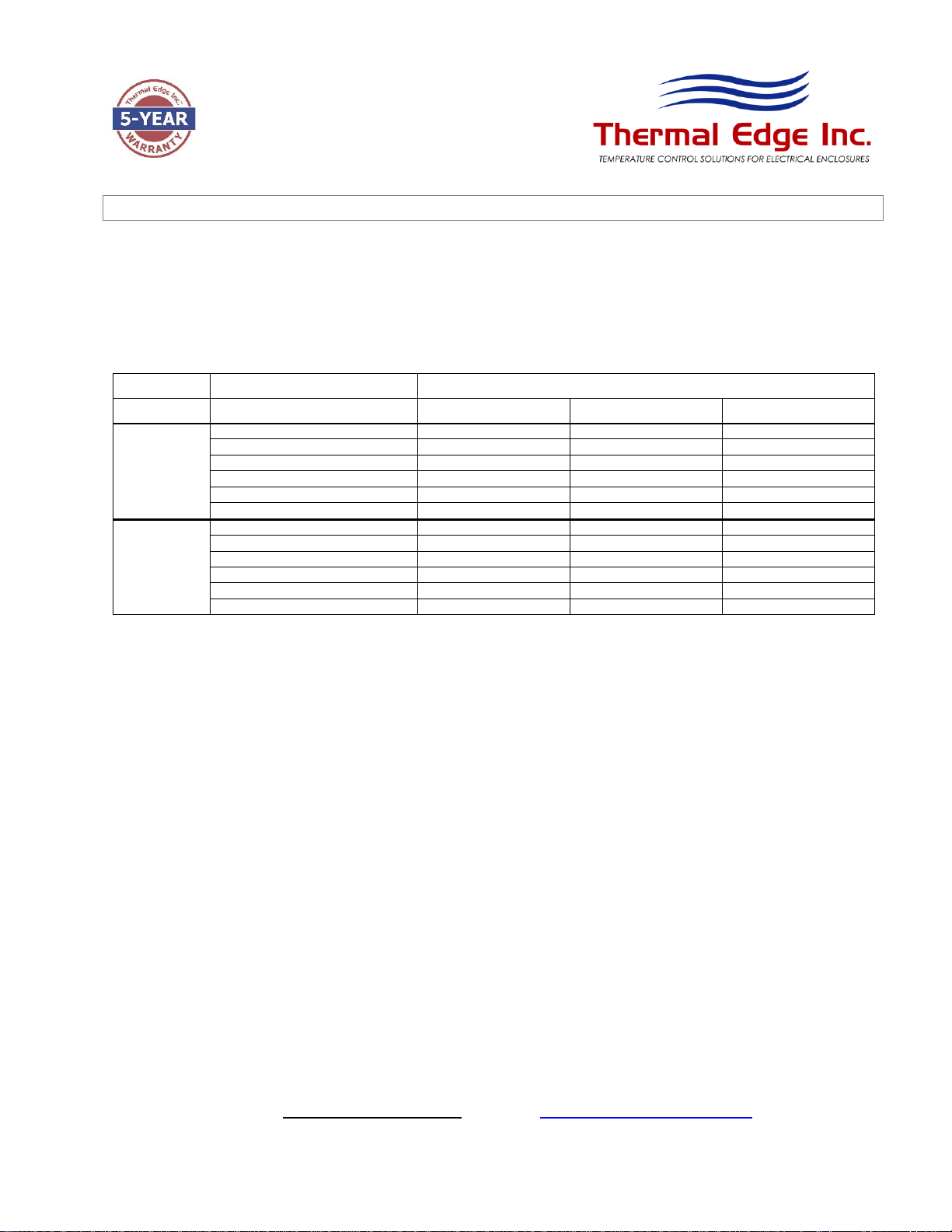
Unit Specifications
The following tables provides electrical and refrigeration specifications for the Air to Water Heat Exchangers.
A2W30 Unit
Nominal Capacity Rating: 3,960 BTUH
Standard Maximum Ambient: 140°F
Unit Weight: 21.4 lbs
Model
Operating
Voltage Range
(Volts)
Loading Current
(Running
Current)
(Amps)
SCCR
(Short Circuit
Current
Rating)
(Amps)
Recommended
Fuse Selection
(Amps)
VA
Rating
A2W30120
103.5-126.5
0.37
*2
15 Amp Class CC,
CCMR Time Delay
*
44
A2W30230
207-253
0.23
*2
15 Amp Class CC,
CCMR Time Delay
*
53
A2W60 Unit
Nominal Capacity Rating: 7,773 BTUH
Standard Maximum Ambient: 140°F
Unit Weight: 34 lbs
Model
Operating
Voltage Range
(Volts)
Loading Current
(Running
Current)
(Amps)
SCCR
(Short Circuit
Current
Rating)
(Amps)
Recommended
Fuse Selection
(Amps)
VA
Rating
A2W60120
103.5-126.5
0.59
*2
15 Amp Class CC,
CCMR Time Delay
*
71
A2W60230
207-253
0.38
*2
15 Amp Class CC,
CCMR Time Delay
*
87
* HACR Type Circuit Breakers or Time-delay Fuses with the following electrical characteristics are recommended. Fast-
acting fuses are not recommended.
% of Ampere Rating
Opening Time
110 %
15min Minimum
125 %
1hr Maximum
200 %
12sec Minimum
4min Maximum
*2 SCCR rating is based on the SCCR rating for the circuit protection device installed in the panel / enclosure per UL50
& UL508a to protect the AC unit. Typically, 100KA –200KA for Time-Delay Fuses.

1800 Hurd Drive ● Irving, Texas 75038 ● (972) 580-0200 ● (888) 580-0202 ● Fax (972) 580-0277
URL: www.thermal-edge.com ● Email: support@thermal-edge.com
SP-ENG-211-000-20 Rev 1.0 9 |P a g e
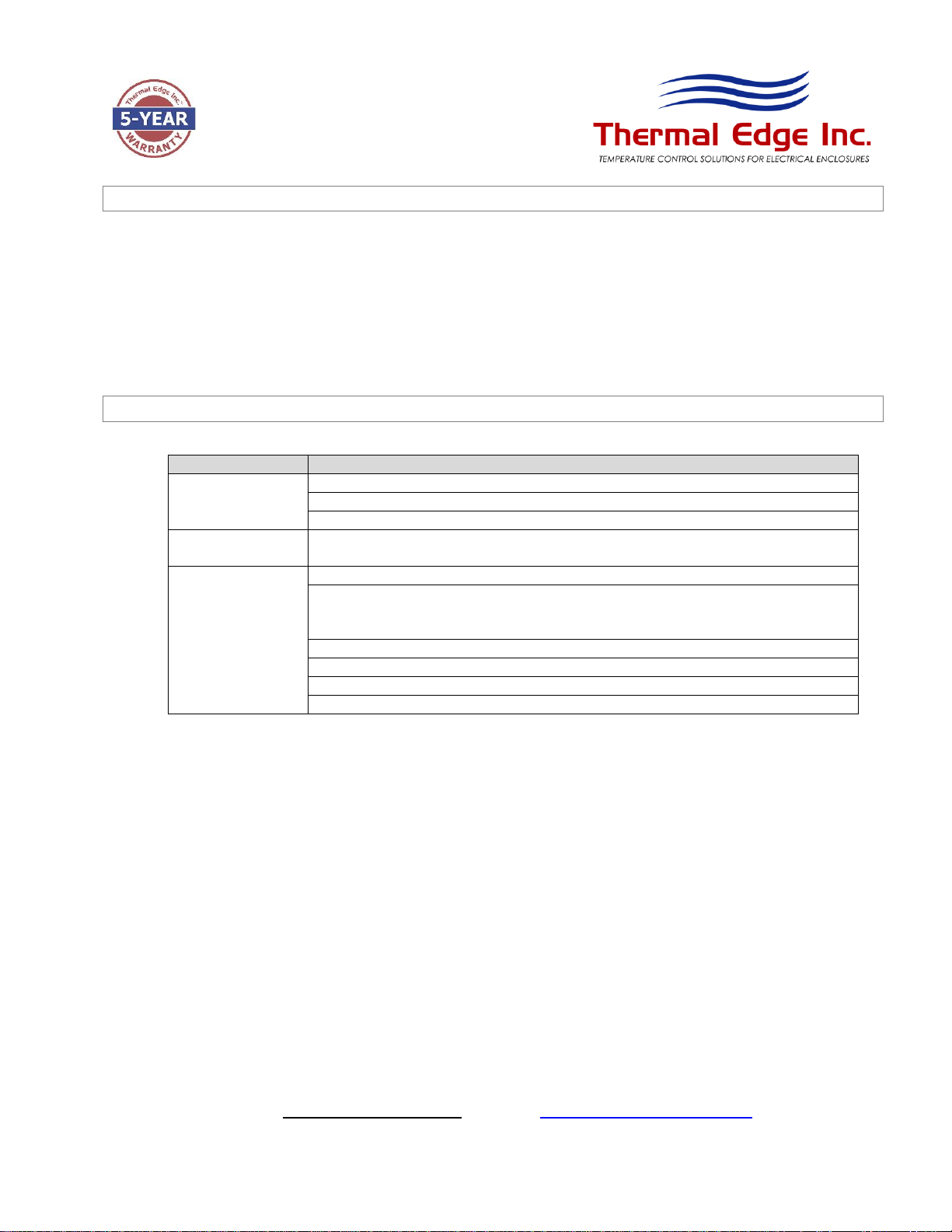
Options
Thermal Edge Air to Water Heat Exchangers may be ordered with the following options. Review the
list below for the specifications and functions of the option(s) that apply to your unit.
Digital Programmable Controller and Solenoid Valve
This option provides a method for customers to control the temperature of their enclosure with a
digital controller as opposed to using their water supply. When this option is selected, the flow of
water through the heat exchanger is managed based on cooling needs.
Dry Contact
This option provides an early warning capability to your enclosure to aid in the protection of your
expensive equipment. The Dry Contact is programmed with an individual dry contact set point to
monitor the enclosure temperature limit that you require. When the enclosure temperature has
exceeded the maximum limit, the Form C gold plated contact will activate to notify you that there is
a problem in achieving your cooling set point.
Default Settings:
•105°F Dry Contact High Temperature Alarm Set Point
At the default settings the Dry Contact initial conditions are normally open and/or normally closed.
When the unit is powered on and the temperature exceeds 105°F for a period longer than 3 minutes
the Dry Contact will activate. At this time the normally open contact will close and the normally
closed contact will open. This state will remain until the temperature has decreased to 103°F.
Note: The dry contact is not a power status indicator, rather a high temperature alarm alerting you
that the unit is unable to meet the cooling set point.
Refer to Advanced Digital Temperature Controller Programming section for details on changing these
parameters.
1800 Hurd Drive ● Irving, Texas 75038 ● (972) 580-0200 ● (888) 580-0202 ● Fax (972) 580-0277
URL: www.thermal-edge.com ● Email: support@thermal-edge.com
SP-ENG-211-000-20 Rev 1.0 10 |P a g e
Celsius Programming
Celsius Programming option allows the user to control the Thermal Edge heat exchanger in SI units. This
feature can be programmed into the digital temperature controller at time of manufacturing.
Special Programming
All Thermal Edge products have a Special Programming option for selecting unique pre in programmed
settings for special requirements. Although most parameters are accessible in our digital controller, this option
allows you to receive a unit preset to your requirements without the need to manually configure the unit. Refer
to Advanced Digital Temperature Controller Programming section for details on all default settings.
1800 Hurd Drive ● Irving, Texas 75038 ● (972) 580-0200 ● (888) 580-0202 ● Fax (972) 580-0277
URL: www.thermal-edge.com ● Email: support@thermal-edge.com
SP-ENG-211-000-20 Rev 1.0 11 |P a g e
System Faults
Thermal Edge Air-to-Water Heat Exchangers are equipped with temperature probes and alarms to
monitor and alert the user of extreme temperature conditions of the water supply and their electrical
enclosure. The conditions that will trigger an alarm on the controller are:
•Enclosure high temperature alarm (default setting 105°F)
•Enclosure low temperature alarm (default setting 45°F)
•Supply water low temperature alarm (default setting 34°F)
•Supply water high temperature alarm (default setting 85°F)
In the event the supply water temperature or enclosure temperatures reaches the low or high
temperature alarm setting, the dry contact relay will close signaling an alarm to the user.
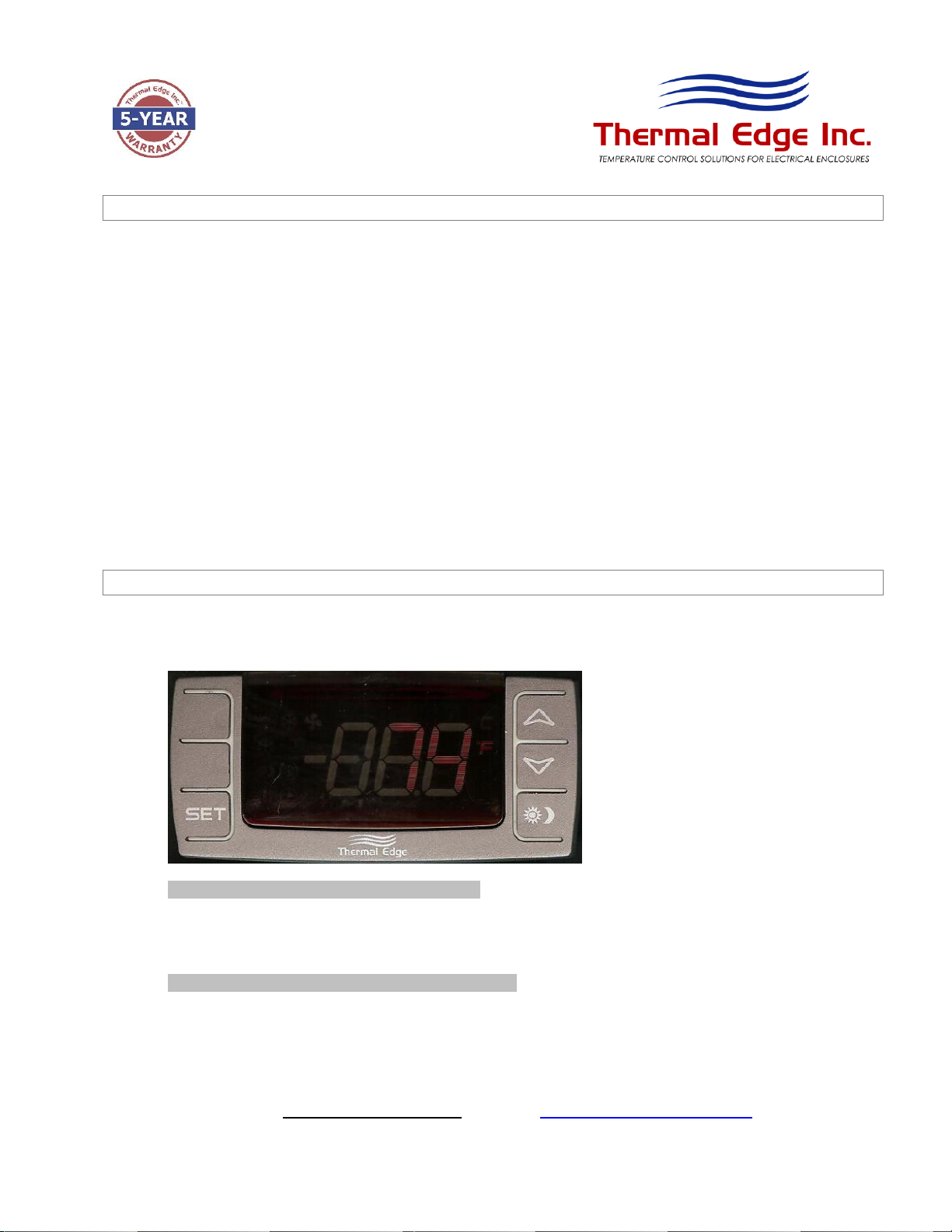
Digital Temperature Controller Programming
For the end user this section will provide all the necessary information to view and change all functions
and parameters available to you.
HOW TO SEE THE SETPOINT……..
1. Press and immediately release the SET key. The display will show the setpoint value.
2. Press and immediately release the SET key or wait for 15 seconds to display the enclosure temperature
again.
HOW TO CHANGE THE SETPOINT……..
1. Press the SET key for more than 2 seconds to change the setpoint value.
2. The value of the setpoint will be displayed and the “F” LED starts blinking.
3. To change the SET value, press the UP or DOWN arrow key within 15 seconds.
4. To store the new setpoint value, press the SETkey again or wait 15 seconds.
1800 Hurd Drive ● Irving, Texas 75038 ● (972) 580-0200 ● (888) 580-0202 ● Fax (972) 580-0277
URL: www.thermal-edge.com ● Email: support@thermal-edge.com
SP-ENG-211-000-20 Rev 1.0 12 |P a g e
Note: The set value is stored even when the procedure is exited by waiting for the time-out to expire.
HOW TO ACCESS HIDDEN MENU 1……..
1. Enter the Programming mode by pressing the SET + DOWN arrow keys simultaneously for 3 seconds.
The “F” LED starts blinking.
2. Select the required parameter by pressing the UP or DOWN arrow key. Press the SET key to display
its value.
3. Use the UP or DOWN arrow key to change its value.
4. Press SET to store the new value and move to the following parameter.
To exit: Press SET + UP arrow keys or wait 15 seconds without pressing a key.
Note: The set value is stored even when the procedure is exited by waiting for the time-out to expire.
HOW TO ACCESS HIDDEN MENU 2……..
1. Enter the Programming mode by pressing the SET + DOWN arrow keys simultaneously for 3 seconds.
The “F” LED starts blinking.
2. Release the keys, then push the SET + DOWN arrows keys simultaneously, again for more than 7
seconds.
The Pr2 label will be displayed immediately followed by the HY parameter.
3. Select the required parameter by pressing the UP or DOWN arrow key. Press the SET key to display
its value.
4. Use the UP or DOWN arrow key to change its value.
5. Press SETto store the new value and move to the following parameter.
To exit: Press SET + UP arrow keys or wait 15 seconds without pressing a key.
Note: The set value is stored even when the procedure is exited by waiting for the time-out to expire.
HOW TO LOCK THE KEYPAD……..
1. Press and hold the UP and DOWN arrow keys simultaneously for more than 3 seconds.
2. The POF message will be displayed and the keyboard will be locked.
At this point, it will be possible only to see the setpoint or the MAX or MIN temperature stored.
3. If a key is pressed for more than 3 seconds the POF message will be displayed.
HOW TO UNLOCK THE KEYPAD……..
1. Press and hold the UP + DOWN arrow keys simultaneously for more than 3 seconds until the Pon
message is displayed.
1800 Hurd Drive ● Irving, Texas 75038 ● (972) 580-0200 ● (888) 580-0202 ● Fax (972) 580-0277
URL: www.thermal-edge.com ● Email: support@thermal-edge.com
SP-ENG-211-000-20 Rev 1.0 13 |P a g e
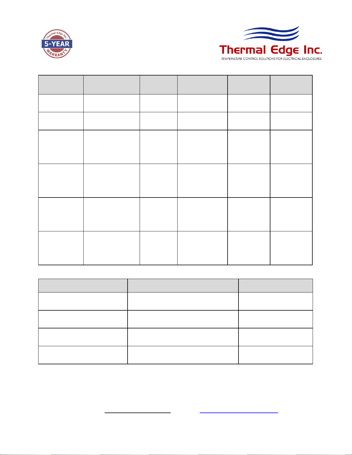
Functions and Parameters
Function
Operation
Parameter
Menu Location
Factory
Default
Unit
Cooling Setpoint
Set Desired Cooling
Temperature
SET
Main
90
°F
Cooling
Differential
Control Hysteresis
Hy
Hidden Menu 1
2
°F
Maximum
Enclosure
Temperature
Alarm
Alerts with “HA”
when enclosure
temperature has
exceeded maximum
value
ALU
Hidden Menu 2
105
°F
Minimum
Enclosure
Temperature
Alarm
Alerts with “LA” when
enclosure
temperature has
exceeded minimum
value
ALL
Hidden Menu 2
45
°F
Maximum
Supply Water
Temperature
Alarm
Alerts with “HA2”
when supply water
temperature has
exceeded maximum
value
AU2
Hidden Menu 2
85
°F
Minimum
Supply Water
Temperature
Alarm
Alerts with “LA2”
when supply water
temperature has
exceeded minimum
value
AL2
Hidden Menu 2
34
°F
Alarm Signals
Message
Cause
Actions
“HA”
Maximum Temperature Alarm: Enclosure
temperature > 105°F
No Action/Alarm Only
“LA”
Minimum Temperature Alarm: Enclosure
temperature < 45°F
No Action/Alarm Only
“HA2”
Maximum Temperature Alarm: Supply water
temperature > 85°F
No Action/Alarm Only
“LA2”
Minimum Temperature Alarm: Supply water
temperature < 34°F
No Action/Alarm Only

1800 Hurd Drive ● Irving, Texas 75038 ● (972) 580-0200 ● (888) 580-0202 ● Fax (972) 580-0277
URL: www.thermal-edge.com ● Email: support@thermal-edge.com
SP-ENG-211-000-20 Rev 1.0 14 |P a g e
Alarm Recovery
•Temperature alarm HA automatically clears as soon as the enclosure temperature returns to 103°F
(ALU set point - 2°F).
•Temperature alarm LA automatically clears as soon as the enclosure temperature returns to 47°F
(ALL setpoint + 2°F).
•Temperature alarm HA2 automatically clears as soon as the supply water temperature returns to
below 85°F.
•Temperature alarm LA2 automatically clears as soon as the supply water temperature returns to
above 34°F.

1800 Hurd Drive ● Irving, Texas 75038 ● (972) 580-0200 ● (888) 580-0202 ● Fax (972) 580-0277
URL: www.thermal-edge.com ● Email: support@thermal-edge.com
SP-ENG-211-000-20 Rev 1.0 15 |P a g e
Preventative Maintenance
Refer to Field Serviceable Parts section in this manual for details on parts that can be changed to help
increase the uninterruptable life of the Heat exchanger.
To avoid frost damage, the minimum permissible water temperature of 34°F (+1°C) must be complied with at
any point in the water cycle. Any damage due to freezing is not covered by the warranty.
During storage at temperatures below water freezing temperatures and transportation, the water should be
completely drained from the heat exchanger to prevent damage to coil. Disconnect the water lines and use
compressed air to remove all water.
Thermal Edge heat exchangers use high efficiency, long life, sealed ball bearing fans engineered for optimum
performance that require no maintenance. Keep fan blades clean for optimal performance. Fans are
removable and attached by plug in connections.
Note: Do no use solvents to clean the digital controller when supplied. Wipe with mild soap and water.
1800 Hurd Drive ● Irving, Texas 75038 ● (972) 580-0200 ● (888) 580-0202 ● Fax (972) 580-0277
URL: www.thermal-edge.com ● Email: support@thermal-edge.com
SP-ENG-211-000-20 Rev 1.0 16 |P a g e
Field Serviceable Parts
Thermal Edge carefully designs and selects components with the maximum life expectancy. Due to OEM
manufacturing tolerances, poor unit maintenance or extreme operating conditions, components may fail before
their maximum life expectancy. The table below lists parts that are serviceable in the field by a heat exchanger
technician.
Unit
Part Description
Thermal Edge Part #
115VAC
230VAC
460VAC
A2W30
Digital Controller
52110-1
52112-1
52110-1
Solenoid Valve
33000-1-1
33000-2-1
33000-1-1
Temperature Probe, 1.5m
52126-2-2
52126-2-2
52126-2-2
Temperature Probe Mounting Clip
52126-500C
52126-500C
52126-500C
Gasket Installation Kit
71440-A2W30
71440-A2W30
71440-A2W30
Fan
41005-1-2
41005-2-2
41005-1-2
A2W60
Digital Controller
52110-1
52112-1
52110-1
Solenoid Valve
33000-1-1
33000-2-1
33000-1-1
Temperature Probe, 1.5m
52126-2-2
52126-2-2
52126-2-2
Temperature Probe Mounting Clip
52126-500C
52126-500C
52126-500C
Gasket Installation Kit
71441-A2W60
71441-A2W60
71441-A2W60
Fan
41037-1-2
41037-2-2
41037-1-2
1800 Hurd Drive ● Irving, Texas 75038 ● (972) 580-0200 ● (888) 580-0202 ● Fax (972) 580-0277
URL: www.thermal-edge.com ● Email: support@thermal-edge.com
SP-ENG-211-000-20 Rev 1.0 17 |P a g e
Safety Information
Unit is carefully designed to restrict access to movable parts to minimize any potential injury. This Heat
exchanger has been tested by UL to meet the safety requirements of the UL484 specification. When working
with the Thermal Edge Heat exchanger always makes sure shroud is installed. Verify proper voltage is
applied to unit as specified in the UL label of the Heat exchanger. In the event of a field service repair, power
down unit using the power on/off switch and disconnect power from unit. It is always recommended to use a
licensed heat exchanger technician for internal diagnostics and repairs issues.
Contact Thermal Edge technical support for further details on opening the unit and troubleshooting tips.
Troubleshooting Guide
SYMPTOM
POSSIBLE CAUSE
Unit will not run
Check that the power is connected
Verify that power switch is in ON position
Verify that input power meets voltage requirements shown in UL label
Fan is not
working
Fan faulty –Replace the fan
The fan is
working, unit is
not cooling
Controller set point is set too high –Adjust set point
Insufficient water flow –Check that the flow rate corresponds to the
prescribed flow
rate on the unit nameplate
Controller faulty –Replace controller
Solenoid valve faulty –Replace solenoid valve
Water temperature too high –Adjust the water temperature
Obstructed airflow in enclosure –Remove airflow blockage


1800 Hurd Drive ● Irving, Texas 75038 ● (972) 580-0200 ● (888) 580-0202 ● Fax (972) 580-0277
URL: www.thermal-edge.com ● Email: support@thermal-edge.com
SP-ENG-211-000-20 Rev 1.0 20 |P a g e
Warranty Information
Thermal Edge products are warranted to be free of defects in workmanship, materials and components. The warranty
period applies from date of shipment for five years. Replacement components have a one year warranty period,
except for hermetic system components, which have a 90 day warranty period.
The above warranty applies when the equipment is operated under the following conditions:
•Ambient temperature not in excess of performance rating in normal atmosphere or as stated on product
nameplate
•Voltage variation within limits stated in User & Technical Manual
•Frequency variation no greater than ± 3Hz from nameplate rating
•Maximum cooling load no higher than heat exchanger nameplate rating
•Compliance to all other installation, maintenance and operating instructions, as supplied
Thermal Edge cannot assume responsibility for misapplication of its products or the erroneous selection of an
inappropriate product by a non-authorized Thermal Edge representative. Our applications engineers will gladly assist
in the selection of the proper product provided all required details of the application are furnished.
Thermal Edge assumes no liability beyond the repair or replacement of its own product. This Warranty does not
cover:
•Labor or reimbursement of labor for evaluation, removal, installation, repair, or cost of any warranted part,
except at the Thermal Edge factory in Dallas, Texas
•Use of equipment for other than its designed purpose or operating conditions
•Operation in harsh, oily, corrosive or other abnormal environmental conditions, without the proper filtration,
sealing, protective coatings and/or weather protection, or cosmetic corrosion that does not affect operation
•Improper or negligent maintenance
•Damage resulting from untreated or improperly treated water, or saline or brackish water.
•Customer modification or abuse
•Shipping damage or other accident
•Repair or service by unauthorized personnel.
Thermal Edge must be notified of a claim in writing not later than fourteen (14) days from the date when buyer has
become aware of such occurrence, or immediately, when the defect is such that it may cause damage.
If heat exchanger is to be shipped or transported at any time, it is best to pack in original packaging and strap to
pallet to prevent damage. Heat exchangers that have internal damage due to shipping are not covered under the
Warranty. Claims for shipping damage are the responsibility of the Consignee. Damage must be noted on Bill of
Lading at time of receipt. Timely claims must be filed with the freight carrier.
The purchaser assumes the responsibility of grounding the unit and installing it in accordance with local electrical and
safety codes, as well as the 2008 National Electric Code (NEC) and OSHA.
THIS WARRANTY CONSTITUTES THE ENTIRE WARRANTY WITH RESPECT TO THE PRODUCT AND IS IN LIEU
OF ALL OTHERS, EXPRESSED OR IMPLIED, INCLUDING ANY WARRANTY OF MERCHANTABILITY AND
WARRANTY OF FITNESS FOR A PARTICULAR PURPOSE AND IN NO EVENT IS THERMAL EDGE
RESPONSIBLE FOR ANY CONSEQUENTIAL DAMAGES OF ANY NATURE WHATSOEVER.
This manual suits for next models
3
Table of contents


