Flexiheat FH50ECP User manual
1
02/04/2019Page
INSTALLATION INSTRUCTIONS
Wood Warm Air Heaters
FH50ECP and FH100ECP
Please read carefully the precautions for use and the instructions for use before any installation andcommissioning.
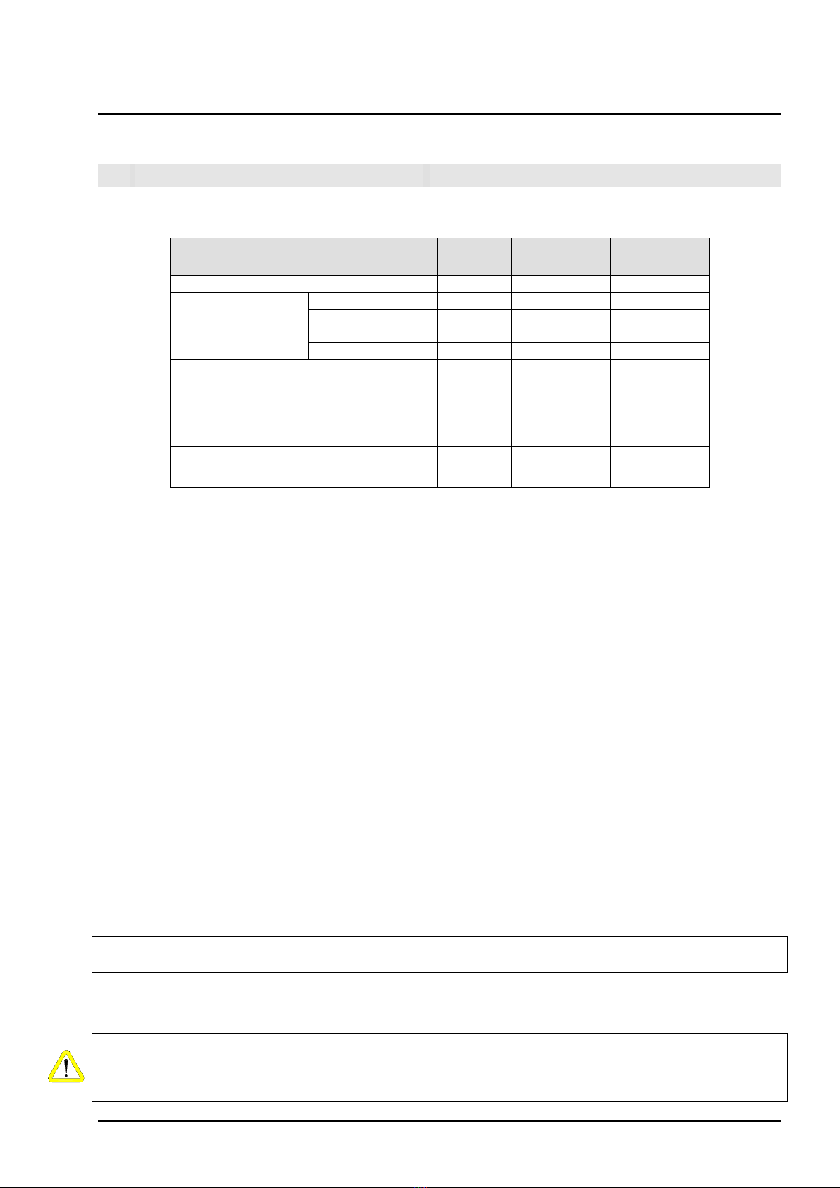
Nominal thermal power kW 50 100
Flow at + 20ºC m3/ h 1700 3,400
TREATED AIR Static pressure
useful
mm.ca 5 5
Thermal jump º C 45 45
Number of fans Nº 1 1
rpm 900 900
Electric tension V 230 230
Weight Kg. 240 440
Maximum load (dry wood) Kg. 10 20
Hearth Dimensions (Long, Wide, High) cm 83x50x60 115x70x65
Hatches Dimensions (Long, Wide) cm 64x28 89.2x28
Heating power dry wood = 4000 kcal / kg
• Recommendations
-Carefully read the warnings that appear in the instructions, knowing that they contain important
according to the manufacturer's instructions, by professionally qualified personnel or by a technical platform
approved by the manufacturer. An error during installation can cause damage and risks to people and
equipment, for which the manufacturer cannot be held responsible.
-Check the packaging and the integrity of the contents. If in doubt, do not use the device and contact the
distributor or the manufacturer.
-Do not leave the packaging elements within the reach of children, as they represent a source of
danger.
-Keep the suction grilles free.
-In the event of a breakdown or malfunction of the appliance, unplug it, refraining from any attempt
to repair it, and contact your distributor.
-As soon as you decide to stop using the appliance, you must not use parts that could constitute a
-Make sure that these instructions are always included with the device.
-The regulatory protection of the device must be ensured in accordance with the classification standards for the
professional premises where it is installed.
If the appliance is installed in a place where there are disabled people and / or accompanied by
children, it must be installed with protections in accordance with the regulations in force.
In the event of overloading: Risk of deformation of the floor crosspieces and cracks in the
brickwork Damage to the exchanger tubes, temperature rise, general deformation and damage to
the device.
2
02/04/2019
FH50ECP FH100ECP
1TECHNICAL CHARACTERISTICS:
Page
Never load more than 10 kg of log wood or briquettes for FH50ECP and 20Kg for FH100ECP, i.e. 50
and 100 kW.
source of danger.
-This appliance must be used for the use for which it is intended. Any other use will be considered inadequate and,
if necessary, dangerous, relieving the manufacturer of responsibility and thereby voiding the manufacturer's
warranty.
indications relating to the safety of the installations, their use and maintenance.
-Use wood as a priority to ensure good combustion of Heater.
-The installation must be carried out according to the standards in force in the country where it will be used,
This hot air generator works with solid vegetable fuels; it is a device whose operating principle is
the production of direct heat through the use of thermal energy produced by combustion.
Heat exchange is produced when a flow of air generated by a fan is passed through the internal
surfaces of the heat exchanger, without the aid of any intermediate fluid so called direct
exchange. In addition, part of the thermal energy is produced by the low temperature radiation of
the machine.
The gaseous residues resulting from the combustion (fumes), when the heat exchange is carried out,
are expelled outside through the flue gas pipe at a temperature of approximately 280 ° C at maximum
developed power.
The solid residues of gasoline combustion (ash) fall naturally thanks to a stainless steel grate in an
ashtray drawer in the lower part.
This appliance is used for heating industrial environments and meets these standards. It can also
be used for any other application, in this case, refer to the specific standards.
To) A rectangular-shaped combustion chamber briquetted by refractory elements.
b) A tilting hatch for loading solid fuels.
vs) A tubular heat exchanger with a large surface area with natural ventilation fairing.
d) A perforated ash collection drawer with adjustable primary combustion air intake ruler.
e) A chimney nozzle fitted with a draft key through which the combustion residues pass to be
expelled through the smoke duct outside the heated enclosure.
• Ventilation group
The device is equipped with a medium pressure centrifugal fan which allows the connection of a
distribution duct.
• Chimney nozzle
The appliance is equipped with a circular outlet of a standard diameter where it is possible to connect and
securely fix a metal flue (preferably insulated) to evacuate the gaseous residues resulting from the
combustion to the outside. The draft key integrated into the nozzle allows the power to be regulated by
limiting the natural depression.
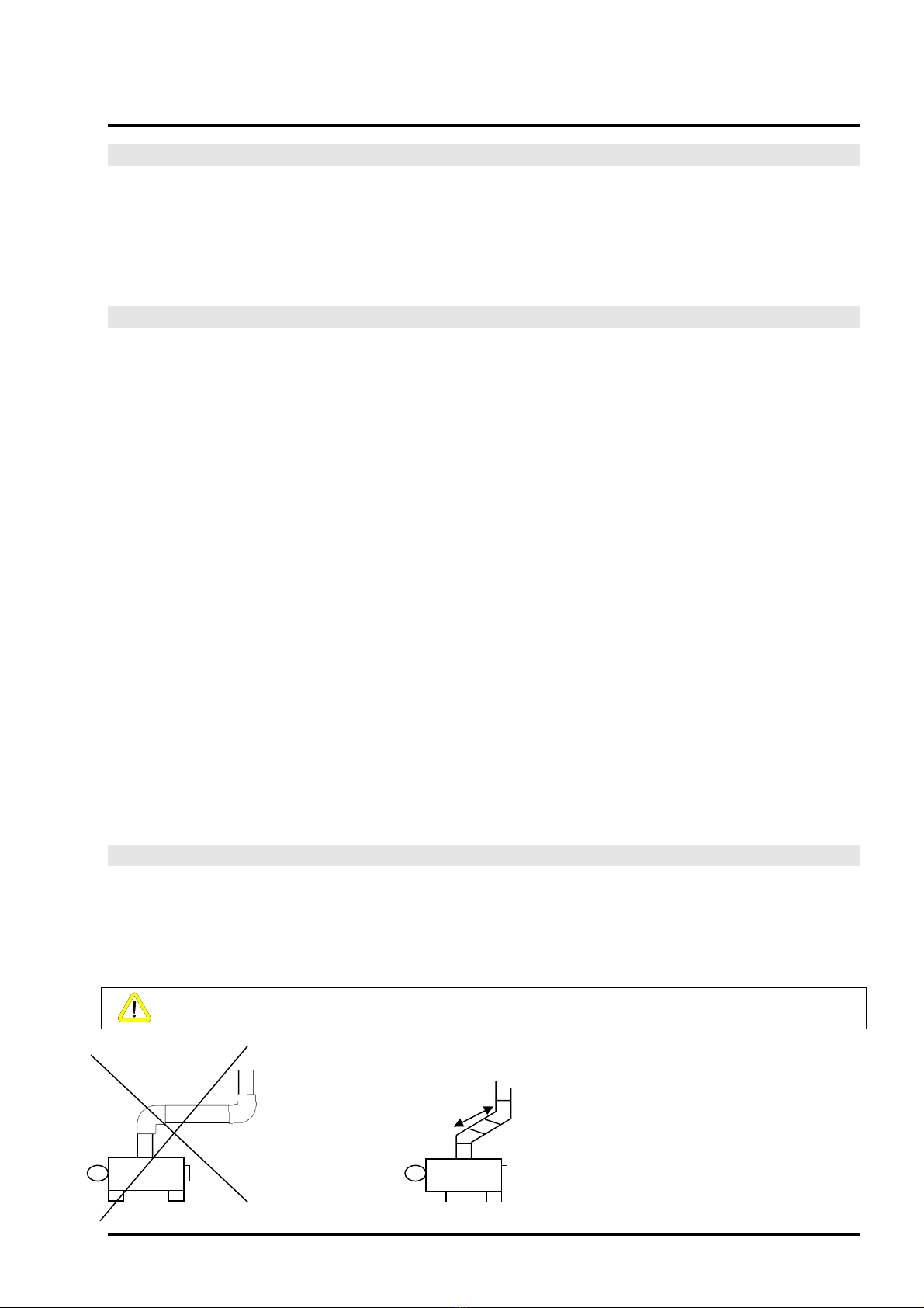
This duct must have the following characteristics:
• Do not add elbows with more than a 45 ° angle and raise the duct in this case by 1m per 45 °
elbow
• Have an end part of the duct fitted with a cap.
3
02/04/2019
1.1 PRINCIPLE OF FOOPERATION:
2CONSTRUCTION OF THE APPLIANCE:
• Diameter equal to or greater than the nozzle of the device and without section reductions. (Ø 153 mm
for FH50ECP and Ø 200 mm for FH100ECP)
Page
The heater is made of carbon steel sheet, developed according to European standards. Easy
to access for normal cleaning and maintenance operations. It is composed of :
It cannot be installed in direct contact with explosive agents or in a flammable
environment.
Hot air generators are shipped with plastic bubble wrap. The accessories are packed separately in
cardboard packaging. Transport and unloading must be carried out with great care to avoid
possible damage. Before accepting the packages, it is advisable to unpack the equipment in the
presence of the carrier in order to ascertain the condition of the goods and therefore to avoid any
dispute.
- Provide a safety distance of at least 1 meter from any obstacle around the device.
- Do not obstruct the fan's suction grilles.
- Check that no obstacle hinders the distribution of hot air.
- Make sure that maintenance and cleaning operations can be carried out easily.
• Electrical connection
The device must be installed in accordance with all standards and laws in force in the
geographical area of use of the device.
The installed chimney will comply with the regulations relating to its use and will have a draft
regulator. This duct will be insulated as far as possible in double skin to avoid the dew point. (1m
after the discharge nozzle). We offer an optional STAINLESS STEEL starter kit with buffer to
facilitate maintenance by relocating the duct.
Never horizontal part with 90 ° elbows
Elbow
open 45 °
Elbow
90 °
Elbow
90 °
- 1m
Elbow
open 45 °
NO YES
4
02/04/2019
2.1 PACKAGING AND TRANSPORT:
2.2 INSTALLATION INSTRUCTION:
The position of the wood heaters must be defined by considering the following indications:
• Installation protocol
- Position of the device level, stably installed on a slab made for this purpose.
2.3 COMBUSTION GAS EVACUATION:
Page
This device has been manufactured according to the EEC 73/23 directive and operates under a
current of 240V single phase 50Hz.
• Key and draft moderator
- To regulate the draft, it is essential to install a draft moderator on the flue gas pipe
- In order to regulate combustion, a regulation key is integrated on the flue gas nozzle which
will limit combustion when the generator is fully loaded and reduce combustion in order to
increase autonomy, particularly at night.
DRAW
The draft of a chimney is determined by the following formula:
T = H (YA - YB)
T = Draft in mm.ca
H = Height of the vertical chimney in meters. YA =
Specific weight of the outside air in kg / m³.
YB = Specific weight of the combustion gases expelled in kg / m³.
SECTION
The section of the chimney for the two series is determined by the following formula:
S = 8.61 Q / H½
S = Section of the chimney in cm²
Q = This is the power of the boiler in kW / h. H =
The reduced height expressed in meters.
The reduced height of the chimney is defined by the following formula:
Hr = H - (N. 0.5 + L + R)
Hr = Reduced height
H = Actual height of the chimney. N
= Number of elbows.
L = Horizontal length.
R = Generator back pressure.
R = 1mm up to 50,000 kcal / h. R =
2mm up to 160,000 kcal / h.
NOTE: These values must be increased by 6% depending on the region for every 500
meters of elevation above sea level.
DUCT DEPRESSION
The draft measurement must be carried out under the shutter, which will allow the shutter to be
balanced during the measurement.
The flue gas pipe must never be reduced to a diameter smaller than that of the
outlet nozzle. However, there is no problem if the duct is of a larger diameter. In the
event of installation on an old masonry duct, it is essential to pipe the duct.
5
02/04/2019Page
During installation, at the time of commissioning, it is recommended to have a draft
measurement called "depression" carried out in order to check the water column of the
chimney's depression.
This measurement is carried out while hot when the device is at its normal output after
approximately half an hour of operation.
This depression should be 2 mm WC after the pull key.
It is therefore recommended for this result a vertical height of 5m for an FH50ECP and 6
to 7m for an FH100ECP.
In order to stabilize the draft, it is necessary to install at the outlet of the Ø 153mm nozzle for
FH50ECP and 200mm for FH100ECP, a tee fitted with a regulator flap.
If you notice after several hours of use that smoke is coming out of the
the sides of the loading hatch closed, the duct does not have enough draft. It must
therefore be enhanced. It is imperative that the duct exceeds at least 50 cm the
highest point of the roof called "ridge" and in any case, higher than 50 cm of any
obstacle around the duct. (building nearby)
The chimney will be insulated and will never have a horizontal part according to the
regulations in force.
Depending on the regulations in force in the geographical area concerned, it may
be necessary to install particle filtration on the smoke evacuation network.
In the event of an electrical fault or fan malfunction, first make sure that:
• The power supply is correct.
• There are no voltage variations greater than + 10% or -15%.
• The fuses are in good condition.
• There is no shortage of solid fuel.
NOTE: Any repairs must be carried out by qualified technical personnel using original
spare parts. It is forbidden to open or manipulate the components of the generator, with
the exception of those provided for maintenance.
NEVER TURN ON THE GENERATOR WITHOUT CONNECTING THE
ELECTRIC NETWORK FAN
NEVER DISCONNECT THE POWER WHEN THE APPLIANCE IS HOT
Since the thermal energy accumulated in the combustion chamber and the heat exchanger
can damage the electric fan unit and the heat exchanger.
DO NOT TOUCH THE PARTS EXPOSED TO HEAT RADIATION in particular the
loading door, the nozzle and the uninsulated duct.
WARNING :
It is imperative to keep a respectable distance when opening the hatch to avoid
any risk of burns.
6
02/04/2019
2.4 IRREGULARITIES IN OPERATION AND PRECAUTIONS
CAUSES AND SOLUTIONS
Page
3 - Deterioration of the steel or carbon heat exchanger tubes 4
- Perforation of the walls or heat exchanger tubes
5 - Deterioration of the high temperature coating
• Ventilation in summer
To obtain ventilation only from the generator, proceed as follows: Switch the
inverter to the summer position.
For normal operation and proper aging of the device over time, it is regulatory that qualified
technical personnel carry out, at least once a year and preferably at the end of the season,
annual maintenance operations, including including the sweeping of the flue. In the event of a
claim, the insurance company will request the annual certificate of chimney sweeping carried
out by a professional.
Any work on the device must be carried out cold.
• Cleaning the exchanger at the end of the season
Proceed as follows:
- Unscrew the exchanger / fireplace assembly bolts
- Remove the exchanger
- Clean the outside of the heat exchanger tubes, if necessary by steam washing using a high
pressure cleaner.
- Empty and clean the ash drawer
- Vacuum the soot in the combustion chamber, clean the brickwork
- Periodically replace damaged bricks (see spare parts list).
• Maintenance of the flue gas pipe
Disassemble the duct components and carefully sweep the flammable deposit film.
• Electric fan unit
Blow out the inside of the engine with compressed air.
Use a brush and compressed air to clean the fan blades
7
02/04/2019
2.5 MAINTENANCE:
Page
Any load greater than the maximum load corresponding to the power of the
device, i.e. 10 kg for FH50ECP and 20 kg for FH100ECP, irreparably implies
overheating of the device in the short term, which causes damage:
1 - The crack in the refractory brickwork
2 - Deformation of the floor cross members which support the INOX floor grid.
This deformation gradually causing the impossibility of opening the ash drawer.
Improper installation of the flue gas can cause the same damage caused by
overheating of the lower part of the appliance due to the lack of draft.

This device is intended for the heating of industrial buildings, or others in compliance
with legislation, safety and fire.
It cannot be installed in direct environmental contact with explosive agents (paints,
solvents, etc.).
The device must be installed in accordance with all standards and laws in force in the
geographical area of use of the device.
After these 2 operations, the stove can be loaded normally.
• Device shutdown at the end of the season
Disconnect the device and carry out maintenance (Paragraph 9).
10Kg of bricks = 50 Kw or 5 Kw per kg of bricks. A standard brick has an average weight of 1.8
kg, or 9 kW of energy.
8
02/04/2019
2.6 COMMISSIONING AND USE OF THE APPLIANCE:
• Use
Page
Note: If these operations are not carried out, there is a risk of cracking certain elements of the
brickwork.
CAUTION: never shock the briquetting at high temperature when filling (risk of cracking the
briquetting elements).
• Firing refractory briquetting at first use
When using for the first time, it is essential to carry out the briquetting firing procedure so
that it takes on its refractory characteristics.
To do this, during the first commissioning,
Connect the fan to the 240V + T electrical network, load the fireplace to 30% of its capacity, i.e.
around 3 to 4 kg with low-density wood, but with rapid combustion of species (wood from pallets,
poplars, offcuts, wooden logs ...)
After the total combustion of this charge, repeat the operation with 50% of the charge (draft key
open to the max.)
• Commissioning after briquetting
- Load the appliance with wood or any other non-polluting solid fuel (for FH50ECP with a
maximum of 10kg, for wood, which represents a combustion of 50KW / for FH100ECP with a
maximum of 20Kg, for wood, which represents a combustion of 100Kw)
- Connect the fan to the 240V + T electrical network.
- Light the selected wood or solid fuel.
- The fuel load must never exceed the rated power of the heater. Do not start the heater without
connecting the fan to the electrical network.
• Fuel (concerns FH50ECP)
The calorific value of dry wood is about 10 kg or (4.7 kW to 5.3kW per kg) 50 kW at 45/50 °
humidity.
The filling for 50 Kw is therefore 10Kg
Each time the wood heater is put into service, it must be lit with a first load of wood in order to
obtain active embers
When reloading, it is possible to incorporate chips or chip brick. The compressed chip brick can be
used for reloading. It is advisable to incorporate a briquette by validating the total load weight
given the high calorific value of the reconstituted briquette.

Smoke outlet
with pull key
Draft regulation key
Group
electro-fan
Fairing
exchanger
heat
Brickwork
refractory
ground
Hopper
air distribution
Door of
loading
Drawer
collection ofRoom of
combustion
9
02/04/2019
2.7 EXPLODED VIEW OF THE UNIT:
Stainless steel grid
Page
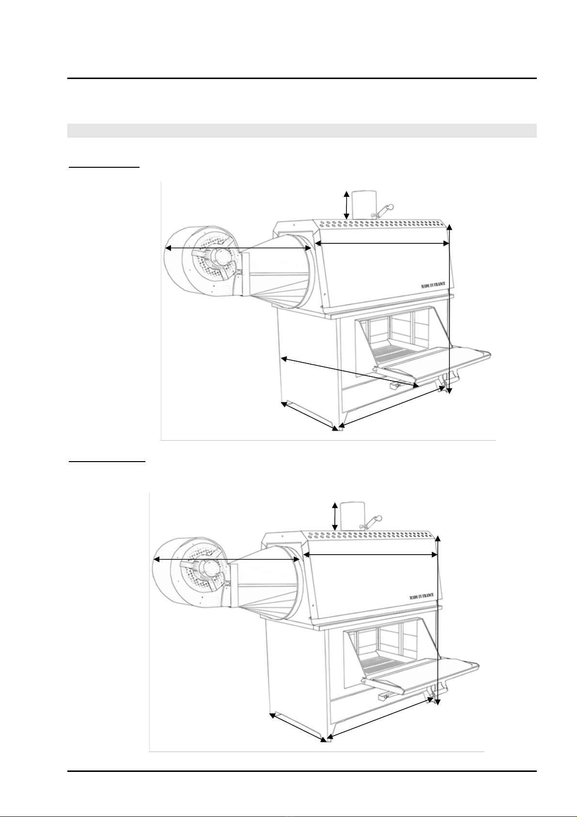
180 mm
700 mm
1110 mm
1180 mm
780 mm
620 mm 970 mm
182 mm
900 mm
1286 mm
1790.50 mm
845 mm 1340.50 mm
10
02/04/2019
2.8 DIMENSIONS:
Page
Model FH50ECP
Model FH100ECP
The fan regulation allows the fan to be started up at the set temperature (i.e. around 30 ° C). As soon as
the thermal heating circuit is at this temperature, the fan will start up (inverter in winter position). When
the appliance cools down, the fan will stop at the set temperature in order to prevent the circulation of
fresh air during the mass heating cycle.
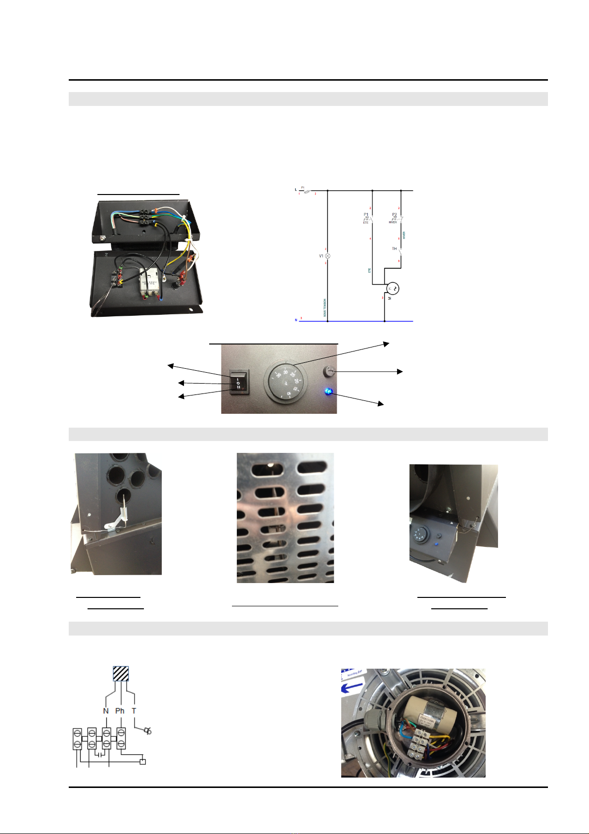
Electrical cabinet
V1: Indicator
voltage presence
P2: Inverter
summer Winter
Th: Thermostat
fan
Description of the dashboard Thermostat
Summer
Fuse
Stop
Winter Voltage presence indicator
Probe position
thermostatic
Passage of the probe
thermostatic
Position behind the grid
In the 220 V mono motor connection box
Power cable
departure from the cabinet
Earth lug
11
02/04/2019
2.9 DESCRIPTION, CABINET OPERATION (OPTIONAL) AND DIAGRAM
2.10 POSITIONING OF THE ELECTRICAL CABINET AND THE PROBE
2.11 FAN CABLE CONNECTION DIAGRAM
Page
Assembly
Position the thermometer in the housing provided for this purpose in the chimney nozzle
12
02/04/2019
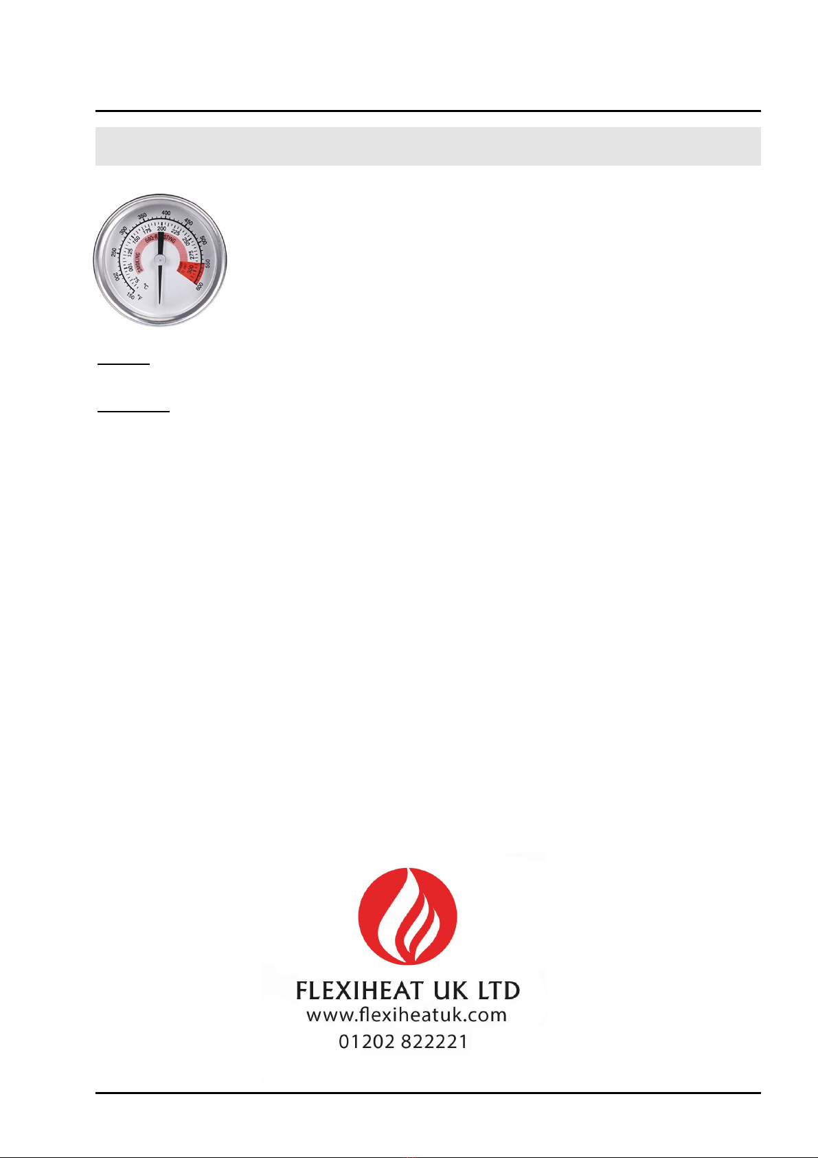
2.12 DESCRIPTION AND OPERATION OF THE VISUAL THERMOCONTROLE
(OPTION)
Indeed, at full power, the flue gas temperature is around 270 ° for a compliant
chimney installation (2mm / cc of depression)
The visual thermo-control is a thermometer which allows to control
the power produced according to the loading, that is to say 10 kg of
wood for the model FH50ECP or 20 kg of wood for the model
FH100ECP.
Page
At 50% power, i.e. around 150 ° C, you can reload the wood heater with fuel to develop the maximum
power, i.e. 5 kg for the FH50ECP or 10 kg for the FH100ECP, of additional fuel.
Functioning
As soon as the vegetable fuel is burnt, the flue gas temperature is indicated on the visual thermal
control.
The maximum power can be viewed by the red zone of the thermometer dial at 280°
In the event of overheating, spread the fuel in the fireplace and allow the temperature of the flue
gases to drop below 270°
This manual suits for next models
1
Table of contents
Other Flexiheat Heater manuals


Popular Heater manuals by other brands


Thermon
Thermon Caloritech EX Series Installation, operation & maintenance instructions

Truma
Truma Combi operating instructions

Everdure
Everdure HPE221W Operation, maintenance and safety instructions

Frico
Frico IR3000 Original instructions

Midea
Midea NF20-16BA instruction manual

Sealey
Sealey CD2005T.V2 instructions