Flexiheat LEO EL S BMS User manual

LEO
EL S | L BMS

TABLE OF CONTENTS
1. Application...................................................................................... 2
2. Technical Data ............................................................................... 3
3. Installation ...................................................................................... 5
3.1. Installation – bracket ............................................................... 5
3.2. Assembly instructions.............................................................. 5
3.3. U-profiles (optional) ................................................................. 5
4. Connection diagrams...................................................................... 6
5. Start-Up and Operation................................................................... 8
6. Service and warranty terms .......................................................... 10
7. Conformity with WEEE directive 2012/19/UE................................ 12
1. APPLICATION
LEO EL heaters make up a decentralised heating system. Fan heaters
are used for heating large volume buildings: general, industrial and
public buildings etc. The devices are designed for indoor use where
maximum air dustiness does not exceed 0,3 g/m
3
.
2 |
| 3
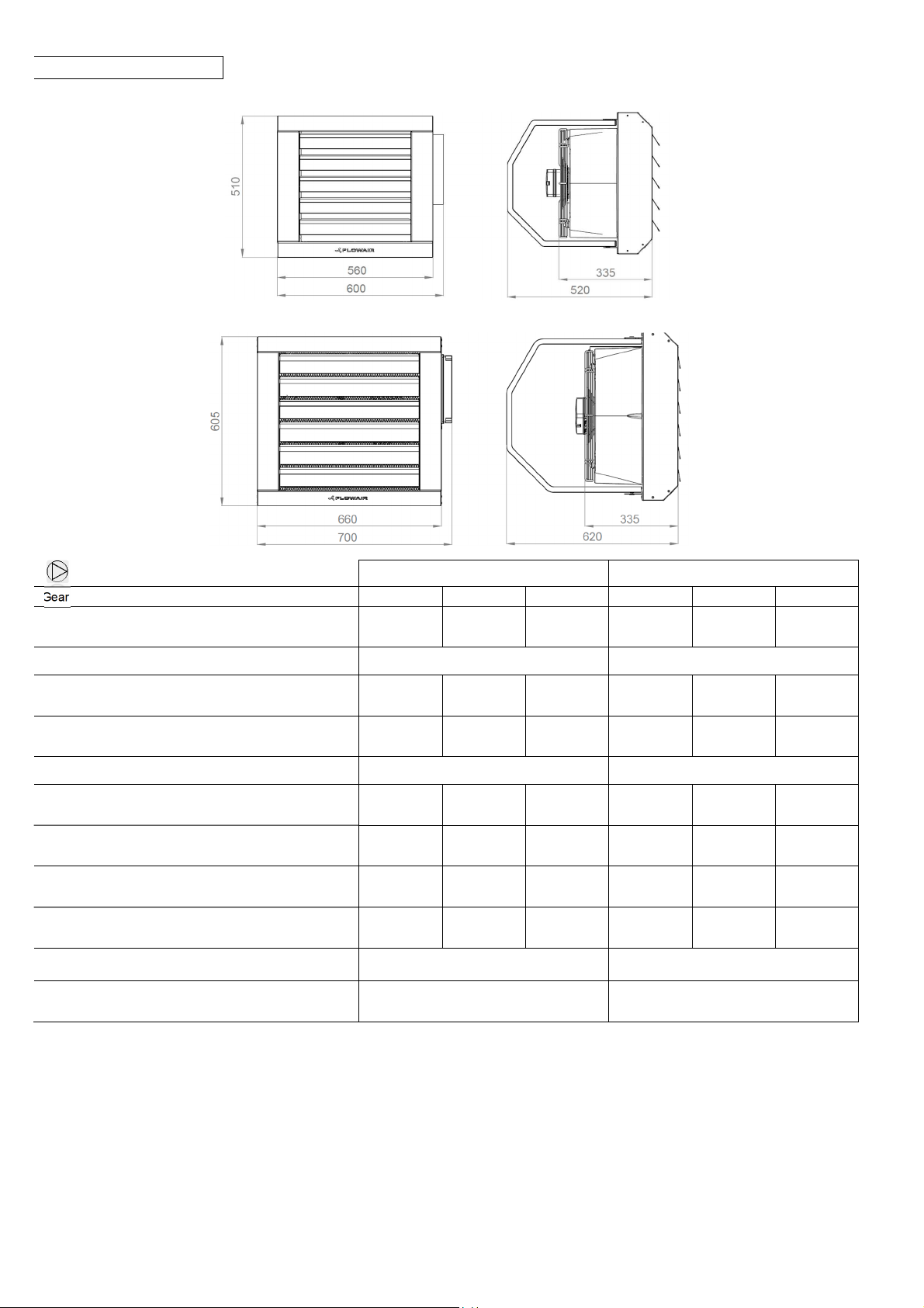
2. TECHNICAL DATA
EL S BMS
EL L BMS
LEO EL S BMS LEO EL L BMS
Gear |
III
II
I
III
II
I
Max airflow [m
3
/h ] |
2000 1600 1250 4250 2800 1700
Power supply [V/Hz]
3x400/50 3x400/50
Max current Fan consumption [A]
0,6 0,4 0,3
1,4 1,2 0,6
Max Fan power consumption [W]
130 90 70
330 240 120
Fan IP/ Insulation class
54 /F 54 /F
Acoustic power level [dB(A)]*
71,4 65,8 59,0 79,2 69,6 57,2
Acoustic pressure level [dB(A)]**
56,3 50,7 43,9 64,1 54,5 42,1
Horizontal range***[m]
14,0 11,0 8,5
24,0 15,0 9,5
Vertical range**** [m]
5,3 4,3 3,4
8,3 5,5 3,5
Device mass [kg]
19,7 27,8
50 50
Max working temperature [
o
C]
* Acoustic power level according to EN ISO 3744:2011
**Acoustic pressure level has been measured 5m from the unit in a 1500m
3
space with a medium sound absorption coefficient
**** Vertical nonisothermal range for ΔT = 5oC and for 0.5 m/s border air stream speed |
***Horizontal isothermal range for 0,5 m/s border air stream speed

4 |
LEO EL S BMS
Tp1 V PT PC Tp2
[°C] [m
3
/h] [kW]* [A]* [°C]
1st step of heating
0
1250/1600/2000
5,5/5,9/6,0 7,9/8,5/8,6 15/10/9
10 5,4/5,7/5,9 7,8/8,2/8,4 22/19/17
20 5,3/5,6/5,8 7,7/8,0/8,3 30/28/26
2nd step of heating
0
1250/1600/2000
9,5/10,2/10,8 13,6//14,7/15,6 28/25/19
10 9,2/9,8/10,3 13,2/14,0/14,8 32/29/24
20 8,9/9,6/10 12,8/13,8/14,4 38/34/30
LEO EL L BMS
Tp1 V PT PC Tp2
0
1700/2800/4250
7,5/8,1/8,8 10,6/11,6/12,5 11/8/6
10 7,1/7,8/8,3 10,1/11,1/11,9 20/17/15
20 6,8/7,6/8,0 9,8/10,8/11,4 29/26/24
1700/2800/4250
13,7/15,1/16,3 19,3/21,4/23,3 24/19/14
10 13,0/14,2/15,4 18,6/20,5/22,2 27/24/21
20 12,4/13,7/14,7 17,8/19,9/21,2 33/30/28
3rd step of heating
0
1700/2800/4250
18,0/20,3/22,8 26,0/29,2/33,3 29/24/18
10 17,2/19,6/21,2 24,5/28,0/31,0 36/30/26
20 16,6/19,1/20,6 24,0/27,5/30,1 44/38/34
2. TECHNICAL DATA
V – air flow
PT – heating capacity
PC – current consumption
Tp1 – inlet air temperature
Tp2 – outlet air temperature
* including Fan parameters
2nd step of heating
0
[°C] [m
3
/h] [kW]* [A]* [°C]
1st step of heating (only with T-box)
| 5
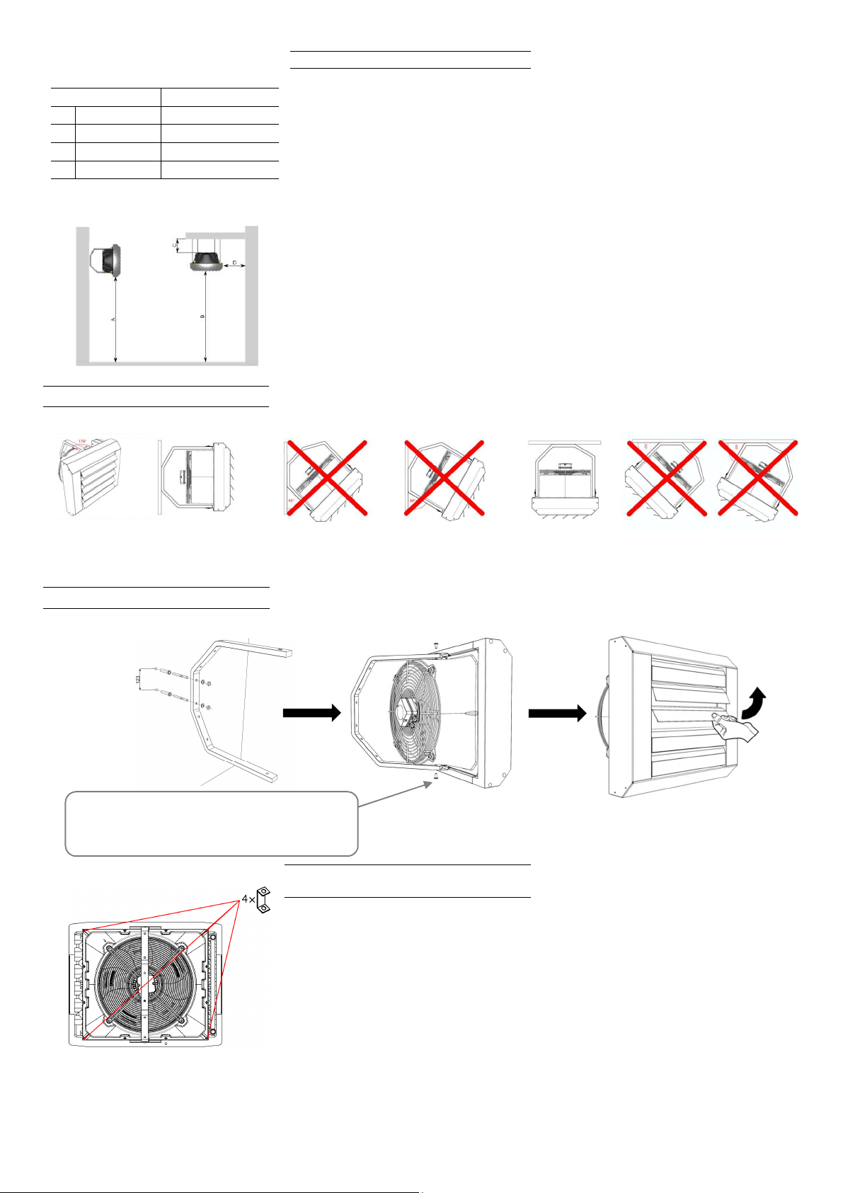
1.
EL S BMS EL L BMS
A max 3,0 max 6,0
B max. 6,0 max 9.5
C min. 0,2 min. 0,2
D min. 0,5 min. 0,5
3
. INSTALLATION
1. Fan heaters can be mounted to vertical or
horizontal partitions. During the montage, the
minimal distances from the walls and ceiling
have to be kept.
2. U-profiles should be mounted in corners as
drawing shows. Is not allowed to screw profiles
in other places.
2.
3.3 U-PROFILES (optional)
U-profiles should be mounted in corners as drawing shows. Is
not allowed to screw profiles in other places.
3.1. INSTALLATION – BRACKET
3.2. ASSEMBLY INSTRUCTIONS
!!!
M8 screws are in set with bracket
6 |
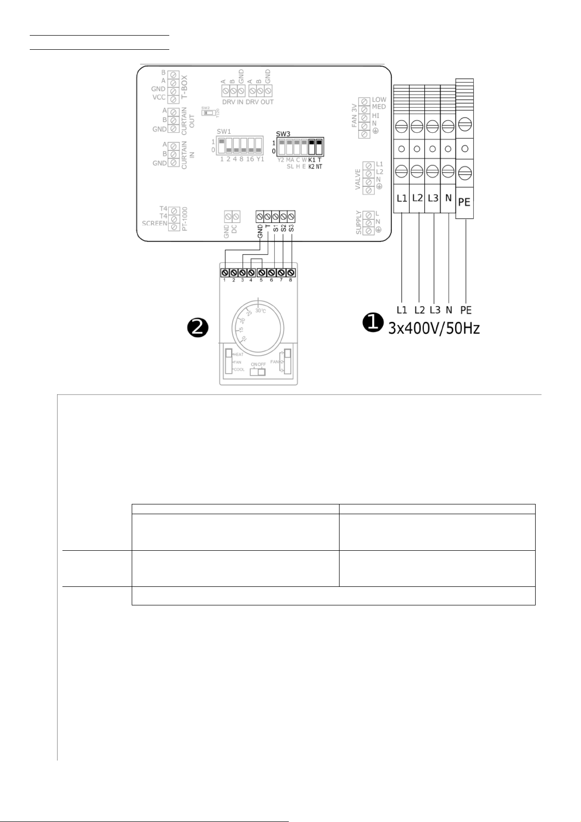
4. CONNECTION DIAGRAMS
V
3- step fan speed regulator with thermostat TS (OMY 5x0,5 mm
2
).
LEO EL S
LEO EL L
•1
1
st
step of heating; 2
nd
fan step
2
nd
step of heating; 2
nd
fan step
•2
2
nd
step of heating; 3
nd
fan step
3
rd
step of heating; 3
rd
fan step
•3 Ventilation (fan operate on 3
rd
step)
SW3:
T- Thermostatic mode (After reaching the temperature, turning off the fans and heating elements)|
NT - Continuous mode (After reaching the temperature, turning off the heating elements and continuous operation of the fan)|
K1 – LEO EL L BMS
K2 – LEO EL S BMS
Each time the device is switched off the heaters are being cooled for next 30 seconds
Power supply
•LEO EL S BMS (OMY 5x4,0 mm
2
) (Circuit protection B20)
•LEO EL L BMS (OMY 5x6,0 mm
2
) (Circuit protection B40)
•HEAT- heating mode
•FAN - room thermostat deactivated
•COOL - cooling mode
| 7
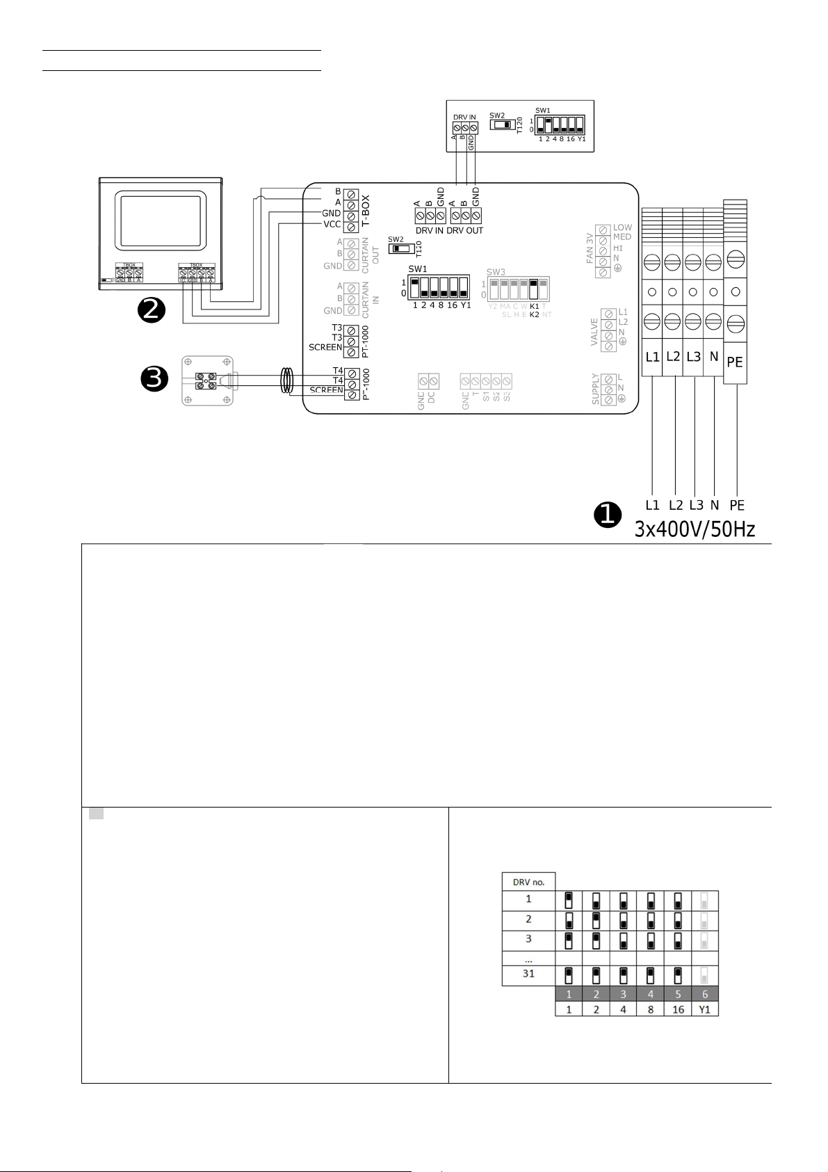
4. CONNECTION DIAGRAMS
B
M
S
T-box - intelligent controller with touch screen
PT-1000 connectors
SW3:
K1 – LEO EL L BMS
K2 – LEO EL S BMS
Each time the device is switched off the heaters are being cooled for next 30 seconds
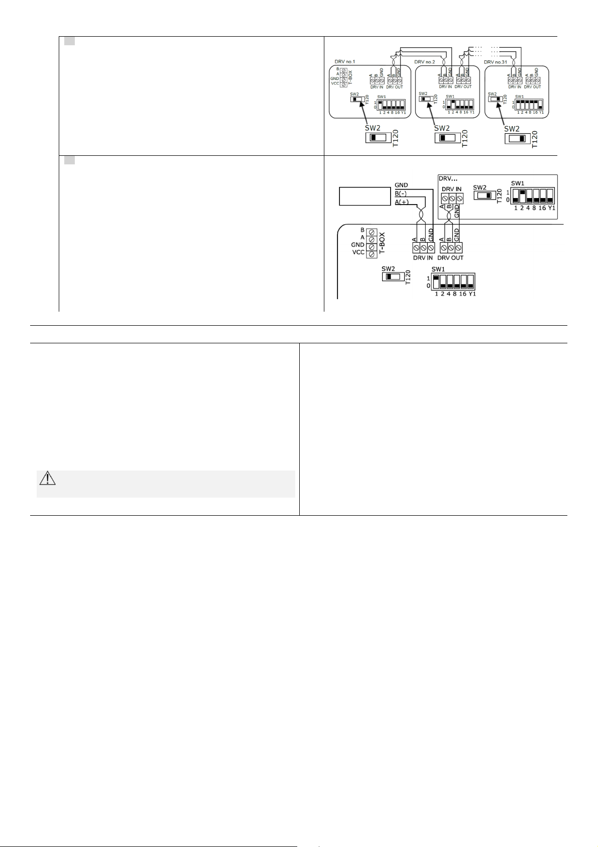
EN
:
When connecting DRV modules to the T
-
box controller or BMS, you
have to binary set addresses on each (each DRV must have individual
address) DRV module by DIP-switch SW1. To address modules check if
the power supply is turned off, than set then the addresses as shown in the
table, than turn on the power supply .
.
)
•LEO EL L BMS (OMY 5x6,0 mm
2
) (Circuit protection B40)
Power supply 3 x 400V/50Hz:
•LEO EL S BMS (OMY 5x4,0 mm
2
) (Circuit protection B20)
8 |
EN
:
It is possible to connect up to 31modules
DRV and control them with
one T-box controller .|
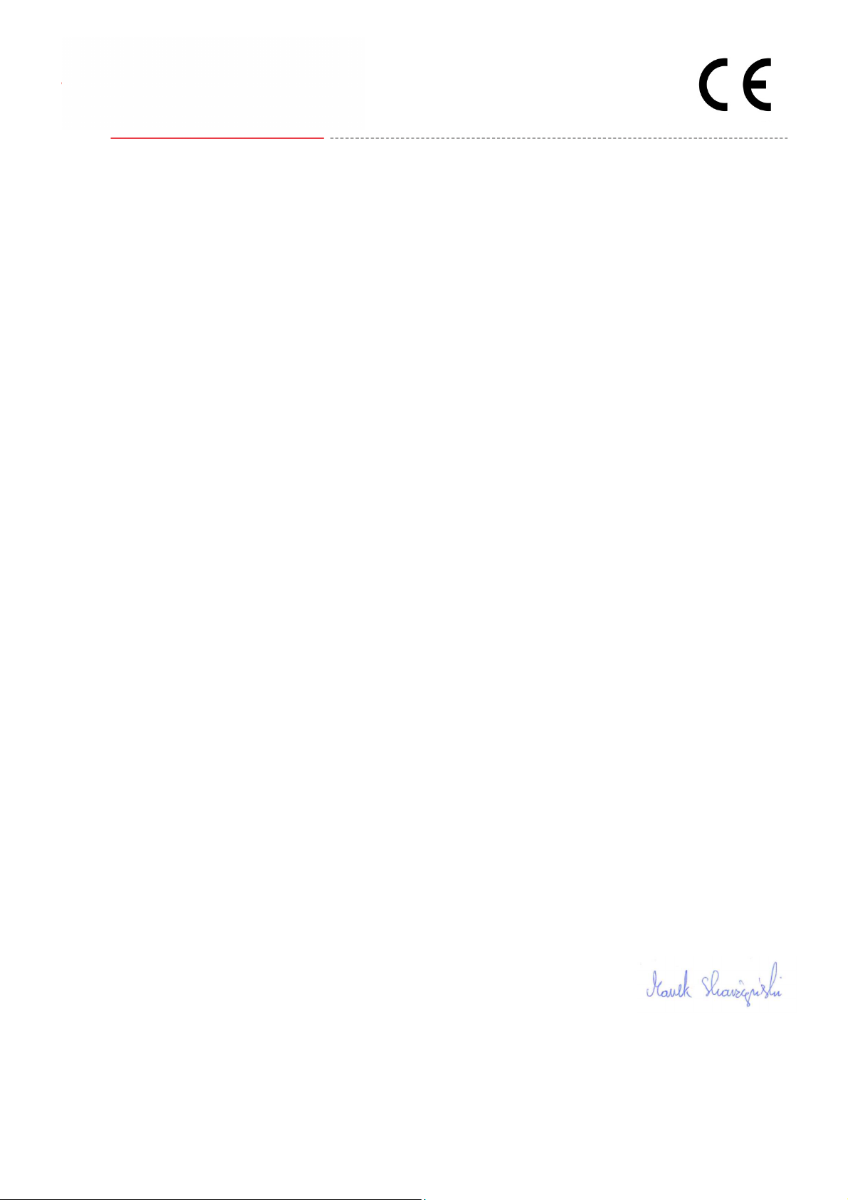
EN
:
DRV modules can be connected to the BMS (Building Management
System).
5
.
START
-
UP AND OPERATION
Start-up
•supply and controls have to be connected as shown in technical manual
•before connecting supply check that current is same as on the nameplate
•start-up without grounding cable is forbidden
Operation
•unit designed to indoor operation
•never place any things on the casing while operating
•unit should be serviced periodically; in case of failure the unit should be
switched off immediately
Never operate a failure unit. The producer does not take any
responsibility for damages caused by failure operation.
Switch off the electrical supply while servicing or cleaning.
Periodic inspections
To keep proper technical parameters Flowair recommends periodic
service (every 6 months) of fan heaters on behalf of the user.
During inspections user should:
Check heating elments , if is it filled with dirt or dust. If necessary - use
industrial vacuum cleaner or pressurized air stream to clean the
exchanger’s lamellas.
Excessive dirt on the heaters can cause
permanent loss of the rated parameters,
Check fan blades, in case of dirt use damp cloth and remove dirt,
Check bracket installation,
Check wires insulation,
Check power supply,
Check levelling of the unit.

| 9

10 |
6. SERVICE AND WARRANTY TERMS
Please contact your dealer in order to get acquitted with the
warranty terms and its limitation.
In the case of any irregularities in the device operation, please
contact the manufacturer’s service department.
The manufacturer bears no responsibility for operating the
device in a manner inconsistent with its purpose, by persons
not authorised for this, and for damage resulting from this!

| 11

12 |
7. CONFORMITY WITH WEEE DIRECTIVE 2012/19/UE
For information on the collection system of waste electrical
and electronic equipment, please contact the distributor.
R E M E M B E R :
Do not dispose of used equipment together with other waste! There
are financial penalties for this. Proper handling of used equipment
prevents potential negative consequences for the environment and
human health. At the same time, we save the Earth's natural
resources, reusing resources obtained from the processing of
equipment.
Running a business without harming the environment and
observing the rules of proper handling of waste electrical and
electronic equipment is a priority for Flexiheat.
The symbol of the crossed out wheeled bin placed on the
equipment, packaging or documents attached means that the
product must not be disposed of with other wastes. It is the
responsibility of the user to hand the used equipment to a
designated collection point for proper processing. The symbol
means at the same time that the equipment was placed on the
market after August 13, 2005.

| 13
14 |
ww
•LEO EL L BMS; LEO EL S BMS
PN-EN ISO 12100:2012
Safety Of Machinery - General Principles For Design - Risk Assessment And Risk Reduction
PN-EN 60204-1:2018-12
Safety of machinery − Electrical equipment of machines − Part 1: General requirements
environments
Gdynia, 14.01.2019
Product Manager
Flexiheat hereby confirms that heating unit / Flexiheat
Declaration Of Conformity /
were produced in accordance to the following Europeans Directives / zijn geproduceerd in overeenstemming met de volgende
1.
2014/30/UE – Electromagnetic Compatibility (EMC)
2. 2006/42/WE – Machinery
3.
2014/35/UE – Low Voltage Electrical Equipment (LVD)
4. 2009/125/WE – Energy-related products (ErP 2015)
and harmonized norms ,with above directives
PN-EN 60034-1:2011 Rotating electrical machines — Part 1: Rating and performance
PN-EN 61000-6-2:2008 Electromagnetic compatibility (EMC). Generic standards. Immunity for industrial

om
| 15
COMMISSION REGULATION (EU) 2016/2281
Capacity control: 3-speed
LEO EL S LEO EL L
Item Symbol Value Unit
Rated heating capacity P
rated,h
10,8 22,8 kW
Minimum capacity P
min
5,5 7,5 kW
Envelope loss factor F
env
0 0 %
Emission efficiency η
s, flow
93,3 95,6 %
Seasonal space heating energy efficiency η
s, h
35,7 36,6 %
Information relevant for disassembly, recycling and/or disposal at end-of-life.
isassembly should be carried out by a person with appropriate authorizations. After disassembly,
waste should be segregated:
housing: steel - recyclable
heating elments: aluminum,
fan: dispose of in accordance with the rules for the disposal of electrical equipment
Unit name: LEO EL

16 |
www.flowair.com
52383
MT-DTR-LEO-EL-S-L-EN-PL-NL-RU-V1
This manual suits for next models
1
Table of contents
Other Flexiheat Heater manuals


Popular Heater manuals by other brands

Bionaire
Bionaire BOH1503 instruction manual

Herschel
Herschel Inspire Comfort IC-400 Installation & operating instructions

Gabarron
Gabarron CP Series Installation instructions and user guide

WMT
WMT Y-Panel User information

Henley Stoves
Henley Stoves Athens 400 Installation & operating instructions

Euromate
Euromate 107446 Original instructions

L.B. White
L.B. White CP350AK owner's manual

DELTACALOR
DELTACALOR DROP Operation and installation manual

Bio Green
Bio Green Phoenix 2.8 Installation and operating instruction

TESY
TESY MC 20111 Operation and storage manual

Pro-Elec
Pro-Elec PELL0206 manual

Frico
Frico ICW Series Assembly and operation instructions


