FLI UNDERGROUND FU10A Parts list manual

UNDERGROUND
INSTRUCTION &
INSTALLATION MANUAL
MODEL: FU10A, FU12A, FU12TA
active
enclosure

INTRODUCTION
This instruction manual is for your safety and must be adhered to at all times. Please read and
ensure that you fully understand the installation and set up procedures as explained. If you are
unclear on the installation or set up of your FLI UNDERGROUND subwoofer enclosure please
contact your nearest authorised FLI UNDERGROUND dealer.
Thank you for purchasing this FLI UNDERGROUND subwoofer enclosure. It will
provide you with years of trouble free usage providing you follow a few simple
guidelines.
2
WARNING
DO NOT EXPOSE THIS PRODUCT TO DAMP OR MOISTURE - doing so may result in fire,
shock or damage to the product.
BEFORE WIRING DISCONNECT THE CABLE FROM THE POSITIVE BATTERY TERMINAL
- failure to do so may result in electric shock or injury.
ENSURE GOOD AND CORRECT CONNECTIONS - failure to make the correct connections
may result in fire or damage to the product.
KEEP THE VOLUME AT A LEVEL SO YOU CAN STILL HEAR OUTSIDE NOISE - failure to do
this may result in an accident. FLI UNDERGROUND equipment is capable of producing sound
levels that can permanently damage your hearing. FLI UNDERGROUND recommends caution
when listening at high volume. For safe and enjoyable listening the sound should be comfortable
and clear without distortion.
CAUTION
• Never connect any speaker lead to the car chassis. This can cause severe damage to your
speaker / car radio / amplifier.
• Before drilling or cutting any holes, investigate the layout of your vehicle thoroughly.
• Use caution when working near the fuel / hydraulic lines and electrical wiring.
• Observe the correct polarity when wiring, improper phasing may cause a loss of bass
response.
• Ensure that no moving parts catch on the speaker or grill (e.g. window or door handles, or
window glass inside the door)
INSTALLATION
• The quality of the installation will affect the system performance and reliability.
• Contact your nearest authorised FLI dealer if you are unsure about the installation of this
product.
• Please mount this unit away from any potential hazards.
• Minimising the length of wires will provide higher audio output from the system.
• The speaker should be securely fastened to the mounting position using the screws
provided.
• Pre drill your mounting holes using a drill and position with the template provided.
• Be sure to investigate your mounting area thoroughly for electrical wires, brake or fuel lines or
fuel tank to prevent causing any damage.
BLE F
ock or injur
ONNECTIONS
-
roduct.
L SO YOU CAN STILL HE
LI UNDERGROUND equipme
amage your hearing. FLI UNDER
e. For safe and enjoyable listening th
speaker lead to the car chassis. This can cause
o / amplifi
cutting any holes, investigate the layout of your vehicle
hen working near the fuel / hydraulic lines and electrical wirin
correct polarity when wiring, improper phasing may cause
at no moving parts catch on the speaker or grill (e.g. window or do
glass ins
TALLA
e quality
ontact your nearest authorised FLI dealer if you are unsure about the installation o
product.
Please mount this unit away from any potential hazards.
the system
aler if
RGROUND
r hearing.
d enjoyabl
car chas
tigate th
/ hydrau
ing, im

3
Run in procedure
FLI recommends that you follow the run in procedure for the subwoofer detailed
below.
When your subwoofer is used for the first time naturally like most brand new items it is very
stiff and rigid, it will take time for the moving parts of this subwoofer to loosen up before it
will be ready to deliver its full potential.
For the first 30 hours it is recommended that you play the subwoofer initially at low to medium
volumes, gradually increasing the volume level as time progresses. As a guide, if you listen to it for
1 hour every day it will take a month for the speaker to run in properly. You will notice a big change
in the sound of the subwoofer over this period, as the spider and surround begin to run in the sound
will get deeper and punchier, also the output of it will increase as the suspension loosens up.
A new subwoofer is like a new car engine, it needs a few thousand miles before you can drive it to its full
potential, driving it into the ‘red line’ from the first day will mean engine damage is certain and will not be
covered by warranty and the same applies to the subwoofer. Failure to follow this simple procedure is the
most common reason for a subwoofer to fail after a very short period of time.
Installation
The most common place to mount a bass enclosure is in the luggage compartment of the vehicle. Where in
the luggage compartment it is mounted will have an effect on the sound produced allowing the user to tailor
the sound to best suit their musical tastes. For example if the enclosure is mounted facing the rear bumper,
the bass produced will be noticeably deeper than if it is fired into the rear seat.
Do not be afraid to experiment with positioning as a little time and effort can yield great improvements in
sound.

4
Active enclosure Installation
Your FLI UNDERGROUND enclosure is designed with a swift installation routine in
mind. Please mount the enclosure in a dry location on a solid surface. NEVER mount the
enclosure upside down, this will cause the amplifier to overheat and will eventually damage
the amplifier. Before fixing the enclosure in place please ensure that there is sufficient air
flow around the amplifier heatsink, at least two inches will be sufficient.
Power Cable
• At least a 10 gauge cable should be used for both the power and the ground connections to the
amplifier.
• The power cable should be taken directly from the battery. Rubber grommets should be used
when passing through any bulkheads to prevent the cable from becoming chaffed or cut.
• It is vital that a fuse / circuit breaker (of at least equal value to the one fitted on the amplifier) is placed
in line with the power cable and is no further than eighteen inches away from the battery.
• Please ensure that the fuse is not fitted until the entire installation procedure is complete.
• The two tables below are to help you decide on what cable is correct for you. The first enables you to
select the size of cable depending on the length required. The second will help you convert the cable size
from American Wire Gauge to Metric if you need to.
L
en
g
t
h
of
Run
C
urren
t
de
m
an
d
0
–
4
F
t
4
–
7
F
t
7
–
1
0
F
t
1
0
–
1
3
F
t
1
3
–
1
6
F
t
1
6
–
1
9
F
t
1
9
–
22
F
t
22
–
2
8
Ft
0
–2
0
amp
s
14
1
2
1
2
1
0
1
0
8
8
8
20–
3
5
amp
s
1
2
1
0
8
8
6
6
6
4
35
–
50
am
p
s
1
0
8
8
6
4 4 4 4
50
–
65
am
p
s
8
8
6
4
4
4
4
2
65
–
85
amp
s
6
6
4
4
2
2
2
0
85
–1
05
amp
s
6
6
4
2
2
2
2
0
105–12
5
amp
s
4
4
4
2
0
0
0
0
125
–
150
a
mp
s
2
2
2
0
0
0
0
0
A
WG
AA
t
o
Me
tri
c
C
onversio
n
C
har
t
cross
sec
ti
o
n
al
area
A
WG
AA
Nu
m
be
r
I
n
c
h
m
m
m
m
2
0
0
.
3
2
5
8
.2
5
53
.
5
1
0
.2
89
7.
35
42.4
2
0
.
2
5
8
6
.5
4
33
.
6
3
0
.22
9
5
.8
3
26.
7
4
0
.2
0
4
5
.1
9
21.
1
5
0
.
182
4.
62
16
.
8
6
0
.16
2
4.
1
1
1
3
.
3
7
0
.144
3
.
66
1
0
.
5
8
0
.12
8
3
.2
6
8
.
36
9
0
.
1
14
2.9
1
6.6
3
1
0
0
.1
02
2.
59
5
.2
6
1Metre–
3
.2
8
Fe
e
t

5
ground cable
• The ground cable needs to carry the same current as the power cable. At least a 10
gauge cable should be used.
• The amplifier ground should be connected directly to the chassis of the vehicle, to bare
metal.
• The cable length should be kept to an absolute minimum. It is not recommended that you
connect the ground cable to the vehicle’s seatbelt anchor point.
Remote Turn On
• A minimum of 18 gauge cable should be used for this connection.
• The cable should be run with exactly the same care and attention as the power cable and taken
back to the source (headunit) and joined to the remote cable provided.
• If the source (headunit) does not have a remote turn on cable then a 12v supply should be used. This
will require a switch to be fitted inline to enable the amplifier to be turned on and off. Remember that
if this switch is left on you will flatten the car battery.
RCA Cables
• Please take extra care when running these cables from the source to the amplifier. Ensure that they are
placed away from all items that can generate any interference, wiring harnesses etc.
• It is recommended that the RCA cables should be run on the opposite site of the car to any previously
installed power cables, if possible.

6
AMPLIFIER CONNECTIONS & CONTROLS
A. LOW LEVEL INPUT
Low level input for connection to any source (headunit) with a low level output. This is your RCA output from
the source (headunit).
B. HIGH LEVEL INPUT
To be used when no RCA’s are available. Use the provided loom to connect to the closest speakers.
C. GAIN CONTROL
Used to match the input signal of the source (headunit) to the amplifier. See the setup section for more details.
D. CROSS OVER FREQUENCY CONTROL
High pass frequency control. The frequency ranges from 50hz to 250 Hz.
E. BASS BOOST CONTROL
To provide up to an extra +6 dB of bass boost at 45 Hz. Use this boost to increase bass output from the
amplifier.
F. FUSE
Please ensure the following fuse rating is used when replacing fuses:
FLI UNDERGROUND FU10A, FU12A (20 amp)
FLI UNDERGROUND FU12TA (25 amp)
G. POWER CONNECTIONS
Power connections. See Connections section for details on correct connections.
H. POWER PROTECT LIGHT
When the amplifier is operating correctly the light will illuminate constant ‘green’. When the amplifier is in
power protecttion mode the light will illuminate ‘red’.
A
EB
CF D
G H

7
Set Up Section
To correctly set the gain control of the amplifier to match that of the source (headunit)
use the following setup routine:
• Turn the gain control to minimum on the amplifier.
• Ensure the bass boost is set to 0 dB.
• On the headunit set all crossovers to flat and both bass and treble to zero.
• Turn up the source (headunit) to approx 3/4 volume.
• Very slowly turn up the gain on the amplifier until distortion can be heard in any of the speakers
or until the volume reaches an uncomfortable listening level when this is reached turn down the
gain control slightly.
• The gain control is now set.
The setting of the crossover will directly effect the sound you will hear from the subwoofer. At its
lowest setting (50 Hz) the subwoofer will only react to frequencies from around 35 Hz to 50 Hz. At its
highest setting (250 Hz) the subwoofer will react to a larger range of frequencies from around 35 Hz to
250 Hz. Experiment with this setting to achieve a sound you are happy with that feels comfortable with
the music that you listen to.

8
System Wiring
Input connections
BATTERY
FUSE
Connect to
chassis / ground
of vehicle
Connect to remote turn-on
lead of source unit
SOURCE (HEAD UNIT)

9
Troubleshooting
Before removing the amplifier, refer to the list below and follow the suggested
procedure. Always test the speakers and confirm that they are wired correctly first. If
in any doubt get help from a qualified auto electrician.
AMPLIFIER WILL NOT POWER UP
• Check for good ground connections. Ensure that the ground cable is connected directly to
bare metal and not a painted surface.
• Using a multimeter check the that remote terminal has at least 7V DC.
• Using a multimeter check that there is battery voltage on the positive terminal.
• Check all fuses.
• Check that the protection light is not illuminated. If it is lit, shut off the amplifier for thirty seconds
and then turn it back on.
PROTECTION LED ILLUMINATES WHEN AMPLIFIER IS POWERED UP
• The amplifier is designed to shut down automatically when the units temperature goes above 80
degrees. If the amplifier feels very hot then this may be the reason for the amplifier not starting.
• Check that there is good airflow around the amplifier. In some applications an external fan may be
required.
BLOWN FUSE(S)
• Check both positive supply and ground for shorts.
• Check that the positive wire is connected to the positive terminal on the amplifier.
• Check that the negative wire is connected to the ground terminal on the amplifier.
• Ensure that the correct rated fuse is fitted:
FLI UNDERGROUND FU10A, FU12A (20 amp)
FLI UNDERGROUND FU12TA (25 amp)
DISTORTED SOUND
• Check the gain control is not set at too high a level. If the sound is distorted turn the down the gain until the
sound is clear.
• Check that all crossover frequencies are correct. See Setup section for more details.
• Check that the ground cable is making good contact with the vehicle chassis.
• Check the the RCA cables are making good connection with the source and amplifier.

10
specifications
KEEP IT SAFE
Staple your receipt here:
MODEL NUMBER:
SERIAL NUMBER:
PURCHASED FROM:
DATE OF PURCHASE:
In order to protect your purchase and aid your warranty please fill
in the following form and keep it safe for your future reference.
For more information and to register your warranty online, visit:
www.fliaudio.com/warranty
Model
Driver
Amplifier
RMS power
Peak power
Impedance
Height
Depth
Width
FU12TA
FU12 x 2
FU300.1
600 watts
2000 watts
4Ω
13.7” (347mm)
15.9” (405mm)
28.3” (720mm)
FU10A
FU10
FU150.1
250 watts
800 watts
4Ω
FU12A
FU12
FU150.1
300 watts
1000 watts
4Ω
12.5” (317mm)
14.5” (369mm)
12.2” (310mm)
13.7” (347mm)
15.9” (405mm)
14.2” (360mm)

LIMITED WARRANTY
All FLI goods are covered by a full 12 months manufacturers warranty. Valid
from the date of the original receipt and proof of purchase. In order to validate
this warranty, the warranty card should be returned to FLI within seven days
of the original purchase date. The original receipt and packaging should also
be kept for this 12 month period.
If at any stage during the warranty period you have a problem with the product
then it should be returned to the point of purchase in its original packaging,
complete and with no items missing. If the store is unable to fix the product it
may have to be returned to FLI this process takes around 7 working days.
A full description of FLI’s warranty information can be found on our website:
www.fliaudio.co.uk/warranty
A written version can also be obtained from:
FLI warranty department
PO Box 11000
B75 7WG
UK
COPYRIGHT
All content included in this manual such as text, graphics, logos, icons, images data, the selection
and arrangement thereof, are the property of FLI Audio (herein referred to as “FLI”, “us” or “we”)
and its affiliate or their content and technology providers, and are protected by United Kingdom
and International copyright laws. All rights reserved.
TRADEMARKS
FLI UNDERGROUND™, FU™, UNDERGROUND™ and all stylised representations of product
names, or the abbreviations of product names, as logos are all trademarks of FLI. Graphics and
logos are trademarks or trade dress of FLI Audio or its subsidiaries. FLI’s trademarks and trade
dress may not be used in connection with any product or service that is not FLI’s, in any manner
that is likely to cause confusion among customers or in any manner that disparages or discredits
FLI. All other trademarks not owned by FLI or its subsidiaries that appear in this manual are the
property of their respective owners, who may or may not be affiliated with, connected to, or
sponsored by FLI or its subsidiaries.
We reserve the right to make needed changes or improvements to the product
and this manual, without informing the customer about this in advance.
11
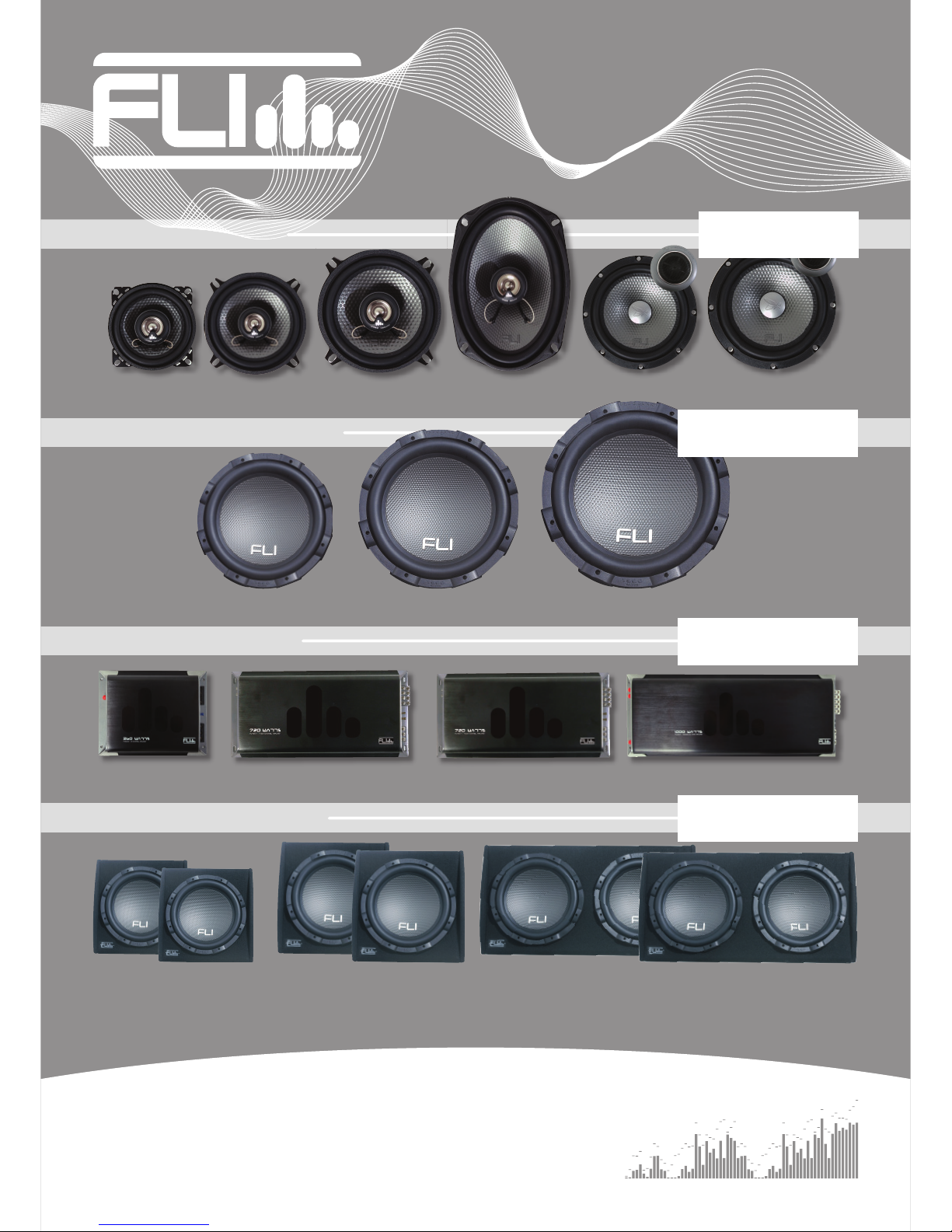
AVAILABLE NOW IN THE
FLI UNDERGROUND RANGE:
UNDERGROUND
www.fliaudio.com
up to
up to
270 watts
270 watts
speakers
FU 4 FU 5 FU 6 FU 69 FU 5c FU 6c
FU 10 FU 12 FU 15
FU 360 FU 720 FU 1000.1 FU 1000.5
FU 10P
FU 10A
FU 12P
FU 12A
FU 12TP
FU 12TA
up to
up to
1200 watts
1200 watts
up to
up to
1000 watts
1000 watts
up to
up to
2000 watts
2000 watts
subwoofers
AMPLIFIERS
ENCLOSURES
This manual suits for next models
2
Table of contents
Other FLI Enclosure manuals


Popular Enclosure manuals by other brands

Crest Audio
Crest Audio Versarray Pro 218 Product specifications

OWC
OWC Value Line Assembly guide

Thermaltake
Thermaltake GTS VO3000 Series user manual

Siemens
Siemens SIRIUS ACT 3SU180-N Series Original operating instructions

AirClean systems
AirClean systems POWDERSAFE 760C Operator's manual

2E
2E GAMING VERTEX BLACK Operation guide

Safe-t-Cover
Safe-t-Cover 200D Series Assembly instructions

Philips
Philips SL300I/05 Instructions for use

IBM
IBM TotalStorage EXP100 Installation, user's, and maintenance guide

DirecTV
DirecTV D2 Advantage Lite Installation and troubleshooting guidelines

HighPoint
HighPoint RocketStor 6414AS Setup guide

Belkin
Belkin F5U209 user manual


