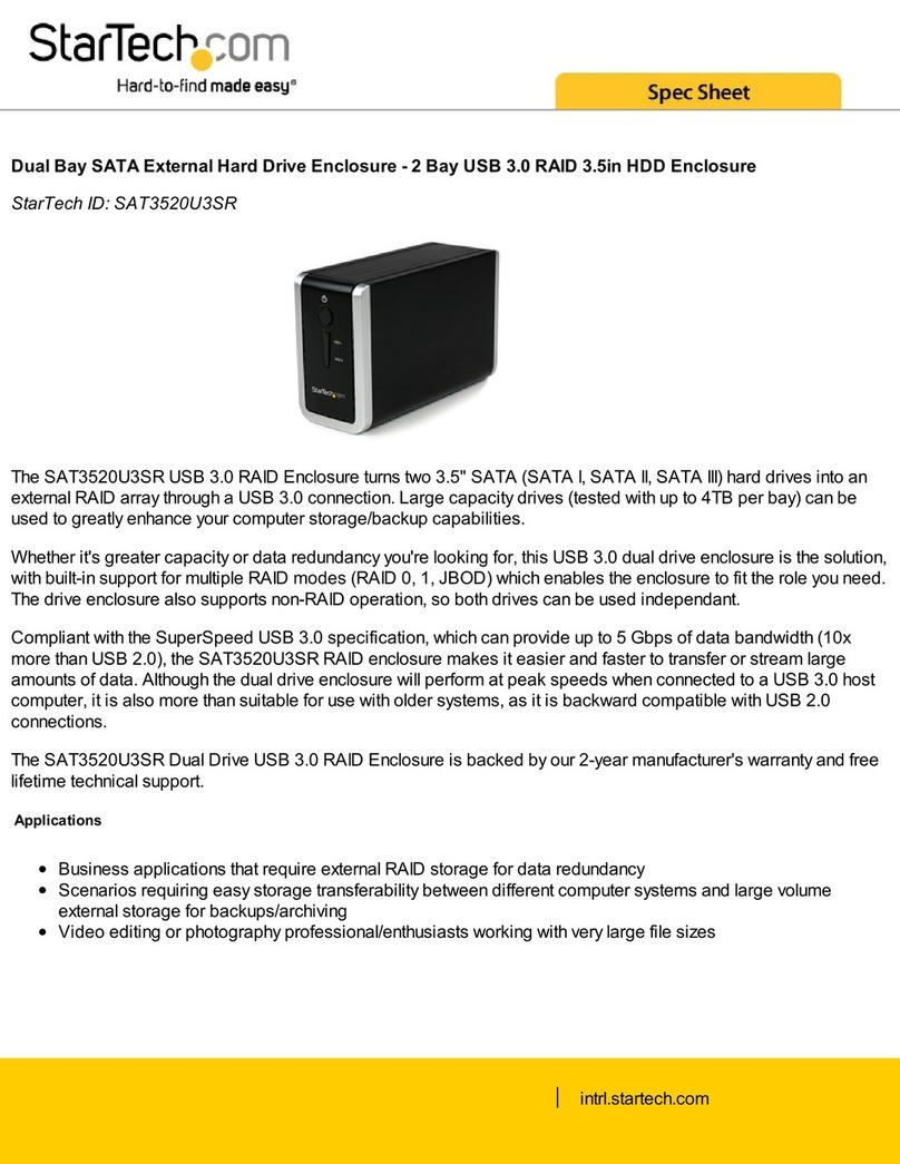
Flight Display Systems FD800JBOX VER RJ45 User manual

MAN – FD800JBOX VER RJ45
Installation and Operation Manual
FD800JBOX VER RJ45
Technical Support
470-239-7421
www.FlightDisplay.com
Revision Date: September 29, 2014
Rev: F
JetJukebox
SMART CONNECTIVITY

MAN – FD800JBOX VER RJ45
FD800JBOX VER RJ45
Audio/Video JukeBox
Flight Display Systems
6435 Shiloh road, Suite D
Alpharetta, GA 30004
Phone: 678-990-6682
Fax: 678-792-8681
Sales@FlightDisplay.com
www.FlightDisplay.com
For the most current copy of all product manuals, please visit our website at:
www.FlightDisplay.com
© 2014 Flight Display Systems. All Rights Reserved.
Reproducing copyrighted materials is in violation of the law and could subject
users to substantial fines as well as civil or criminal liability, it is recommended
that you contact your legal advisor or the music or movie label if you are at all
uncertain about your rights.

MAN – FD800JBOX VER RJ45
Contents
General Information 5
New Capabilities 5
Additional Information 5
Specifications 6
Installation Instructions 7
Power 7
Wiring Suggestions 7
Power and Ground Wiring 7
Front View with Connectors 9
J1 – Power/Data 10
J2 - HDMI 11
J3 - VGA Video, J4 & J5 - Ethernet Connectors 12
Operation Instructions 13
Connecting to the Test Wi-Fi Router 13
Connecting to the Default Wireless Network 13
Connecting to JetJukebox using an iPad 14
Home Screen Icon Definitions 14
Playing Internal Media 15
Movies 15
Photos 17
Music 19
Browse 21
External Media and Camera 22
Bulkhead Functionality 23
Bulkhead Media Home Screen 24
Moving Map 26
Loading New Content 28
File Types 28
iPad®/iPhone®and Streaming DRM Files from iTunes 28
Copying Files to the Internal Solid State Disk 29
USB Copy 29
Network Copy 30

MAN – FD800JBOX VER RJ45
Creating MP4 Files 31
Moving Map Features and Configuration 33
Abbreviations 33
Features and Pages 33
Advanced Configuration and Troubleshooting 33
ARINC-429 Data Capture 34
USING RS-232 DATA 36
RS-232 Data Capture 36
Technical Drawing 38
Troubleshooting 39
Video Noise 39
Snow or Sweeping Lines 39
Technical Support 39
Instructions for Continued Airworthiness 39
Warranty Information 39
Change Log 40

MAN – FD800JBOX VER RJ45
General Information
The FD800JBOX VER RJ45 is a combination wireless
media storage device and moving map computer. The
unit allows up to eight users to simultaneously stream
content to a carry-on personal electronics device – such
as iPads®, iPhones®, smart phones, laptop computers
and tablets. Using a friendly web browser interface such
as Google Chrome or Safari. Content can be streamed
from the internal 1TB solid-state drive or external USB
thumb drives. The moving map as well as the video
content can be displayed on the user’s carry-on personal
device. The moving map can also be displayed on a
bulkhead monitor by hard wiring the HDMI or VGA video
output.
New Capabilities
The FD800JBOX VER RJ45 has been enhanced with new
capabilities. JetJukebox now has the ability to interface
with the Smart Cabin CMS to control many cabin
functions. This includes cabin lights, video, audio, and
more. Video can now be streamed to a bulkhead monitor
as well as the personal electronic devices. In addition, the
Moving Map resolution has been increased fivefold. The
standard resolution has been 500 square meters per pixel.
The new resolution is 90 meters per pixel. Storage space
was also increased to one terabyte from 240GB. The new
solid state drive can store over 400 movies, television
programs, corporate or home videos.
Additional Information
The FD800JBOX VER RJ45 can be connected to a
low power, test Wi-Fi router or a permanently installed,
certified Wi-Fi product sold by Aircell®, True North®and
other manufacturers. Users simply connect to the Wi-Fi,
type in the web address of the JetJukebox, and are then
ready to access the movies and map wirelessly from their
own devices. The FD800JBOX VER RJ45 has (2) forward
facing USB ports and (4) rear facing USB ports. These
can be used to playback content stored directly on a
thumb drive or USB hard drive. The USB ports can also
be used to load additional content onto the internal 1TB
solid-state drive. In addition to plugging in USB thumb
drives and playing back personal videos, passengers can
also plug in a USB camera and view the pictures on the
personal electronics device.
Revision:
Revision Date:
Page:
F
5
September 29, 2014

MAN – FD800JBOX VER RJ45
Specifications
Dimensions 6.35”(W) x 1.95” (H) x 9.75”(D)
Weight 3 lbs.
Power Input 28V DC @ 1.5 A Max. Cont. Steady-State
Power Output 5V DC @ 1 Max. to Power Test Wi-Fi Router
File Types Video: MP4 Part 10/H.264 Files
Audio: MP3
Pictures: JPG, PNG, BMP
Storage Internal: (1) Terabyte SSD
External: USB Thumb Drives, USB Hard Drives
FMS/GPS Data Interface ARINC 429, RS-232
Video Outputs VGA, HDMI
USB 2.0 Interface (2) x Front Facing, (4) Rear Facing
RJ45 Network Interface (2) x 10/100/1000 Mbps
Operating Temperature 0-50° C (32-122° F)
Test Certifications DO-160 Section 21, Category B
Inrush Current Measurement 17 Amp for 2uS,
7 Amp for 1uS,
1.5A for 12mS

MAN – FD800JBOX VER RJ45
Revision:
Revision Date:
Page:
F
7
September 29, 2014
MAN – FD800JBOX VER RJ45
Installation Instructions
All cabin equipment, such as the FD800JBOX VER RJ45,
should be installed on a non-essential bus and have a
dedicated circuit breaker.
There are (8) #10 mounting locations on the unit: (4) on
the side flange and (4) on the bottom flange. Flight Display
Systems recommends using at least (4) #10 screws on
the bottom flange or the side flange. Mounting the unit
with (2) #10 screws on each side is also an acceptable
method of mounting the unit.
The FD800JBOX VER RJ45 requires adequate airflow
to prevent overheating. The top and the side ventilation
holes must be unobstructed to allow the forced air
cooling of the system to operate. Flight Display Systems
recommends one inch of clearance to allow adequate
intake and exhaust of air.
Power
This is a 28VDC CPU that requires 1.5 Amps of maximum
continuous steady-state power to operate. The unit turns
on automatically upon power application.
There is a combination power indication light and power
switch on the front of the unit that can be used to turn off
or reset the system if required.
Wiring Suggestions
For balanced signals on twisted pair cable, all shields
should be grounded to the connector at the source, and
floating at the display.
Avoid routing video wiring parallel to:
uAC wiring
uStrobe wiring
uDC motor supply cables
uInverter cabling
uOr any other potential noise source.
Power and Ground Wiring
20 AWG wire is recommended for Power and Ground
applications.
This is a 28V DC computer that requires 1.5 amps of
power to operate. To operate properly this product
requires an input voltage of 24-29VDC.
The rated current of the equipment and associated
voltage drop should be taken into consideration when
selecting wire gauge. The following example is based
on an install with a 28VDC power system and a total of
50 feet of wire between the circuit breaker, monitor and
ground.
Example: 22awg wire has 16.2 Ohms per 1000 feet, this
equates to. 81 Ohms for 50 feet. 3 Amps of current
on.81 Ohms will drop 2.43 Volts.
Resistance of Wire Type M22759/16-** (** = Gauge)
Gauge (AWG) OHMS/1000’
24 26.20
22 16.20
20 9.88
16 4.81
12 2.02
10 1.26
8 .70
Also, use short heavy gauge wire and a clean tight
connection for ground.
It is the installer’s responsibility to understand the
product’s requirements to install the product in
compliance with industry standards and safety.

MAN – FD800JBOX VER RJ45
Rear View with Connectors
1. J1 – DB25 Male 28V DC Power, ARINC 429 and RS-
232 for FMS/GPS Data, audio, and FDS CMS interface
via CAN.
2. USB 2.0 x (4)
These ports can be used for a USB mouse/keyboard,
thumb drives, point and shoot cameras, and USB hard
drives when adding additional content or configuring
the moving map system.
3. J2 – HDMI
This connector is used to output the moving map to
a bulkhead display with an HDMI input, HDMI video
converter, or an HDMI amplifier/switch. Use a plastic
cable tie and the metal bracket to secure HDMI
connectors.
4. J3 – VGA
This connector is used to output the moving map
to a bulkhead display with a VGA input, VGA video
converter, or a VGA amplifier/switch.
5. J4 – RJ45 #1
This RJ45 Connector is used to connect the
JetJukebox to the video streaming wireless solution;
the test Wi-Fi router or a permanently installed Wi-Fi
solution.
6. J5 – RJ45 #2
This RJ45 Connector is used to connect the
JetJukebox directly to a laptop to use a point to point
connection to load additional content.
Note* - The JetJukebox does not support playback of
content stored on cell phones and tablets plugged in
via USB at this time.
USB USB
J2
J1 J3
J4 J5
1
2 3 4 5 6

MAN – FD800JBOX VER RJ45MAN – FD800JBOX VER RJ45
Front View with Connectors
1. RESET
This button is a combination reset switch and power
indicator. To turn off the unit, hold the button for 3
seconds until the green indicator turns off. Press
the button again to boot the system. The ring
surrounding the center button illuminates green when
the unit is powered on to power the test Wi-Fi router.
If the button is pressed and immediately released, the
unit will go into sleep mode.
2. 5V DC OUT 5V DC Power Output
Used to power the test Wi-Fi router.
3. USB Input 1 & Input 2
These USB 2.0 ports are designed to store content
brought on the aircraft. This includes USB thumb
drives, point and shoot cameras, and USB hard
drives. Insert the drive into the unit, select the “Scan
Drive” icon on the home page, and the drive name
will appear on the JetJukebox home page. Click the
drive to play back content stored on the thumb drive.
This port can also be used for a mouse or keyboard
to configure the moving map or load additional
content on to the internal hard drive.
Note* - The JetJukebox does not support playback of
content stored on cell phones and tablets plugged in
via USB at this time.
Revision:
Revision Date:
Page:
F
9
September 29, 2014

MAN – FD800JBOX VER RJ45
J1 – Power/Data
Part Numbers for DB-25 mating connector and contacts
(manufactured by Tyco/Amp).
D-sub, 25 Contact Receptacle P/N: M24308/2-283
Contact P/N: M39029/63-368
Pin Number Description
1 28VDC Power Input
2 28VDC Ground Input
3 N/C
4 N/C
5 Audio Left
6 Audio Right
7 Audio Ground
8 CAN High
9 CAN Low
10 CAN Ground
11 N/C
12 N/C
13 N/C
14 N/C
15 N/C
16 N/C
17 RS232 #1 - RX
18 RS232 #1 - TX
19 RS232 Ground
20 RS232 #2- RX
21 RS232 #2 - TX
22 ARINC 429 #1 High
23 ARINC 429 #1 Low
24 N/C
25 N/C
13
25
8
20
12
24
7
19
11
23
6
18
3
15
10
22
5
17
2
14
9
21
4
16
1
DB25 Connector Front View

MAN – FD800JBOX VER RJ45
J2 - HDMI
HDMI (High-Definition Multimedia Interface) defines the
protocol and electrical specifications for the signaling, pin-
out, electrical, and mechanical requirements of cable and
connectors used for transmitting High-Definition content.
The Type A HDMI connector (shown below) has 19 pins
with bandwidth to support all SDTV, EDTV, and HDTV
modes. The plug’s outside dimensions are 13.9 mm wide
by 4.45 mm high. There is no audio output available on
the HDMI cable.
ECS manufactures an HDMI cable that is terminated at
the factory. It is ordered as part number 600-19786-XXX,
where XXX is the length in inches for the desired cable.
1
2
5
6
9
10
13
14
17
18
3
4
7
8
11
12
15
16
19
HDMI Connector
Pin Number Signal Description
1 TMDS Data 2+
2 TMDS Data 2 Shield
3 TMDS Data 2-
4 TMDS Data 1+
5 TMDS Data 1 Shield
6 TMDS Data 1-
7 TMDS Data 0+
8 TMDS Data 0 Shield
9 TMDS Data 0-
10 TMDS Clock+
11 TMDS Clock Shield
12 TMDS Clock-
13 CEC Control
14 Reserved N.C. on Device
15 SCL DDC Clock
16 SDA DDC Data
17 DDC/CEC Ground
18 +5 V Power Power EDID/DDC
19 Hot Plug Detect
Revision:
Revision Date:
Page:
F
11
September 29, 2014

MAN – FD800JBOX VER RJ45
J3 – VGA Video
Part Numbers for DB-15 High Density mating connector
and contacts (manufactured by Tyco/Amp).
D-sub,15 HD Contact Plug P/N: M24308/4-264
Contact P/N: M39029/58-360
Pin Number Description
1 Red Signal
2 Green Signal
3 Blue Signal
4 N/C
5 Sync Ground
6 Red Ground
7 Green Ground
8 Blue Ground
9 N/C
10 Sync Ground
11 N/C
12 DDC Data
13 Horizontal Sync
14 Vertical Sync
15 DDC Clock
J4 & J5 - Ethernet Connectors
The mating RJ45 connectors are standard Cat5e/Cat6
connectors. The connector below is recommended from
by the manufacturer TYCO/AMP.
Connector P/N: 5-569552-3
Use the TIA/EIA-568-B standard for wiring Cat5e/6
cables.
Pin Number Description
1 DA+
2 DA-
3 DB+
4 DC+
5 DC-
6 DB-
7 DD+
12345
6 7 8 9 10
11 12 13 14 15
DB15
View into male end

MAN – FD800JBOX VER RJ45
Operation Instructions
The FD800JBOX VER RJ45 is continuously on but can
be de-energized by removing power from the cabin
entertainment system, or pressing and holding the power
button on the front of the unit.
When applying 28VDC power, the JetJukebox will turn on
and takes roughly 90 seconds to boot. The moving map
will automatically start and begin displaying the welcome
pages or customer’s logo. At this time video can be
accessed and streamed using the web browser interface.
Connecting to the Test Wi-Fi Router
Flight Display Systems supplies a test Wi-Fi router that
can be used to test the system. This router is included
in the installation kit which is sold separately (PN FD-
JBINSTALL). This kit includes mating connectors, a USB
keyboard, USB memory stick, test harness, Ethernet
cable, and test Wi-Fi router. Connect both the Ethernet
and power cables to the Wi-Fi router. Connect the other
end of the Ethernet cable to J4 on the rear of the unit.
Finally, connect the threaded side of the power cable to
5V DC OUT on the front of the JetJukebox. See pictures
below for reference.
Connect power to the test router
Connecting to the Default Wireless Network
The procedure required to connect to the supplied
wireless router will vary slightly depending on the type of
PED in use. This is the same procedure used to connect
to any other wireless network such as those in a hotel or
at a coffee shop.
SSID (wireless network name): JB-WIFI
Password : 12345678
In general, the steps are outlined below:
1. Click the settings button on the device.
2. Turn on Wi-Fi if it is not already on.
3. Click on Wi-Fi or network menu. A list of available
wireless networks should now populate.
4. Select the Wi-Fi network called “JB-WIFI”. Type in
the Password “12345678”.
iPad ® WiFi Menu
Connect Ethernet cable to test router
Revision:
Revision Date:
Page:
F
13
September 29, 2014

MAN – FD800JBOX VER RJ45
Connecting to JetJukebox using an iPad
1. Launch Safari®on the iPad®home screen.
2. In the address bar at the top of the browser, type
in the address: 192.168.0.100.
3. This should bring you to the JetJukebox home
screen. It will contain at least (3) options: Internal
Media, Moving Map, and Scan for Drives. It may
contain an External Media and Camera options
if a USB drive or Point and Shoot Camera is
connected to the system.
Home Screen Icon Definitions
Internal Media
Accesses the content on the internal 1TB solid-state
drive.
External Media
Accesses removable USB thumb drives or USB hard
drives.
Camera
This icon will appear if a USB camera is connected to
the system. The camera must follow the Design rule
for Camera File System (DCF). This is used in most all
digital cameras. (DCIM Folder in the root of the drive)
Moving Map
Displays the moving map pages. This page cycles
through all pre-configured moving map pages at the
specified interval. The default is seven seconds.
Scan for Drives
When a thumb drive or camera is added to the unit,
press this button to rescan the removable drives so
content will show up within the External Media and
Camera menus.
Jukebox Home Screen
Enter the IP address: 192.168.0.100
iPad Home Screen, Launch Safari®

MAN – FD800JBOX VER RJ45
Playing Internal Media
Movies
By clicking on the Movies icon, all movie folders
contained within the drive
D:\video\
folder will be displayed.
Clicking the movie thumbnail or the video name below the
thumbnail and the video will begin playing.
Internal Media Screen > Select Movies
Jukebox Home Screen > Select Internal Media
Revision:
Revision Date:
Page:
F
15
September 29, 2014

MAN – FD800JBOX VER RJ45
Movies, each icon represents a movie
Movie controls
Watch movie full screen
Use the full screen icon in the lower right hand corner
to increase the video size.
After increasing the size, additional playback
functionality will appear.
1. Done - This will button cause the browser to return
to the main movie page.
2. Full Screen - This button will make the movie full
screen.
3. Play/Pause
4. Navigation Slider – Use this slider to fast forward
or rewind the video.
5. Volume Slider – Use this slider to increase
or decrease the iPads®speaker volume or
headphone volume.
2
4
53
1

MAN – FD800JBOX VER RJ45
Photos
By clicking on the Photos icon, folders contained within
the drive
D:\pictures\
folder will be displayed as an album.
Jukebox Home Screen > Select Internal Media
Internal Media Screen > Select Photos
Revision:
Revision Date:
Page:
F
17
September 29, 2014

MAN – FD800JBOX VER RJ45
Click on the album (name of the sub-folder) to see the
pictures contained within the album.
Photos appear in albums
Albums expand into a Gallery
Scroll through each Gallery
Once you have opened an album, all of the pictures
contained within the album will be displayed. Click on any
image for a larger view.
Click on the thumbnails on the right and left hand sides
to navigate through the pictures one by one. The back
button can be used to return to the thumbnail view of the
entire album.

MAN – FD800JBOX VER RJ45
Jukebox Home Screen > Select Internal Media
Internal Media Screen > Select Music
Music
By clicking on the Music icon, folders contained within
the drive
D:\music\
folder will be displayed as an album.
Revision:
Revision Date:
Page:
F
19
September 29, 2014

MAN – FD800JBOX VER RJ45
Click on the album (name of the subfolder) to play the
music contained within the album. If a JPG image is
placed within a music folder it will be used as album
artwork.
Albums appear as icons
Play back controls for music
Maximized music player showing album art
Press play to begin playing the first song in the folder or
the maximize button for additional options.
When the player is maximized, the album artwork and
additional songs within the folder will be visible. To view
album art, a JPG image must be placed within the folder
containing the MP3 music files.
*Note – Some personal electronic devices do not support
auto playback functions within the web browser. This is to
prevent data overages when using.
Table of contents
