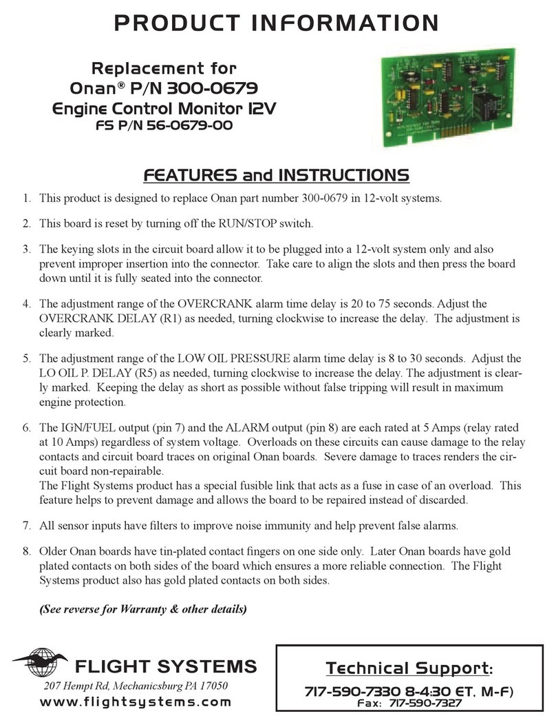
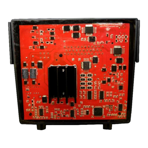
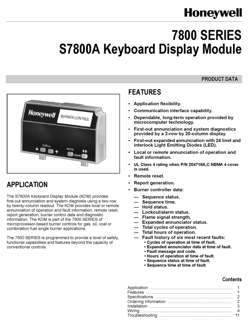
Flight Systems SCU 9iS User manual

Installation / Operation
Manual
SCU 9iS
System Control Unit
Version: 1.04 © Copyright 2021 RS Flight Systems GmbH

16.03.2021 | V1.04
-2-
Installation / Operation Manual
System Control Unit
Contents
..................................................................................................................................................................1
1. Preface..............................................................................................................................................3
2. System Description...........................................................................................................................3
3. Technical Specifications....................................................................................................................5
4. Mechanical Installation ....................................................................................................................7
4.1 Drawings SCU 9iS Main Unit....................................................................................................8
4.2 Drawings SCU Display Panel ...................................................................................................9
4.3 Drawings SCU Front Panel ....................................................................................................11
5. Electrical Installation ..................................................................................................................... 13
5.1 Lane A / Lane B / Lane C Connector ..................................................................................... 14
5.2 Auxiliary Connector ............................................................................................................... 15
5.3 External Connector ................................................................................................................ 17
5.4 Front Panel out Connector .................................................................................................... 18
5.5 Electrical Installation Front / Display Panel ........................................................................... 18
5.6 Wiring Diagram SCU ............................................................................................................. 20
5.7 Available Accessories ............................................................................................................ 21
6. Operation....................................................................................................................................... 22
6.1 Startup Power Relay Function............................................................................................... 22
6.2 Flight Data Recording ............................................................................................................ 22
6.3 Software Update .................................................................................................................... 26
7. Abbreviations and Terms............................................................................................................... 27

Installation / Operation Manual
System Control Unit
16.03.2021 | V1.04
-3-
1. Preface
Thank you for purchasing a System Control Unit from RS Flight Systems. We are pleased that you have
chosen our product and are confident that it will meet all your expectations. In case of questions or
problems with the unit, feel free to contact us:
RS Flight Systems GmbH
Oberer Luessbach 29-31
82335 Berg | Germany
Phone: +49-8178-8681-300
E-Mail: contact@rs-flightsystems.com
2. System Description
The System Control Unit (SCU) itself is based on the proven hardware of the second generation Engine
Management Unit family (EMU 912iS evo and EMU 9xiS). The stand-alone main unit offers the
following functionality:
•Automatic propeller speed control for Single Lever Power Control
(in combination with optional MT Propeller governor)
•Automatic throttle valve control for helicopter or UAV applications
(in combination with optional actuator system)
•Three optically isolated CANaerospace data bus interfaces for retained redundancy
•Engine Data transfer to CAN-based third party avionics systems (e.g. by Garmin or Dynon)
•Continuous monitoring and health checking of both ECU display buses
•Seamless integration into the Rotax 912iS / 915iS engine wiring harness
•Minimum installation effort (single device, 2 connectors and 6 wires for basic functionality)
•Remote installation possible
•Georeferenced data recording of all parameters at 10 Hz over up to 2000 hours
•Simple data transfer and software update via an integrated memory card slot
•Sophisticated visualization and processing tool for recorded data (Windows, Linux, MacOS)
•Google Earth file export for recorded data including GNSS and engine data
•Several additional input and output channels for future system upgrades
•Suitable for 14 V and 28 V aircraft electrical systems
•Preassembled wiring harnesses available as accessories
•Highly customizable software (available on request)
•High level of manufacturing and quality control
•Engineering and production exclusively done in Germany

16.03.2021 | V1.04
-4-
Installation / Operation Manual
System Control Unit
Figure 2-1: Top view of the SCU 9iS
Figure 2-2: SD Card Cover
In combination with either of the two optional extension units (Front Panel including switches or
Display Panel without switches), the following additional functions are offered:
•Indication of the most important engine parameters, engine status and ECU faults
•Simple and self-explanatory operation via three push buttons
•All necessary indicator lights for Rotax iS engine operation
•All necessary switches for Rotax iS engine operation
(Front Panel only, in combination with optional Start Power function)
Figure 2-3: SCU Display Panel
Figure 2-4: SCU Front Panel

Installation / Operation Manual
System Control Unit
16.03.2021 | V1.04
-5-
3. Technical Specifications
SCU 9iS Main Unit
Mechanical
Dimensions
(width, height, depth)
120 x 149 x 34 mm
4.72 x 5.87 x 1.34 in
Mounting
Hole Pattern
(width, height)
4 screws up to M4
92.4 x 137.6 mm
3.64 x 5.42 in
Total Mass
0.62 kg
1.37 lbs
Housing
Aluminum, painted black and machined, IP30 (ISO 20653)
Supply Voltage
9 to 32 Volts DC, according to EN2282
Power Consumption
typ. 7.0 W (0.3 A at 14 V, 0.18 A at 28 V) without external load
CANaerospace
Interfaces
According to ISO 11898-2, optically isolated
two input channels, one output channel
Analog I/O
4 inputs (±10 V)
Digital I/O
5 low-side inputs, 5 high-side inputs
14 outputs (7 low-side, 7 high-side) driving up to 2.4 A each
Positioning
Combined GPS/Galileo Sensor (Navilock NL-603P), 4 Hz update rate
Electronics
Xilinx Spartan-3 FPGA with dual Microblaze processors
Storage
Single side mounted SD/SDHC-Card, up to 32 GB
Operating
Temperature Range
-20 to +70 oC
-4 to +158 oF
Operating Altitude
< 7,620 m
< 25,000 ft
Humidity
< 95 %, non-condensing
Table 3-1: Technical Specification SCU 9iS Main Unit

16.03.2021 | V1.04
-6-
Installation / Operation Manual
System Control Unit
SCU Display Panel
SCU Front Panel
Mechanical
Dimensions
(width, height, depth)
90 x 66 x 23.5 mm
3.54 x 2.6 x 0.93 in
150 x 66 x 97.5 mm
5.91 x 2.6 x 3.84 in
Panel Cutout
(width x height)
82 x 58 mm, 12 mm corner radii
3.23 x 2.28 in, 0.47 in corner radii
142 x 58 mm, 12 mm corner radii
5.59 x 2.28 in, 0.47 in corner radii
Mounting
Hole Pattern
(width, height)
4 M4 screws
80 x 57 mm
3.15 x 2.24 in
4 M4 screws
142 x 58 mm
3.59 x 2.28 in
Total Mass
0.12 kg
0.26 lbs
0.4 kg
0.88 lbs
Housing
Aluminum, visible surfaces anodized to aerospace standard
Supply Voltage
12 V and 3.3 V, supplied by the SCU Main Unit
Lane A/B LEDs supplied by ECU / HIC connector
Power Consumption
typ. 0.5 W
Display
2.1 inch monochrome OLED display, 170° viewing angle,
100 x 32 pixels, typ. 100 cd/m²
Operating
Temperature Range
-20 to +70 oC
-4 to +158 oF
Operating Altitude
< 7,620 m
< 25,000 ft
Humidity
< 95 %, non-condensing
Table 3-2: Technical Specification SCU Extension Units

Installation / Operation Manual
System Control Unit
16.03.2021 | V1.04
-7-
4. Mechanical Installation
Upon delivery, undertake visual inspection of the package contents for signs of transport damage and
verify the information on the type plate sticker against your order. Do not open the device housing.
For longer storage of the device, select a dry and clean environment. Make sure that the device is not
stored near strong heat sources and that no metal chippings or other dirt can get into the device or its
connectors.
The SCU is mounted on a horizontal or vertical surface using four screws (max. diameter 4.0 mm) not
included in the package. The hole positions can be taken from Figure 4-1. If you are using fixed female
threads in the mounting surface instead of nuts, provide a minimum thread length of 4 mm. Always
secure your mounting joint. The Front and Display Panels require a rounded rectangular cutout (see
Figure 4-6 and Figure 4-8 ) and are mounted on the aircraft instrument panel using four M4 Philips
headed screws included in the package. Three-dimensional CAD-models of all units are available on
request.
As waste heat is dissipated via free convection, leave at least a 5 mm gap from the exterior surfaces
(excluding the mounting face) to any other object. Forced cooling is not necessary.
The installation must be in accordance with the appropriate guidelines approved by the respective
aviation authority. The person installing the device is responsible for compliance with all applicable
legislation.

16.03.2021 | V1.04
-8-
Installation / Operation Manual
System Control Unit
4.1 Drawings SCU 9iS Main Unit
Figure 4-1: SCU 9iS Main Unit (front view)
Figure 4-2: SCU 9iS Main Unit (side view)

Installation / Operation Manual
System Control Unit
16.03.2021 | V1.04
-9-
Figure 4-3: SCU9iS Main Unit (isometric view)
4.2 Drawings SCU Display Panel
Figure 4-4: SCU Display Panel (top view)
Figure 4-5: SCU Display Panel (side view)

16.03.2021 | V1.04
-10-
Installation / Operation Manual
System Control Unit
Figure 4-6: SCU Display Panel (front view)
Figure 4-7: SCU Display Panel (isometric view)

Installation / Operation Manual
System Control Unit
16.03.2021 | V1.04
-11-
4.3 Drawings SCU Front Panel
Figure 4-8: SCU Front Panel (front view)
Figure 4-9: SCU Front Panel (top view)
Figure 4-10: SCU Front Panel (side view)

16.03.2021 | V1.04
-12-
Installation / Operation Manual
System Control Unit
Figure 4-11: SCU Front Panel (isometric view)

Installation / Operation Manual
System Control Unit
16.03.2021 | V1.04
-13-
5. Electrical Installation
The SCU Main Unit has seven connectors on the front side. Six of them are standard density D-Sub
connectors with 4-40 UNC threaded fastening. All three CAN Connectors (“Lane A”, “Lane B” and “Lane
C”) are equipped with a filter adapter to enhance signal quality. Do not remove these filters. The
remaining DIN-style connector for the GNSS Antenna is secured with two safety wires.
Connector
Label
Connector Type
Usage
AUX
“AUX”
DA15S (female 15-pin D-Sub)
I/O
I/O
“EXT”
DB25S (female 25-pin D-Sub)
I/O
CANaero_A
“LANE A”
DE9P (male 9-pin D-Sub)
CAN Bus Input, Power Supply
CANaero_B
“LANE B”
DE9P (male 9-pin D-Sub)
CAN Bus Input
CANaero_C
“LANE C”
DE9P (male 9-pin D-Sub)
CAN Bus Output
FP
“PANEL OUT”
DE9S (female 9-pin D-Sub)
Connection to Extension Units
GNSS
“GPS INPUT”
Female Mini-DIN 6
GNSS Antenna
Table 5-1: Main Unit connectors
Place the GNSS antenna in a spot where it has maximum optical visibility of the sky, e.g. the glare shield
on top of the instrument panel. Poor GNSS reception has no adverse impact on the operation of the
unit yet may impair recordings of position, ground speed and UTC data.
Each of the extension units comes with two standard density D-Sub connectors with 4-40 UNC
threaded fastening on the rear of the display part. In case of the Front Panel, the ignition, auxiliary fuel
pump and battery backup power switches need to be connected using individual wires according to
the Installation Manual of the BRP Rotax engine.
Connector
Label
Connector Type
Usage
LED
“LED”
DE9P (female 9-pin D-Sub)
Annunciator Lights
Display
“SCU”
DE9S (male 9-pin D-Sub)
Connection to Main Unit
Table 5-2: Extension Unit connectors
Only use self-extinguishing cables suitable for installation in aircraft; e.g. SAE-AS22759 or SAE-
AS27500. AWG22 (0.34 mm²) is a sufficient cross section for power supply of the SCU. Preassembled
wiring harnesses are available as accessories for simplifying the installation. For part numbers see
Chapter 5.7 or contact RS Flight Systems directly.
Ensure that proper grounding connections are made and that the various ground potentials are not
connected outside of the Main Unit. This is especially important for the analog reference ground.
Figure 5-1 shows an overview of all standard connections.
Carefully check your wiring before powering up the unit for the first time.

16.03.2021 | V1.04
-14-
Installation / Operation Manual
System Control Unit
Figure 5-1: SCU Sub-D connector pin numbering
5.1 Lane A / Lane B / Lane C Connector
The Lane A Connector carries the power supply pins of the SCU (Pins 1 and 5) and Display CAN Lane A
(Pins 2 and 7). Table 5-3 specifies its pinout. Reverse polarity and voltage surge protection are
implemented on the Lane A connector, therefore power must be supplied there. Install a 3 A circuit
breaker or quick fuse in the positive supply line. For CAN wiring, use shielded twisted pair cables with
an impedance of 120 Ω. Do not connect either of the CAN Ground Pins available on the two Harness
Interface Connectors. Since termination resistors are built into the ECU as well as the SCU, no
additional resistors are necessary.
Pin Number
Signal Name
Function
1
PWR_IN
positive SCU power supply
2
CANL_A
CAN Low, connect to HIC A, Pin 5
3
EXT_PWR_ACT
do not connect
4
EXT_DIN2
do not connect
5
AC_GND
negative SCU power supply, ground
6
EXT_DIN0
do not connect
7
CANH_A
CAN High, connect to HIC A, Pin 6
8
EXT_DIN1
do not connect
9
LS_OUT1
do not connect
Table 5-3: Lane A pinout
The Lane B Connector carries the second Display CAN Lane of the ECU on Pins 2 and 7. This setup
guarantees full redundancy of all data paths to the SCU. Table 5-4 specifies its pinout.

Installation / Operation Manual
System Control Unit
16.03.2021 | V1.04
-15-
Pin Number
Signal Name
Function
1
PWR_IN
do not connect
2
CANL_B
CAN Low, connect to HIC B, Pin 7
3
EXT_PWR_ACT
do not connect
4
EXT_DIN5
do not connect
5
GND
do not connect
6
EXT_DIN3
do not connect
7
CANH_B
CAN High, connect to HIC B, Pin 8
8
EXT_DIN4
do not connect
9
SPARE
do not connect
Table 5-4: Lane B pinout
The Lane C Connector carries the third CAN Lane for the isolated output of the combined data from
Lanes A and B to a third party display via the CANaerospace protocol.
Pin Number
Signal Name
Function
1
RS422RXA
do not connect
2
CANL_C
CAN Low, connect to external display
3
RS422RXB
do not connect
4
RS422TXA
do not connect
5
RS422TXB
do not connect
6
GND
do not connect
7
CANH_C
CAN High, connect to external display
8
DEBUG_TXD
do not connect
9
DEBUG_RXD
do not connect
Table 5-5: Lane C pinout
5.2 Auxiliary Connector
The Auxiliary Connector is used for general I/O purposes. It offers regulated 12 V (Pin 13) and 5 V (Pin
11) reference voltages for sensors and can supply a maximum of 100 mA each. Both supplies are
referenced to a common ground (Pins 5 and 12) isolated from the aircraft supply potentials. The analog
inputs also refer to the same potential. The maximum analog input voltage is ±10 V. Note that higher
voltages can permanently damage the unit as no protection is implemented on these inputs. It is
recommended to use the analog inputs as shown in Table 5-6 and Figure 5-3.
It is recommended to place the optional fuel pressure sensor either as close as possible to the fuel
pressure regulator on the fuel rail of the left cylinder bank (Cylinders 2 and 4) or on the outflow port
of the fuel filter. The installation of the fuel pressure sensor on the fuel rail is marked in red in Figure
5-2. The available adapter (see Chapter 5.7) allows mounting it in both these places. A fuel pressure
sensor with the following specifications is available as an accessory and supported by the standard
software (see Chapter 5.7):

16.03.2021 | V1.04
-16-
Installation / Operation Manual
System Control Unit
•Pressure range: 1 to 11 bar absolute pressure
•Supply voltage: 5 or 12 V
•Output voltage: 0.5 VDC to 4.5 VDC
Figure 5-2: Fuel Pressure Sensor Installation
The standard hard- and software are designed to drive an electric MT-Propeller P-853 constant speed
governor via the MOTOR+ and MOTOR- (Pins 7 and 8) outputs (function available on request). The
exact variant of the governor depends on the specific aircraft configuration. Please contact RS Flight
Systems for further details. A prewired harness is available as an accessory (see Chapter 5.7).
Pin Number
Pin Name
Function
1
AIN0
Analog Input 0 (Fuel Pressure)
2
DIN6
do not connect
3
DIN7
do not connect
4
AIN3
Analog Input 3 (Governor Limit)
5
GND
Analog Input Reference Ground
6
START_PWR
Start Power Relay Output
7
MOTOR+
Propeller Governor H-Bridge Driver Output (High Side)
8
MOTOR-
Propeller Governor H-Bridge Driver Output (Low Side)
9
DIN5
do not connect
10
STARTER
do not connect
11
5V
5 V Analog Reference Voltage
12
GND
Analog Input Reference Ground
13
12V
12 V Analog Reference Voltage
14
A/C_GND
Aircraft Ground
15
GND
Internal Ground
Table 5-6: Auxiliary Connector pinout

Installation / Operation Manual
System Control Unit
16.03.2021 | V1.04
-17-
The START_PWR and STARTER relay outputs drive up to 500 mA of inductive load and are referenced
to the internal ground (Pin 15). The SCU uses these outputs to drive external start power and starter
relays to simplify or even automate the engine start procedure. Using the Start Power relay, the ECU
is automatically connected to the battery power during engine startup as opposed to the pilot
activating a spring loaded “Start Power” switch. The function is activated only after startup of the SCU
until the engine reaches 1500 rpm for the first time. Assoon as this condition is met, the ECU is supplied
by one of the internal generators. A separate, mechanically locking “Battery Backup” toggle switch (as
found on the SCU Front Panel) remains necessary in order to fulfil all safety requirements (e.g. for
engine restart in flight). An extinguishing diode across the relay coil is not needed and a suitable relay
is available as an accessory (see Chapter 5.7). The Starter relay is intended for use on unmanned
aircraft. Feel free to contact RS Flight Systems for different sensor and actuator configurations.
5.3 External Connector
The I/O connector offers filtered, but unregulated power output and further general I/O connections.
The digital inputs are referenced to aircraft ground (Pin 3).
The low-side outputs are referenced to the internal ground and the high-side outputs are referenced
to the power output.
Pin Number
Signal Name
Function
1
DIN9
do not connect
2
DIN10
do not connect
3
AC_GND
do not connect
4
LS_OUT2
do not connect
5
LS_OUT3
do not connect
6
LS_OUT4
do not connect
7
LS_OUT5
do not connect
8
LS_OUT6
do not connect
9
LS_OUT7
do not connect
10
GND
Internal Ground
11
GND
Internal Ground
12
GND
Internal Ground
13
GND
Internal Ground
14
GND
Internal Ground
15
LS_OUT0
do not connect
16
HS_OUT2
do not connect
17
HS_OUT3
do not connect
18
HS_OUT4
do not connect
19
HS_OUT5
do not connect
20
HS_OUT6
do not connect
21
HS_OUT7
do not connect
22
PWR
Power Output (9-32 V)
23
PWR
Power Output (9-32 V)

16.03.2021 | V1.04
-18-
Installation / Operation Manual
System Control Unit
24
PWR
Power Output (9-32 V)
25
PWR
Power Output (9-32 V)
Table 5-7: External Connector pinout
Feel free to contact RS Flight Systems for your needs regarding I/O applications. Examples are
automatically controlled LANE and fuel pump switches, temperature-controlled fan activation
(Intercooler, Oil cooler), UAV applications and many more.
5.4 Front Panel out Connector
The Front Panel out connector is the interface to the optional extension units. A suitable connection
harness between the main unit and the extension unit is available as an accessory (see Chapter 5.7).
The pinout of the Front panel out connector is listed in Table 5-8.
Pin Number
Signal Name
Function
1
PWR_IN 12V
positive Front Panel power supply
2
PWR_IN 3.3V
positive display power supply
3
OLED_SCK
Display control
4
OLED_MOSI
Display control
5
OLED_CS
Display control
6
TAST1
Button 1
7
TAST2
Button 2
8
TAST3
Button 3
9
GND
Internal Ground
Table 5-8: Front Panel Out Connector pinout
5.5 Electrical Installation Front / Display Panel
The pinout of the SCU connector is listed in Table 5-9. It is equal to the pinout of the Front Panel out
connector of the SCU main unit.
Pin Number
Signal Name
Function
1
PWR_IN 12V
positive Front Panel power supply
2
PWR_IN 3.3V
positive display power supply
3
OLED_SCK
Display control
4
OLED_MOST
Display control
5
OLED_CS
Display control
6
TAST1
Button 1
7
TAST2
Button 2
8
TAST3
Button 3
9
GND
Internal Ground
Table 5-9: SCU Connector pinout

Installation / Operation Manual
System Control Unit
16.03.2021 | V1.04
-19-
The pinout of the LED connector is listed in Table 5-10. For the connection of the warning lamps A and
B please refer to the BRP Rotax Installation Manual 912iS / 915iS. The pre-resistors and the parallel
resistors are integrated in the Front Panel and the Display Panel. Therefore, the pins 1-4 can be directly
connected to the BRP Rotax HIC A and HIC B connectors.
The Start/Backup Power LED (pin 5) can be connected in parallel to the Start Power Relay in order to
show the pilot the status of Start Power Relay function.
For the connection of the generator LEDs please refer to the manual of the generator.
Pin Number
Signal Name
Function
1
LANE_A
Warning Lamp Lane A
2
LANE_A_GND
Warning Lamp Lane A ground
3
LANE_B
Warning Lamp Lane B
4
LANE_B_GND
Warning Lamp Lane B ground
5
Backup_LED
Backup / Start Power LED
6
EMS_LED
EMS Power Controller LED
7
GEN_LED
Generator LED
8
GEN_LED_GND
Generator LED ground
9
Backup_EMS_GND
Backup / EMS Power LED ground
Table 5-10: LED Connector pinout

16.03.2021 | V1.04
-20-
Installation / Operation Manual
System Control Unit
5.6 Wiring Diagram SCU
Figure 5-3: Wiring Diagram
3 A SCU
Power Supply
Ground
1
5
2
7
CAN Low B
CAN High B
120 Ω
2
7
Lane A
CAN_LOW_1_LB
CAN_HIGH_1_LB
CAN_GND_1_LB
Auxiliary
7
8
6
7
8
6
CAN_LOW_1_LA
CAN_HIGH_1_LA
CAN_GND_1_LA
5
6
4
5
6
4
1
12
11
4
5
7
8
6
15
ECU HIC A
Main Bus
Aircraft GND
HIC B
FPS C
A
B
C
A
B
Governor 5
6
3
4
5
6
3
4
390 Ω
GNSS Antenna
SPR 0
1
1
12
11
4
5
7
8
6
15
2
4
6
8
CAN Low A
CAN High A
120 Ω
Fusebox 2
32
3
X3
Signal Input
Reference GND
5 V Reference
Stop Signal
Reference GND
Motor +
Motor -
Start Power
Aircraft GND
GNSS
EMS GND
Aircraft GND
1
5
2
7
2
7
STP
white
black
red
white
black
red
blue
DNC Aircraft GND
STP
DNC Aircraft GND
Third party
display
device with
CAN input
CAN Low C
CAN High C
120 Ω
2
7
Lane C
2
7
STP
Aircraft GND
Lane B
Table of contents
Other Flight Systems Control Unit manuals
