FLINT HILL FHG67ZR Instruction Manual

FHG67ZR
Aluminum
Cargo Carrier
with 41” Long Ramp
Instruction Manual
& Parts Catalog
Copyright © 2022 by Flint Hill Goods. All rights reserved. No portion of this manual or any artwork
contained herein may be reproduced in any shape or form without the express written consent of Flint
Hill Goods. Due to continuing improvements, actual product may differ slightly from the product
described herein. Tools required for assembly and maintenance may not be included.
READ AND UNDERSTAND THIS ENTIRE MANUAL BEFORE
ASSEMBLING, OPERATING OR SERVICING THIS PRODUCT.
SAVE THIS MANUAL.
LIT-00420, Rev -
IMPORTANT SAFETY
INSTRUCTIONS
WARNING concerning Risk of
Eye Injury. Wear ANSI approved
eye protection.
WARNING concerning Risk of
Hearing Loss. Wear hearing
protection.
INSTRUCTION
MANUAL
1. Read and understand all
safety warnings and
instructions. Failure to follow the
warnings and instructions may
result in serious injury or death.
Save all warnings and instructions
for future reference.
A. Always wear ANSI approved
safety goggles.
B. Always wear hearing
protection when working in
noisy environments. Prolonged
exposure to high intensity noise
can cause hearing loss.
C. Use safety equipment. Safety
shoes, hard hat, and work gloves
must be used for applicable
conditions.
2. Personal and Work Area Safety
D. Dress appropriately. Never wear loose
fitting clothing or jewelry when working.
Contain long hair, and keep hair, clothing
and gloves away from moving parts.
E. Use common sense when working.
Stay alert and concentrate when setting up
and using this Carrier. Never work while
under the influence of alcohol, drugs or
medications.
SAVE THIS MANUAL
Keep this manual for the safety warnings and
precautions. The manual offers important
information on how to assemble, use and
maintain this product. Write the product’s model
number and purchase date on the cover page
of this manual. Keep this manual (and your
purchase receipt) in a safe place.
UNPACKING
The shipment should be thoroughly inspected
as soon as it is received. The signed “bill of
lading” is acknowledgement by the carrier of
receipt in good condition or shipment covered
by our invoice. For your own protection, if any
of the goods called for on the bill of lading are
shorted or damaged, do not accept them until
the carrier makes a notation on the freight bill
of the shorted or damaged goods. Notify Flint
Hill Goods immediately if any hidden loss
or damage is discovered after receipt.
IMPORTANT SAFETY INFORMATION
DANGER
NOTICE
DANGER indicates a hazardous
situation which, if not avoided,
will result in death or injury.
WARNING indicates a hazardous
situation which, if not avoided,
could result in death or injury.
CAUTION indicates a hazardous
situation which, if not avoided,
could result in minor or moderate
injury.
NOTICE indicates important
information which, if not followed,
may cause damage to equipment.
This is a SAFETY ALERT symbol.
It is used to alert you to potential
personal injury hazards. Obey all
safety messages that follow this
symbol to avoid possible injury
or death.
WARNING
CAUTION
Model FHG67ZR
Page 2
LIT-00420, Rev -

Personal and Work Area Safety (continued)
F. While assembling and using the Carrier
keep work area clean and well lighted.
Keep spectators and children out of the
work area.
3. Use of the Carrier
A. The Carrier must be attached to a 2”
x 2” Class III or Class IV hitch receiver.
The hitch must be properly installed by a
quali ed service technician and be certi ed
to support the weight of this Carrier and its
contents (500 Lbs. capacity).
B. This Carrier is designed to transport
mobility wheelchairs and scooters, snow
blowers, lawn and garden equipment and
similar cargo. Do not modify the Carrier
and do not use this product for purposes
that it was not designed for.r.
C. Never exceed the maximum weight
capacity of 500 Lbs.
D. Be aware of the danger of “dynamic
loading”. This situation arises when a load
is dropped onto the Carrier, resulting in a
short term excessive load. Dynamic loading
can result in damage and failure of the
Carrier and/or hitch receiver and personal
injury to the person loading the Carrier.
E. Never load people or animals into the
Carrier. Keep children and spectators well
clear when loading and using this product.
F. Adhere to all Department of
Transportation (D.O.T.) requirements
when using this product. Use ropes
and straps to securely hold all cargo in place.
G. For the vehicle that will support the
Carrier, read all pertinent vehicle instructions
and warnings provided in the owner’s manual.
Make sure the vehicle’s engine is OFF,
with parking brake set, before loading or
unloading the Carrier.
H. Note the position of the vehicle’s
exhaust pipes before setting up the
carrier. Make sure exhaust pipes are not in
close proximity of the Carrier; flammable
goods in the Carrier could catch on fire due
to heat from exhaust. If this risk exists on
your vehicle, do not use the Carrier.
Never ride on the equipment being
loaded or unloaded into the Carrier.
Slowly roll the equipment into and out of the
Carrier per the equipment manufacturer’s
instructions. Maneuvering a heavy
wheelchair or other piece of equipment
up and down the Ramp can be strenuous
and dangerous. This should only be done
by individuals who are physically able to
handle the demands of this task.
J. Make sure that both legs of Ramp rest
solidly on a flat solid surface before at-
tempting to load and unload the Carrier.
K. The horizontal bottom side of Carrier
should not be higher than 14” from the
bottom of Ramp. Any attempt to use the
Ramp to load an object more than this 14”
vertical height is not safe.
L. Once Carrier is loaded, Ramp must be
in upright position and locked in place
with Pins and Lock Pins. The Ramp must
always be locked in the upright position
when the Carrier is being transported.
M. With Carrier attached to vehicle, never
exceed 55 MPH vehicle speed. Adhere to
all state and local vehicle regulations per-
taining to the use of carrier devices.
Keep in mind that the warnings
previously discussed cannot cover all
possible events and circumstances. It is
important that the persons loading/
unloading and using this product use
common sense at all times.
Model FHG67ZR
Page 3
LIT-00420, Rev -

Assembling and Setting Up the Aluminum
Cargo Carrier with 41” Long Ramp
1. Refer to the Parts List and Assembly
Diagram at the end of this manual and photos
on this page of an assembled Carrier when
following the steps below. Note: This
Carrier is designed to be assembled so that
Ramp (1) opens to “curb side” of vehicle
2. This Carrier requires complete assembly.
It is recommended that two people assemble
this product.
3. Lay the Carrier Base (2) out on a flat
surface for assembly. Note how the “U” shaped
Upper Brace (4) is assembled horizontally
above the Carrier Base using Middle Supports
(7), Vertical Supports (8), End Supports
with reflectors (9), and End Supports (10).
Note the position of the open end of “U”
shaped Upper Brace; Ramp (1) will later get
connected to this open end (and note position
of End Supports with Reflectors on back
of Carrier).
4. Start securing the Upper Brace to Carrier
Base by assembling the two Middle Braces
(7); use the following hardware: Small Head
Bolts (16) and Lock Nuts (17).
Model FHG67ZR
Page 4
5. Next, attach the two End Supports
With Re ectors (9) to further support the
Upper Brace/Carrier Base. These End
Supports With Reflectors go on back of .
Carrier Use same hardware: (16) and (17).
6. Next, attach 4 End Supports (without
reflectors) (10). Two are located on
opposite side of End Supports With Reflectors,
.
and two are located on short side of Upper
Brace. Again use same hardware: (16) and (17).
7. Now attach Vertical Supports (8) using
hardware (16) and (17) to nish the assem-
bly of the Upper Brace to the Carrier Base.
Make sure all hardware is tightly secured.
8. Turn the Carrier Base on end and Assemble
the Hitch Bar Assembly (3)to the underside
(see photo below). Note that Hitch Bar
protrudes out of front of Carrier (opposite
side of Reflectors). Use harware: Medium
Head Bolt (20), Washer (21), Large Washer
(23) and Lock Nut (22).
Hitch Bar
Assembly (3)
Tie Down
Hook (13)
Middle
Supports
(7)
Carrier
Base (2)
End Supports/
ector (9)
End
Supports
(10)
Vertical Supports (8)
Upper
Brace (4)
LIT-00420, Rev -
9. Attach a Tie Down Hook (13) to each
corner of the Carrier Base, using Washer
(14) and Nut (15) - see photo to left.
10. Attaching the Ramp (1) to the open
end of the Carrier Base (2): Use Large
Head Bolts (18) and Lock Nuts (19) to attach
the Ramp. Tighten hardware enough so that
the Ramp will pivot properly (see photo to
the left).
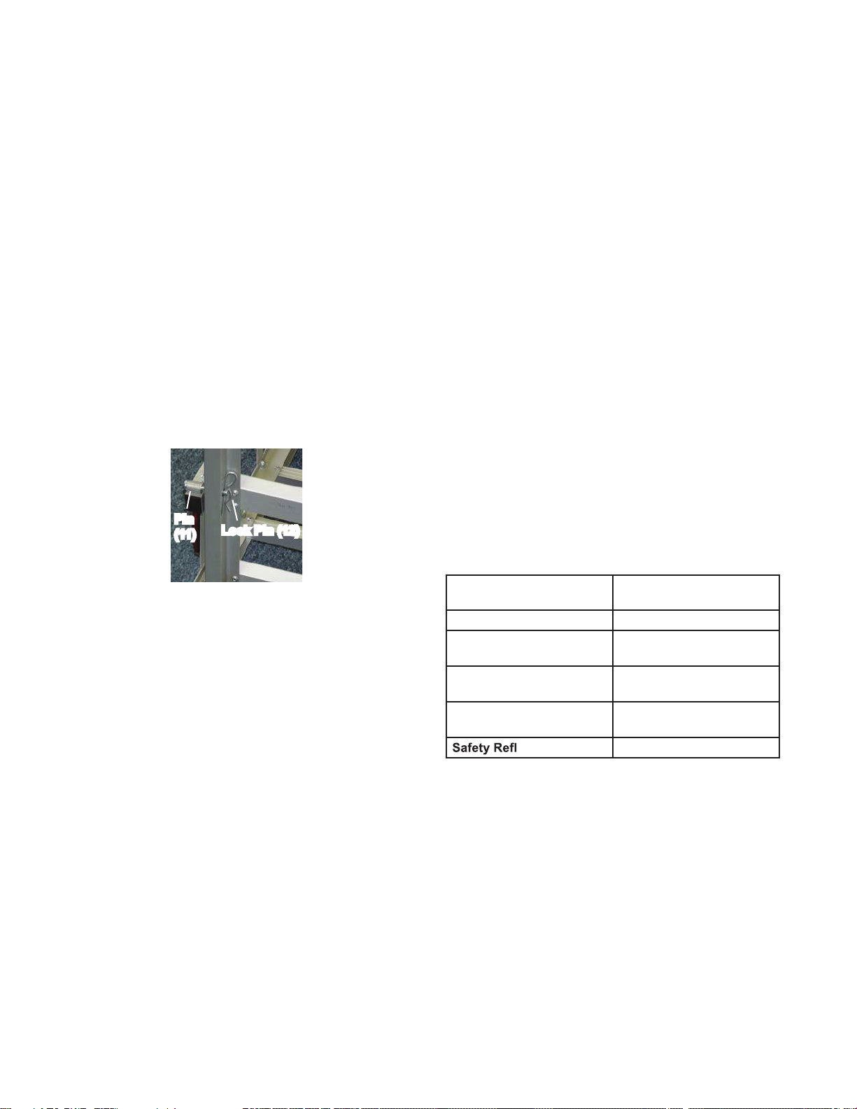
11. The Ramp will pivot upward to a vertical
SPECIFICATIONS
Maximum Weight
Capacity
500 Lbs.
Construction Extruded Aluminum
For Use With 2” x 2” Class III and IV
Hitch Receivers
Cargo Basket
Dimensions
47” L x 27-3/4” W x 7-1/2”
Deep
Hitch Pin 5/8” Diameter with Hitch
Lock Pin
ectors 2 Included
position, and is held in place using two Pins
(11) and two Lock Pins (12)
(see photo below).
12. The Carrier is now ready to be attached
to the vehicle’s receiver hitch.
With assistance, lift the Carrier and insert the
Carrier’s Hitch Bar Assembly (3) into the
vehicle’s receiver hitch. Insert the Hitch Pin (5)
through the hole openings in Hitch Bar and
receiver hitch. Secure the Hitch Pin with the
Hitch Lock Pin (6).
Loading and Unloading the Aluminum
Cargo Carrier
1. Once assured that the vehicle is located
in a safe, level location to load or unload the
Carrier, lower the Ramp (1). To lower Ramp,
take out the Lock Pins (12) and remove the
Pins (11). Lower Ramp making sure that
both legs of the Ramp are resting on a level
solid surface.
2. With an assistant, slowly push the
wheelchair/scooter/lawn equipment up the
ramp and into the Carrier. Use straps or
ropes attached to the Tie Down Hooks (13)
to secure the object being transported.
3. Raise the Ramp to the vertical closed
position (see photo on top of page 4), and
lock in place using two Pins (11) and Lock
Pins (12).
4.
To remove the equipment from the Carrier
lower the Ramp as described in paragraph
1 above. With assistance, carefully roll the
equipment down the Ramp. Once the
Carrier is unloaded, raise the Ramp and
secure it in the vertical position as described
in paragraph 3 above.
5. Periodically check the Carrier to insure
that all hardware is tightened securely.
Model FHG67ZR
Page 5
Pin
(11) Lock Pin (12)
LIT-00420, Rev -
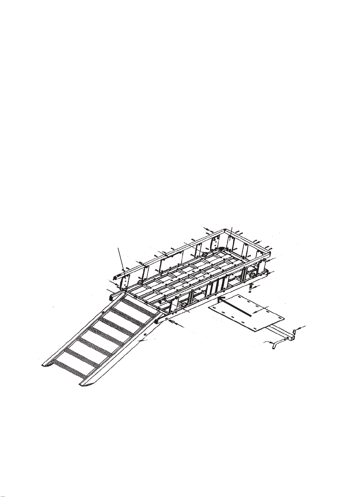
Assembly Drawing
Parts List
Note: The Parts List and Assembly Diagram is provided
as a reference tool only. Some parts are listed and shown
for illustration purposes only, and are not available as
replacement parts. All repairs to this tool (including
replacing parts) should only be done by a qualified
service technician.
Part # Description Qty
1 Ramp 1
2 Carrier Base 1
3 Hitch Bar Assembly 1
4 Upper Brace 1
5 Hitch Pin 1
6 Hitch Pin Lock 1
7 Middle Support 2
8 Vertical Support 5
9 End Support/Reflector 2
10 End Support 4
11 Pin 2
12 Lock Pin 2
13 Hook for Tie Down 4
14 Washer (M6) 4
15 Nut (M6) 4
16 Bolt, Small Head (M5x12) 46
17 Lock Nut (M5) 46
18 Bolt, Large Head (M8x30) 2
19 Lock Nut (M8) 2
20 Bolt, Med. Head (M6x45) 10
21 Washer (#6) 20
22 Lock Nut (M6) 10
23 Washer, Large 6
Part # Description Qty
TRAFFIC SIDE
CURB SIDE
2
9
8
7
13, 14, 15
16, 17 10
10
4
20, 21,
23, 22
1
18, 19
11, 12
5
6
3
Back of Carrier
(with reflectors)
When assembling this Carrier make sure the Carrier
Base and Ramp are oriented as shown in the Assembly
Drawing (with Reflectors facing rearward); for safety,
Ramp must open towards “curb side” of vehicle.
It can be hazardous to open the Ramp towards the
“traffic side” of vehicle.
Model FHG67ZR
Page 5
LIT-00420, Rev -
Table of contents
Other FLINT HILL Automobile Accessories manuals


Popular Automobile Accessories manuals by other brands


Cruz
Cruz Alu-Bike Assembly instructions

Fiamma
Fiamma 08452-01P Installation and usage instructions

Fiamma
Fiamma CARRY-BIKE PSA 02094-28A Installation and usage instructions

Fiamma
Fiamma 98655Z052 installation instructions

aFe Power
aFe Power 51-74201 instruction manual

Metra Electronics
Metra Electronics 99-5027 installation instructions