FLINT HILL FHG77ZR Instruction Manual

Scooter not included
FHG77ZR
Mobility Wheelchair
and Scooter
Carrier with 48”
Folding Ramp
Instruction Manual
& Parts Catalog
Copyright © 2022 by Flint Hill Goods. All rights reserved. No portion of this manual or any artwork
contained herein may be reproduced in any shape or form without the express written consent of Flint
Hill Goods. Due to continuing improvements, actual product may differ slightly from the product
described herein. Tools required for assembly and maintenance may not be included.
READ AND UNDERSTAND THIS ENTIRE MANUAL BEFORE
ASSEMBLING, OPERATING, OR SERVICING THIS PRODUCT.
SAVE THIS MANUAL.
LIT-00422, Rev -
IMPORTANT SAFETY
INSTRUCTIONS
WARNING concerning Risk of
Eye Injury. Wear ANSI approved
eye protection.
WARNING concerning Risk of
Hearing Loss. Wear hearing
protection.
INSTRUCTION
MANUAL
1. Read and understand all
safety warnings and
instructions. Failure to follow the
warnings and instructions may
result in serious injury or death.
Save all warnings and instructions
for future reference.
A. Always wear ANSI approved
safety goggles.
B. Always wear hearing
protection when working in
noisy environments. Prolonged
exposure to high intensity noise
can cause hearing loss.
C. Use safety equipment. Safety
shoes, hard hat, and work gloves
must be used for applicable
conditions.
2. Personal and Work Area Safety
D. Dress appropriately. Never wear loose
fitting clothing or jewelry when working.
Contain long hair, and keep hair, clothing
and gloves away from moving parts.
E. Use common sense when working.
Stay alert and concentrate when setting up
and using this Carrier. Never work while
under the influence of alcohol, drugs or
medications.
SAVE THIS MANUAL
Keep this manual for the safety warnings and
precautions. The manual offers important
information on how to assemble, use and
maintain this product. Write the product’s model
number and purchase date on the cover page
of this manual. Keep this manual (and your
purchase receipt) in a safe place.
UNPACKING
The shipment should be thoroughly inspected
as soon as it is received. The signed “bill of
lading” is acknowledgement by the carrier of
receipt in good condition or shipment covered
by our invoice. For your own protection, if any
of the goods called for on the bill of lading are
shorted or damaged, do not accept them until
the carrier makes a notation on the freight bill
of the shorted or damaged goods. Notify Flint
Hill Goods immediately if any hidden loss
or damage is discovered after receipt.
IMPORTANT SAFETY INFORMATION
DANGER
NOTICE
DANGER indicates a hazardous
situation which, if not avoided,
will result in death or injury.
WARNING indicates a hazardous
situation which, if not avoided,
could result in death or injury.
CAUTION indicates a hazardous
situation which, if not avoided,
could result in minor or moderate
injury.
NOTICE indicates important
information which, if not followed,
may cause damage to equipment.
This is a SAFETY ALERT symbol.
It is used to alert you to potential
personal injury hazards. Obey all
safety messages that follow this
symbol to avoid possible injury
or death.
WARNING
CAUTION
Model FHG77ZR
Page 2
LIT-00422, Rev -

Personal and Work Area Safety (continued)
F. While assembling and using the Carrier
keep work area clean and well lighted.
Keep spectators and children out of the
work area.
3. Use of the Carrier
A. The Carrier must be attached to a 2”
x 2” Class III or Class IV hitch receiver.
The hitch must be properly installed by a
to support the weight of this Carrier and its
contents (500 Lbs. capacity).
B. This Carrier is designed to transport
mobility wheelchairs and scooters, snow
blowers, lawn and garden equipment and
similar cargo. Do not modify the Carrier
and do not use this product for purposes
that it was not designed for.r.
C. Never exceed the maximum weight
capacity of 500 Lbs.
D. Be aware of the danger of “dynamic
loading”. This situation arises when a load
is dropped onto the Carrier, resulting in a
short term excessive load. Dynamic loading
can result in damage and failure of the Car-
rier and/or hitch receiver, and personal injury
to the person loading the Carrier.
E. Never load people or animals into the
Carrier. Keep children and spectators well
clear when loading and using this product.
F. Adhere to all Department of
Transportation (D.O.T.) requirements when
using this product. Use ropes and tie downs
to securely hold all cargo in place.
G. For the vehicle that will support the
Carrier, read all pertinent vehicle instructions
and warnings provided in the owner’s manual
Make sure the vehicle’s engine is OFF,
with parking brake set, before loading or
unloading the Carrier.
H. Note the position of the vehicle’s
exhaust pipes before setting up the Carrier
Make sure exhaust pipes are not in close
from exhaust. If this risk exists on your
vehicle, do not use the Carrier.
I. Never ride in the equipment being loaded
or unloaded into the Carrier Slowly roll
the equipment into and out of the Carrier per
the equipment manufacturer’s instructions.
Maneuvering a heavy wheelchair or other
piece of equipment up and down the
Ramp can be strenuous and dangerous.
This should only be done by individuals
who are physically able to handle the
demands of this task.
J. Make sure that the front edge of the
before attempting to load and unload the
Carrier.
K. The horiontal bottom side of Carrier
should not be higher than 14” from the
bottom of Ramp. Any attempt to use the
Ramp to load an object more than this 14”
vertical height is not safe.
L. Once Carrier is loaded, Ramp must be
in upright position and locked in place
with Safety Pins and R-Pins.
M. With Carrier attached to vehicle, never
exceed 55 MPH vehicle speed. Adhere to
all state and local vehicle regulations
pertaining to the use of carrier devices.
Keep in mind that the warnings
previously discussed cannot cover all-
possible events and circumstances.
It is important that the person loading/
unloading and using this product use
common sense.
N. WARNING! Avoid finger/hand injury
When attaching hitch accessory to
the vehicle’s hitch receiver,
NEVER insert finger into hitch pin
holes in an attempt to align
accessory to hitch receiver;
serious injury to fingers/hands
could occur.
Model FHG77ZR
Page 3
PINCH POINT!
Keep Hands Clear
WARNING
LIT-00422, Rev -
Assembling and Setting Up the Mobility
Wheelchair and Scooter Carrier
1. Refer to the Parts List and Assembly
Diagram at the end of this manual when
following the steps below. Note: This
Carrier is designed to be assembled so
that Ramp (6) opens to “curb side” of
vehicle. See Warning on page 6.
2. Set the Carrier Platform (1) on a solid
work surface. If necessary, remove the two
Safety Pins (2) and two R-Pins (23), and
swing open the Ramp (6) so it also lays on
the solid work surface.
The Ramp is heavy.
Use the handle on the underside when
lifting the Ramp; be careful not to pinch
side of Carrier Platform using Spring
Washer (11) and Nut (10).
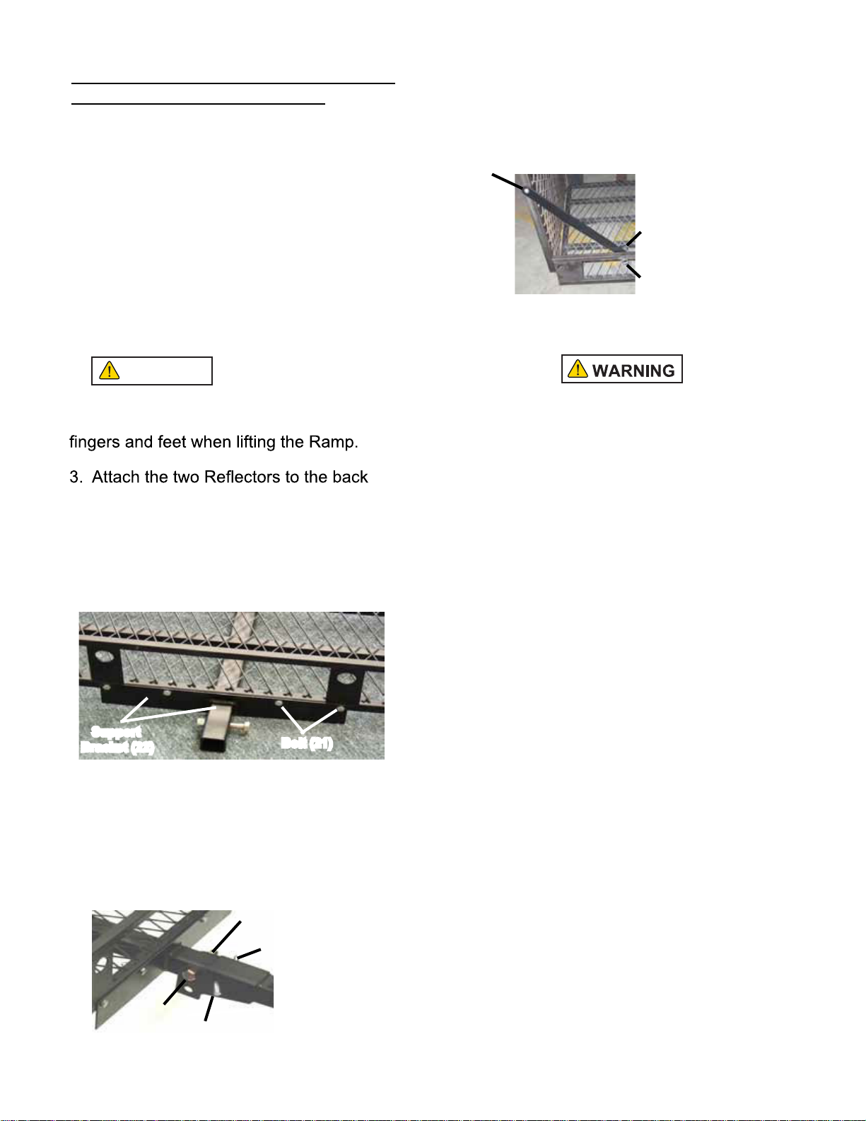
4. Attach Support Bracket (22) to underside
of Carriage Platform using 8 Bolts (21) and
Locking Nuts (5) - see photo below.
5. Assemble Hitch Tube (17) to front portion
of Support Bracket (22); align hole openings
for bolts and hitch pins. Lock Hitch Tube in
place with Bolt (20) and Locking Nut (19),
and Hitch Pin (18) and Lock Pin (16) - see
photo below.
6. Swing up Ramp (6) to the vertical posi-
tion. Lock Ramp in this position using the
two Safety Pins (2) and two R-Pins (23) -
see photo below.
Make sure R-Pins are fully inserted into
each Safety Pin (2).
The Carrier must be attached to a 2” x 2”
Class III or Class IV hitch receiver.
7. To place the Carrier on the vehicle’s hitch
receiver:
A. First remove the R-Pin (16) and
then the Hitch Pin (18), both located on
the Hitch Tube (17).
B. Slide the Anti-Tilt Locking Bracket
(15) over the end of the Hitch Tube. The
large open end of Anti-Tilt Locking Bracket
will face front and engage with vehicle’s
hitch receiver.
C. With a helper, lift the empty
Carrier and slide the open end of the Hitch
Tube into the vehicle’s 2” x 2” hitch receiver.
D. Align the hole openings on hitch
receiver and Hitch Tube, and put the
Receiver Pin (18) in place. Secure Receiver
Pin with the R-Pin (16).
Bolt (21)
Support
Bracket (22)
Safety Pin (2)
R-Pin (23)
Locking
Nut (19)
Bolt (20)
Hitch Pin (18)
Lock Pin (16)
Connecting Bar (3)
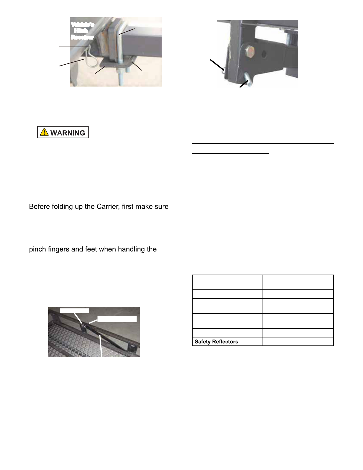
E. Place the Hitch Tightener - Clamp
Plate (24) under the leading edge of the
vehicle’s hitch receiver. The angled lip of
Hitch Tightener Plate rests against the
bottom side of the Hitch Mount Carrier’s Hitch
Bar (17). Slide Hitch Tightener U-Bolt (25)
over the Hitch Bar and secure U-Bolt from
the underside with Flat Washer, Spring
Washer and Nut (15,14,13). See photo
below. Model FHG77ZR
Page 4
CAUTION
LIT-00422, Rev -
SPECIFICATIONS
Maximum Weight
Capacity
500 Lbs.
Construction All Steel Square Tubular
For Use With 2” x 2” Class III and IV
Hitch Receivers
Cargo Basket
Dimensions
48-1/4” x 28-1/2” x 4”
Hitch Pin 5/8” Diameter with R-Pin
2 Included
8. Swing open the Ramp so it contacts the
ground and load the Carrier as needed. Use
ropes and tie downs to securely hold all
cargo in place.
Do not exceed the 500
Lbs. maximum weight capacity. Weight
inside the Carrier should be evenly
distributed.
9. When the Carrier is empty and not in use,
it can be left attached to the vehicle, and
folded up to a vertical position.
that the Ramp (6) is swung up and resting
on top of the Carrier Platform. The Ramp
is heavy. Use the handle on the underside
when lifting the Ramp; be careful not to
Ramp.
The two Connecting Bars (3) should be
positioned as shown in photo below. Secure
Connecting Bars with Safety Pins (2) and
R-Pins (23).
10. Folding Carrier to vertical position: With
assistance, remove Lock Pin (16) and Hitch
Pin (18). Carefully pivot the Carrier to the
vertical position - see photo below.
Connecting Bar (3)
Safety Pin (2)
R-Pin (23)
Align the hole openings on Support Bracket
(22) and Hitch Tube (17), and insert Hitch
Pin (24) in the hole below Bolt (20). Secure
Hitch Pin by fully inserting the Lock Pin (16).
Check to make sure that the Carrier is
secure in this fold-up position.
Maintaining the Mobility Wheelchair
and Scooter Carrier
1. Frequently check the condition of the
Carrier and the vehicle’s hitch receiver.
Make sure all components are in good
condition. If the Carrier or hitch receiver
become damaged through accident, or if any
weld damage is noted, the product should be
replaced.
Check to make sure that all hardware is
tightly secured in place.
2. Keep the Carrier clean.
Hitch Pin (18) location when Carrier
is folded to vertical position
Lock
Pin (16)
Vehicle’s
Hitch
Receiver
Hitch Tightener-
Clamp Plate (24)
Angled
Lip
Hitch Tightener
Hitch Bar
U-Bolt (25)
Hitch Pin (18)
hidden from view
Safety Pin (16)
Model FHG77ZR
Page 5
LIT-00422, Rev -

Parts List
Part # Description Qty. Part # Description Qty.
1 Carrier Platform 1
12 2
2 Safety Pin 2
13 Nut 2
3 Connecting Bar 2
14 Spring Washer 2
4 Bolt 2
15 Washer 2
5 Locking Nut 10
16 R-Pin 2
6 Ramp 1
17 Hitch Tube 1
7 Hinge 6
18 Receiver Pin 2
8 Washer 6
19 Locking Nut 1
9 Safety Pin 6
20 Bolt 1
10 Nut 4
21 Bolt 8
11 Spring Washer 4
22 Support Bracket 1
23 R-Pin 2
24 Hitch Tightener-
Clamp Plate
1
25 Hitch Tightener-
U-Bolt
1
Assembly Drawing
Note: The Parts List and Assembly Diagram is provided
as a reference tool only. Some parts are listed and shown
for illustration purposes only, and are not available as
replacement parts. All repairs to this tool (including replacing
parts) should only be done by a qualified service technician.
TRAFFIC SIDE
When assembling this Carrier
make sure the Carrier Platform
and Ramp are oriented as
shown in the Assembly
Drawing (with Reflectors facing
rearward); for safet y, Ramp
must open towards “curb side”
of vehicle. It can be hazardous
to open the Ramp towards the
“traffic side” of vehicle.
CURB SIDE
Support Bracket (22) is assembled
underneath Carrier Platform (1)
Model FHG77ZR
Page 6
LIT-00422, Rev -
Table of contents
Other FLINT HILL Automobile Accessories manuals


Popular Automobile Accessories manuals by other brands


Toyota
Toyota PZ 416 - T0968 - 00 installation manual

Metra Electronics
Metra Electronics 99-7319 installation instructions

HydraBed
HydraBed Reel Lift Retrieval System installation guide

Volvo
Volvo 31213723 installation instructions

Racelogic
Racelogic PerformanceBox manual

ClearView
ClearView EXPANDA EXP-02 Assembly instructions