Flintec KEK-4 User manual


Junction Box Type KEK-4 Technical Manual Rev. 2.0.0 December 2022 Seite/ Page 2/12
Inhaltsverzeichnis / Table of Contents
Produkthaftung...................................................................................................................................................3
Sicherheitshinweise.............................................................................................................................................3
Technische Daten...............................................................................................................................................4
Mechanische Installation....................................................................................................................................5
Elektrische Anschlüsse........................................................................................................................................5
Anschluss der Wägezellenkabel .........................................................................................................................5
Auswahl des 4-Leiter und 6-Leiter Betriebes....................................................................................................6
Anschluss des Ausgangskabels ..........................................................................................................................6
Eckenabgleich bei Waagen mit FLINTEC-Wägezellen ......................................................................................7
Verschließen des Kabelkastens ..........................................................................................................................7
Safety Instructions .............................................................................................................................................8
Technical Data ....................................................................................................................................................9
Mechanical Installation.....................................................................................................................................10
Electrical Connections.......................................................................................................................................10
Load Cell Cable Connection ..............................................................................................................................10
Terminal designation Selection of 4-wire and 6-wire operation...................................................................11
Output Cable Connection..................................................................................................................................11
Corner Correction at Scales with Flintec Load Cells........................................................................................12
Closing the cable box ........................................................................................................................................12
Junction Box Type KEK-4 Technical Manual Rev. 2.0.0 December 2022 Seite/ Page 3/12
PRODUKTHAFTUNG
Alle Rechte vorbehalten.
Kein Teil dieser Veröffentlichung darf ohne vorherige schriftliche Genehmigung durch die Flintec GmbH
kopiert, gespeichert oder in irgendeiner Form oder mit irgendwelchen Mitteln übertragen oder wieder-
verwendet werden sei es mechanisch, fotokopiertechnisch oder jegliche andere Form der Vervielfältigung
und Archivierung.
Im Hinblick auf den Gebrauch der enthaltenen Information ist sich die Flintec GmbH keinerlei Verstoßes
gegen das Patentrecht bewußt. Trotz größter Sorgfalt bei der Erstellung dieses Handbuchs übernimmt
Flintec keinerlei Verantwortung für Fehler oder Auslassungen in diesem Handbuch. Jegliche
Haftungsansprüche für Schäden, die durch Gebrauch der in diesem Handbuch enthaltenen Information
entstehen können, werden ausgeschlossen.
Der Inhalt dieses Handbuchs wird als richtig und zuverlässig betrachtet. Sollten jedoch Fehler jeglicher Art
gefunden werden, dann ist die Flintec GmbH um jeden Hinweis dankbar. Flintec kann allerdings keinerlei
Haftung für direkte oder indirekte Schäden übernehmen, die durch den Gebrauch dieses Handbuchs
entstehen können.
Die FLINTEC GmbH bewahrt sich das Recht, dieses Handbuch jederzeit ohne vorherige Ankündigung zu
überarbeiten und den Inhalt zu verändern.
Weder Flintec noch alle angeschlossenen Tochtergesellschaften können von dem Käufer dieses Produktes
oder Dritten haftbar gemacht werden für Schäden, Verluste, Kosten oder sonstige Ausgaben, die in Folge von
Unfall, falscher Anwendung und Missbrauch dieses Produktes oder unbefugter Modifikation, Reparatur oder
Veränderung am Produkt oder durch den Ausfall bei sachgemäßer Verwendung gemäß den Flintec
Bedienungs- und Wartungsanleitungen angefallen sind.
FLINTEC kann nicht haftbar gemacht werden für Schäden oder Probleme, die durch die Anwendung von
Zubehör oder anderen Verbrauchsgütern enstanden sind, die nicht als originale Flintec Produkt ausgewiesen
sind.
Wichtig: Änderungen am Inhalt dieses Handbuchs ohne vorherige Ankündigung sind vorbehalten.
SICHERHEITSHINWEISE
VORSICHT LESEN Sie diese Handbuch VOR dem Betrieb oder der Wartung des Gerätes.
BEFOLGEN Sie die Anweisungen sorgfältig. Bewahren Sie dieses Handbuch als Nachschlagewerk
sicher auf. ERLAUBEN SIE KEINER ungeschulten Person die Bedienung, Reinigung, Überprüfung,
Reparatur oder Eingriff in dieses Gerät. TRENNEN Sie das Gerät IMMER vom Spannungsnetz bevor
Reinigungs- oder Wartungsmaßnahmen ausgeführt werden. KONTAKTIEREN Sie FLINTEC für
Information, Service und Ersatzteile.
WARNUNG ERLAUBEN SIE NUR BERECHTIGTEN PERSONEN DEN SERVICE AN DIESEM GERÄT.
LASSEN SIE SORGFALT WALTEN BEIM PRÜFEN, TESTEN UND EINSTELLEN, WENN DAS GERÄT UNTER
ELEKTRISCHER SPANNUNG STEHT. EINE MISSACHTUNG KANN ZU KÖRPERSCHÄDEN FÜHREN.
WARNUNG FÜR DAUERHAFTEN SCHUTZ GEGEN ELEKTRISCHE GEFAHREN DARF DAS GERÄT
NUR AN EINEM SPANNUNGSVERSORGUNGSNETZ MIT FUNKTIONSFÄHIGER VERBINDUNG ZUR
SCHUTZERDE BETRIEBEN WERDEN. ENTFERNEN SIE NIEMALS DIE VERBINDUNG ZUM
SCHUTZKONTAKT/SCHUTZLEITER.
WARNUNG TRENNEN SIE ALLE VERBINDUNGEN ZUR SPANNUNGSVERSORGUNG BEVOR DIE
SICHERUNG GEWECHSELT WIRD ODER SONSTIGE SERVICEARBEITEN AUSGEFÜHRT WERDEN.
WARNUNG VOR DEM ANSCHLIESSEN/TRENNEN VON INTERNEN ELEKTRISCHEN
KOMPONENTEN ODER DEM VERBINDEN MIT ELEKTRISCHEN GERÄTEN TRENNEN SIE IMMER DIE
SPANNUNGSVERSORGUNG UND WARTEN SIE FÜR MINDESTENS 30 (DREISSIG) SEKUNDEN BEVOR SIE
DIESE MASSNAHMEN AUSFÜHREN. EIN NICHTBEACHTEN DIESER WARNUNG KANN ZU EINEM
GERÄTESCHADEN ODER ZUR ZERSTÖRUNG DES GERÄTES ODER ZU KÖRPERSCHÄDEN FÜHREN.
VORSICHT ERGREIFEN SIE ALLE VORSICHTSMASSNAHMEN FÜR DEN UMGANG MIT
ELEKTROSTATISCH EMPFINDLICHEN GERÄTEN.
Junction Box Type KEK-4 Technical Manual Rev. 2.0.0 December 2022 Seite/ Page 4/12
TECHNISCHE DATEN
Typenbezeichnung
KEK- 4 v2.0
Gehäusematerial
Edelstahl
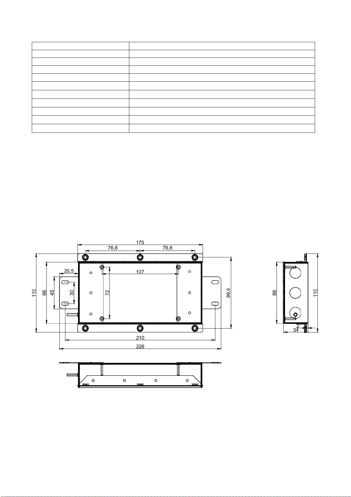
Gehäuseabmessungen
105 x 210 x 35 mm
Schutzart
IP 65
Anzahl Wägezellen
bis zu 4 Wägezellen mit 4 oder 6 Leiter Anschluß.
Anschluß
Federklemmen bis 2,5 mm2
Kabelein- bzw. Ausgänge
5x PG9
Kabeldurchmesser
4-8 mm
Eckenkorrektur
Über Festwiderstände im Signalzweig
Erdung
Über Schraubklemmung M3
Überspannungsschutz
Optional auf Anfrage
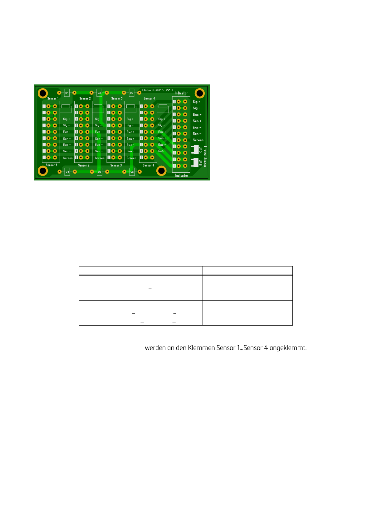
Der Edelstahl-Anschlußkasten KEK- 4 ist für den Parallel-Anschluss von bis zu 4 Wägezellen vorbereitet.
Es können 4- oder 6- adrige Wägezellen angeschlossen werden. Die Umschaltung zwischen 4-Leiter und 6-
Leitertechnik erfolgt mit Einlegebrücken.
Die Eckenkorrektur erfolgt mit Festwiderständen. **
Außerdem wurde der Anschlußkasten für den Einbau von Überspannungsableitern vorbereitet.
**Hinweis: 50 ppm Widerstände für den Eckenabgleich sind als Satz mit 14 Werten von 0,22 bis 4,7
(jeweils 10 Stück)unter der Artikel -Nr. 5200-030 lieferbar
Abbildung 1: Abmessungen in [mm]
Junction Box Type KEK-4 Technical Manual Rev. 2.0.0 December 2022 Seite/ Page 5/12
MECHANISCHE INSTALLATION
Als Einbauort sollte ein möglichst trockener und vor Umwelteinflüssen geschützter Ort gewählt werden.
Es ist zu empfehlen den Anschlußkasten über die äußere Schraubklemmung zu erden.
ELEKTRISCHE ANSCHLÜSSE
ANSCHLUSS DER WÄGEZELLENKABEL
Die jeweilige Kabelverschraubung muß gelockert werden. Danach wird das Wägezellenkabel soweit in die
Verschraubung eingeführt, bis der Schrumpfschlauch vollständig in der Verschraubung verschwindet. Der
Schrumpfschlauch bietet meist keinen Schutz vor Feuchteeintrag.
Danach können die Anschlussleitungen wie folgt aufgelegt und festgeklemmt werden:
Funktion
Klemmenbezeichnung
Signal +
Sig +
Signal
Sig -
Speisung + / Excitation +
Exc +
Rückführung + / Sense + *
Sen + *
Speisung / Excitation
Exc -
Rückführung / Sense *
Sen - *
* bei Wägezellen mit 6-Leiter Anschluss
Die bis zu 4 anschließbaren Wägezellen
Die Kabelfarben, bzw. die Funktion der einzelnen Adern entnehmen Sie bitte dem Datenblatt der Wägezelle
oder des Sensors.
Die Anschlussreihenfolge der Wägezellen sollte mit den Ecken der Waage übereinstimmen, also
Ecke 1 = Wägezelle / Sensor 1, Ecke 2 = Wägezelle / Sensor 2, usw.
Wenn alle Leitungen angeklemmt sind, müssen die Hutmuttern festgezogen werden. Bitte prüfen Sie
anschließend, ob Dichtigkeit und Zugentlastung vorhanden sind.
Other manuals for KEK-4
1
Table of contents
Languages:


