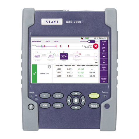
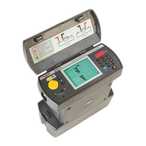
Flintec LCT-11 Instruction manual

LCT-11 Quick User Guide Rev.1.1.0, November 2020 Page 1of 3
LCT-11 Quick User Guide
1. Before the instrument can be used for the first time you have to insert 4
batteries of type AA. The battery box can be accessed from the rear side of
the instrument after the protective cover has been removed. After the
batteries have been inserted you can refit the protective cover.
2. The Instrument is off. If this is not the case please turn off the instrument by
pressing the <On/Off> key for approx. 5 seconds.
3. Connect the wires of the oad cell cable to the correct pins of the input
connector, but make sure that the SCREEN and the BODY are NOT
connected.
4. Power on the instrument by pressing the <On/Off> key for approx. 2
seconds.
5. The display will show the “Welcome” screen for a few seconds. Then it will
ask for the load cell connection type: 4-wire OR 6-wire.
6. For the best accuracy of the high resistance measurements (leakage) it’s
now a good opportunity to run a calibration. Press the <↓>and the
<On/Off> key simultaneously. The display will show “Calibrating”...and after
2 seconds the instrument is calibrated.
7. Now connect the SCREEN and the BODY (of the load cell) to the input
connector.
8. Select your load cell connection type (4-wire or 6-wire) and press <Enter>.
9. Select the rated output of the load cell with the <↑>and <↓>keys and press <Enter>.
10. Press the <Enter> button for a full load cell test cycle OR press the <↓>key for the continuous display
mode (GAIN).
If the Full load cell test cycle was selected:
The LCD will display “Test in progress” and the LED will flash for a few seconds. Once the test cycle is
finished you may scroll the results by pressing the <↑> key.
The results will be displayed in the following sequence:
Input
Resistance between Ex+ and Ex- (Max. 5000 ohm)
Output
Resistance between Signal+ and Signal- (Max. 5000 ohm)
Sense+
Resistance between Ex+ and Sense+ (Max. 500 ohm; valid for 6-wire cables only)
Sense-
Resistance between Ex- and Sense- (Max. 500 ohm; valid for 6-wire cables only)
Signal output
Load cell signal in percentage of full load cell capacity
Note: In case of a broken cable or a very high input/output resistance the display
will show “Can not measure”
Shield to bridge
Insulation resistance between the cable shield (screen) and the bridge
Body to bridge
Insulation resistance between the load cell body and the bridge
Shield to body
Resistance between the cable shield (screen) and the load cell body

LCT-11 Quick User Guide Rev.1.1.0, November 2020 Page 2of 3
If the Continuous display mode was selected:
The LED will flash in various colours and the load cell signal will be displayed continuously in
percentage of the full load cell capacity.
For example: applying 10 kg load on a 100 kg load cell will show a value of 10%
Note: To increase the battery lifetime the instrument will shut off after 6 minutes if no key was pressed.
Tips for Trouble Shooting Load Cells and Scales
Load cells might be damaged due to many reasons: Overloading, overvoltage, moisture or chemical ingress,
vibrations, corrosion, pulling the cable etc. As a result a scale may provide unstable readings, zero drifting, error
reading, non-linearity etc.
The LCT-11 is the only measuring tool required to perform the tests either on site or in the lab. Before you start,
make sure to have the load cell specifications and the cable colour code available (usually you get the
information with the load cell, or you can find it on the internet: see www.flintec.com).
How to test a weighing platform with a few load cells:
1. Preparation: Leave all load cells connected to the junction box. Disconnect the cable from the weighing
indicator and connect it to the LCT-11.
2. Perform a test. The expected results for an error-free scale are as per the following example:
If the scale consists of 4 load cells (1 kΩresistance and 100 kg capacity each) and 40 kg are applied as total
load (dead load + test weight), then you would expect to see around 250 Ω for the input and the output (total
of the input respective output resistance divided by the number of load cells, here this is 4).
In case of 6-wire cables you should expect to get very low resistance values between the sense lines and the
input (according to the cable resistivity) as those wires are shorted inside the load cell. In this example the
signal output must be around 10% (total load cell capacity is 400 kg) and the insulation resistance (Body to
Bridge and Shield to Bridge) must remain very high, i.e. > 3 GΩ.
3. If some of the results are not in the required range, or you get erratic / unstable readings when testing in the
Continuous display mode: Check the junction box for moisture and dirt (leakage current?, leftover flux from
soldering?) Check the cable integrity between the junction box and the instrument. If everything looks fine,
disconnect each load cell cable and check each load cell separately.
Note: At the moment there is no need to remove the load cell from the scale.
4. If all results seem to be in the range, you may check the scale for linearity, by selecting Continuous display
mode on the LCT-11 and applying various test weights on the scale.

LCT-11 Quick User Guide Rev.1.1.0, November 2020 Page 3of 3
Understanding the LCT-11 Test results:
Test result with LCT-11
Possible reasons
What to do?
Input / Output resistance not in the
expected range
Cable or connector problem
Check the cable integrity and the
connectors
Problems inside the load cell
Replace the load cell
Sense is too high (6-wire load cell)
Excitation and Sense not connected
inside the load cell or 4-wire load cell was
tested as a 6-wire type
Replace the load cell
Signal output from the scale is not in
the expected range
Corrosion, force shunts, accumulated
dust below the load cell or a faulty load
cell, dirty or humid junction box
Clean the dust and check for force
shunts and alignment. Replace the
load cell if necessary
Signal output of the unloaded scale is
not in the expected range (target
value according to the scale’s dead
load)
One or more load cells are damaged due
to a mechanical shock or overload
Replace the load cells
Insulation resistance (Body to bridge /
Shield to bridge) is too low
Insulation error due to water or chemical
ingress to the cable or into the load cell
Replace the cable and / or the load
cell
Special Instructions for Measuring the Insulation Resistance on a Load Cell:
1. Measuring the insulation resistance on a load cell requires special care and cleanness. Small errors when
executing the tests may lead to wrong results.
2. The ambient conditions must be dry, clean, dust-free and free from grease. The underlay has to be of non-
conductive material. Electrostatic charges will influence the measurement result.
3. The input connector has to be dry, clean and corrosion-free. Please take care for the correct fit. The cable of
the load cell has to be absolutely dry and clean. If required dry and clean it. If necessary make a clean strip of
the cable end.
4. Connect the wires of the load cell cable to the correct pins of the input connector, but make sure that the
SCREEN and the BODY are NOT connected.
5. Please don’t touch and move the cable during the measurement.
6. During the measurement the operator should be the only person within a 1 m distance from the test stand.
When the instrument is measuring he should not move.
7. Power on the instrument. Then press the <On/Off> and the <↓> keys simultaneously for approx. 2 seconds.
This will start a measurement for the connected cable.
8. Connect the SCREEN and the BODY (of the load cell) to the input connector and subsequently start a load
cell test cycle.
9. Generally verify the repeatability of the measurement results.
Battery information
Please note that if the device is not used for a longer period (we recommend 3 days), the batteries must be
removed from the LCT-11. If the batteries leak, they may damage the device
Table of contents

