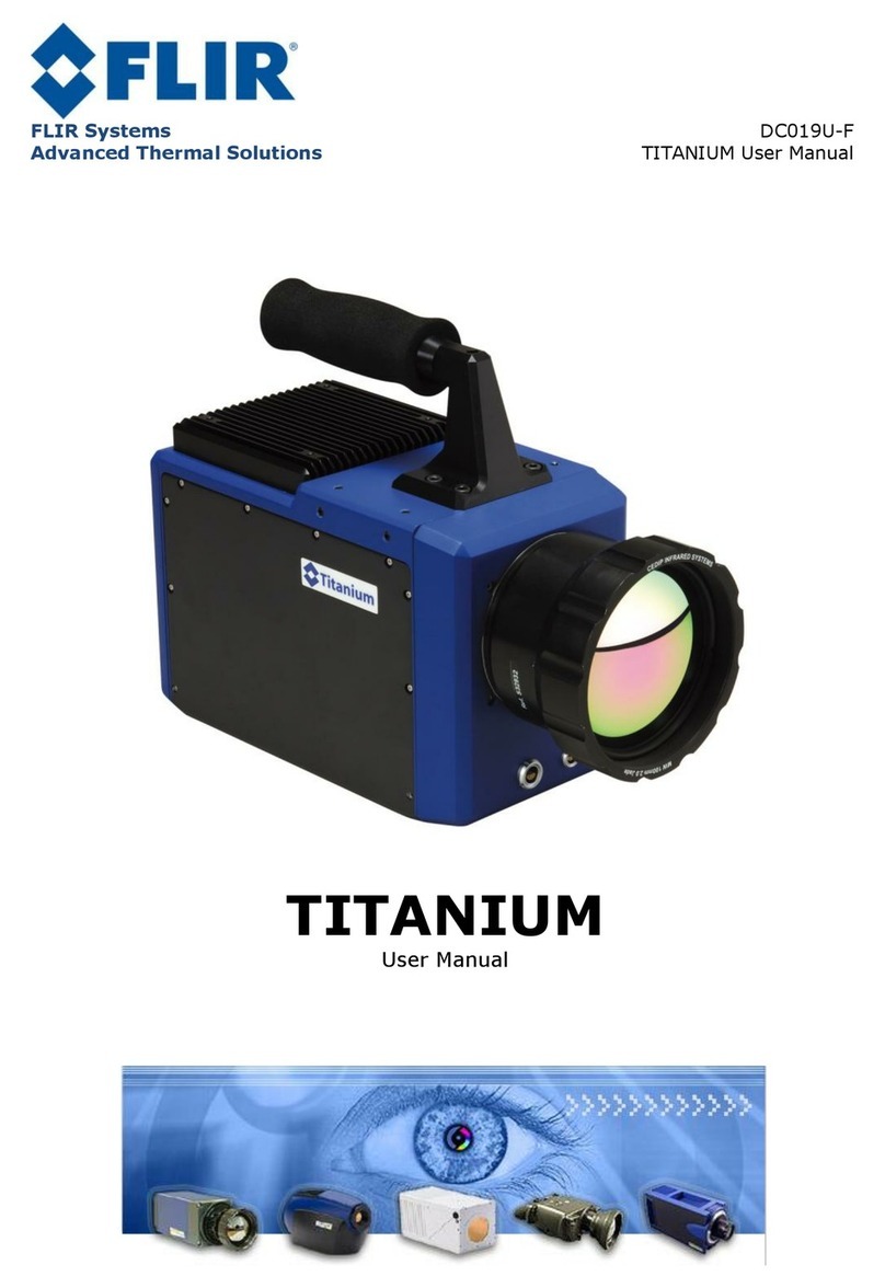
FLIR SC2500 User manual

Advanced Thermal Solutions
DCO65U-E
SC2500 User Manual
SC2500
User Manual

Advanced Thermal Solutions SC2500 User Manual
DCO65U-E SC2500 User Manual Page 2
PAGE LEFT INTENTIONNALY BLANK

Advanced Thermal Solutions SC2500 User Manual
DCO65U-E SC2500 User Manual Page 3
1. Contents
1. Contents ..............................................................................................3
2. For your safety.....................................................................................4
3. Precautions..........................................................................................6
4. General Overview.................................................................................7
4.1. Product Overview ............................................................................................ 7
4.2. Packing Contents ............................................................................................ 7
4.3. Camera description ......................................................................................... 9
5. Starting with the camera ...................................................................11
5.1. Mounting the camera..................................................................................... 11
5.2. Installation of the software on the computer..................................................... 11
5.3. Connecting the camera .................................................................................. 11
5.4. Powering the camera ..................................................................................... 11
5.5. Pointing and focusing..................................................................................... 12
5.6. Camera Power Off ......................................................................................... 12
5.7. Precautions .................................................................................................. 12
5.8. Training ....................................................................................................... 12
6. Using your camera .............................................................................13
6.1. Changing the lens ......................................................................................... 13
6.2. Removing the lens interface ........................................................................... 13
6.3. Change of filter holder ................................................................................... 14
6.4. Change of filter ............................................................................................. 14
6.5. Lock-In connection ........................................................................................ 16
6.6. Special features ............................................................................................ 17
6.7. How to NUC.................................................................................................. 20
6.8. Temperature Calibration ................................................................................ 25
7. Maintenance ......................................................................................26
7.1. Cleaning optical surfaces................................................................................ 26
7.2. Storing ........................................................................................................ 26
8. Accessories ........................................................................................27
8.1. Additional lenses ........................................................................................... 27
8.2. Tripods / pan & tilt ........................................................................................ 27
8.3. Filters .......................................................................................................... 27
9. Diagnostics ........................................................................................28
9.1. Diagnostic table ............................................................................................ 28
9.1. How to contact after sale service? ................................................................... 31
10. Technical data....................................................................................33
10.1.Characteristics .............................................................................................. 33
10.2.Typical InGaAs vs VisGaAs Spectral Quantum Efficiency ..................................... 34
10.3.Mechanical Interface...................................................................................... 35
10.4.Electrical interface ......................................................................................... 36
Advanced Thermal Solutions SC2500 User Manual
DCO65U-E SC2500 User Manual Page 4
2. For your safety
To ensure no damage to your FLIR Systems equipment, you or other people,
carefully read the following recommendations before using your equipment.
Then keep these instructions in a place easily accessible to all those which will
have to use this camera
The importance of the consequences due to the non-observance of these
instructions is highlighted in the following way:
This icon announces the instructions which MUST be read before
using your FLIR Systems equipment to avoid possible physical
risks.
In the event of dysfunction
of your equipment, stop it
immediately
If you notice smoke or an
unusual odor releasing itself
from your camera or the adapter
sector, disconnect the adapter
sector immediately, taking care
not to burn yourself. To continue
using the equipment in this case
can be dangerous. Immediately
contact FLIR Systems to check.
Do not use your equipment in
aflammable gas environ-
ment
Do not use electronic material in
the presence of flammable gas
because that is likely to cause
an explosion or a fire.
Do not dismount your
material
Touching internal parts of the
camera can be extremely
dangerous. If your camera does
not properly work, it must be
repaired by a qualified
technician.
If your camera opens due to a
fall or any other accident,
unplug the power adaptor and
immediately contact FLIR
Systems.
Use appropriate cables.
Only use dedicated cable
delivered by FLIR Systems to
maintain conformity with your
camera specifications.

Advanced Thermal Solutions SC2500 User Manual
DCO65U-E SC2500 User Manual Page 5
CD-ROM
CD containing software and
manuals must not be placed in
audio CD players. Reading it can
cause audition loss or damage
the equipment.
Camera temperature
Depending on climatic
conditions, the camera surfaces
can be hot. Take care when
holding the camera.

Advanced Thermal Solutions SC2500 User Manual
DCO65U-E SC2500 User Manual Page 6
3. Precautions
To maximize the lifetime and get the best use of your FLIR Systems
equipment, observe the following instructions when storing or using it.
Keep it dry
This device will be damaged if
immerged in water or exposed
to high temperatures.
Do not exceed the specified
environmental conditions.
Your equipment may not
function correctly after being
subjected to extreme
environmental conditions
Handle with great care the
lenses and all moving parts.
Avoid abrupt changes of
temperature
Abrupt changes of temperature,
for example, if you enter a
heated place in cold weather
conditions, can cause
condensation inside the device.
Do not drop your camera
The camera may not function
correctly after being subjected
to violent shocks or strong
vibrations.
Handle the objective gently, as
well as connectors. These parts
are particularly fragile.

Advanced Thermal Solutions SC2500 User Manual
DCO65U-E SC2500 User Manual Page 7
4. General Overview
4.1. Product Overview
The SC2500 complements FLIR’s range of products for R&D and automation
applications. It embeds a French InGaAs detector with a spectral sensitivity
from 0.9 to 1.7µm (SC2500N).
The SC2500 can also be delivered with a VisGaAs detector, which allows an
extended spectral sensitivity into the visible range with a spectral range of 0.4
to 1.7 µm (SC2500VN).
Its removable lens interface makes it easy to integrate with custom devices or
spectrometers, while a Gigabit Ethernet digital interface ensures a seamless
connection to standard PC and laptops. It features a Trigger input/ouptut
allowing synchronization with the most fleeting event, as well as a Lock-In
input used to enhance signal-to-noise ratio imaging, based on an image
correlation process.
The camera embeds all necessary images processing in order to deliver ready
to use, sharp images for applications such as silicon wafer or solar cells
inspection, laser profiling, paint analysis, water or ice detection, imaging
spectroscopy or high temperature thermography.
4.2. Packing Contents
The camera is delivered in a robust transport case.

Advanced Thermal Solutions SC2500 User Manual
DCO65U-E SC2500 User Manual Page 8
1 SC2500 Camera
1 Power supply with power Cord
1 Ethernet Cable
1 Lock-In Cable
1 Trigger Cable
1 Analog Video Cable
1 Waterproof case
Optical cleaning tissue
1 CD ROM containing software and camera files
1 Camera User Manual
1 Camera Characterization file
Optional :
1 or more additional lenses (Optional)
1 Tripod (Optional)

Advanced Thermal Solutions SC2500 User Manual
DCO65U-E SC2500 User Manual Page 9
4.3. Camera description
Giga Ethernet Connector
Filter Holder
Analog Video Connector
On/Off button
Power In Connector
Trigger Connector
Lockin Connector

Advanced Thermal Solutions SC2500 User Manual
DCO65U-E SC2500 User Manual Page 10
Tripod Thread
Thread for fixing on a plate
Camera with front plate removed
Detector housing

Advanced Thermal Solutions SC2500 User Manual
DCO65U-E SC2500 User Manual Page 11
5. Starting with the camera
This part explains in detail all steps to be followed before using your camera for
the first time.
5.1. Mounting the camera
Ensure you that the camera is posed on a stable surface or correctly screwed
on the tripod.
5.2. Installation of the software on the computer
Software is pre installed on the computer
See software manual for installation instruction
Install frame grabber drivers, VirCAM acquisition drivers, Camera Command
software CIRRUS & Altair software.
5.3. Connecting the camera
Connect the power cable on connector with the red reference mark.
Connect the Ethernet cable between the camera and the computer.
If required connect the camera to a video monitor in order to control the
image. Use a cable BNC 75 ohms or S-video which you will connect to the
camera by using the video adapter provided with the camera (blue reference
mark)
5.4. Powering the camera
The camera is turned on by pressing the ON/OFF button. After a few seconds,
3s typically, the system displays a pattern on the video output.
Figure 1 : Pattern
It is necessary to wait about one minute so that the camera is ready to take
infrared images. The pattern is displayed during all this time.
The camera is turned off by pressing the ON/OFF button.

Advanced Thermal Solutions SC2500 User Manual
DCO65U-E SC2500 User Manual Page 12
5.5. Pointing and focusing
Before taking a measurement, ensure that the object is located at the center of
the image and that focusing is optimized.
The installation of a filter in the optical path modifies the
focusing distance.
Refocus after positioning a filter.
5.6. Camera Power Off
The camera is turned off by pressing the ON/OFF button.
5.7. Precautions
Do not exceed specified environmental conditions.
Your equipment risks malfunction after being exposed to extreme
environmental conditions.
Handle with great care the lens and all moving parts
Handle gently any additional lenses, as well as the connectors. These
parts are particularly fragile.
Connection of cables
The connection and disconnection of the cables can be carried out at any
time, camera on or off, computer on or off.
5.8. Training
This equipment and its use require knowledge of the field of infrared
thermography in order to make best use of the camera and the processing of
acquisitions.
FLIR Systems offers training schemes allowing you to use this equipment to its
full potential. You can contact FLIR Systems in order to establish your training
requirements.

Advanced Thermal Solutions SC2500 User Manual
DCO65U-E SC2500 User Manual Page 13
6. Using your camera
6.1. Changing the lens
Lenses are fragile elements.
Take the greatest care at the time of their handling, particularly on
the level of the lenses.
Lenses can be heavy.
Some lenses weight several hundred grams. Be careful not to be
surprised by its weight.
Lenses are mounted on a C-Mount interface.
Turn the optic counter-clockwise while placing a hand below. It may be
necessary to do some turns.
Place caps on the lens and store it.
Never force on lens.
Check that optics is clean before assembling it in the camera. See
section 7.1 for the maintenance of optics
Remove the caps of the lenses that you wish to use and place it gently into
the thread. Gently insert the lens and turn it clockwise.
6.2. Removing the lens interface
The lens interface of the camera, which also holds the filter wheel
mechanism, can be removed so a custom lens interface can be installed.
Unscrew the four screws located around the C-Mount thread using the
appropriate 2 mm TORX screwdriver.

Advanced Thermal Solutions SC2500 User Manual
DCO65U-E SC2500 User Manual Page 14
6.3. Change of filter holder
The filters are extremely fragile elements
Take great care when handling them. Use rubber fingers protection
and optical tissue for handling filters.
Prepare the necessary equipment.
See cleaning optics chapter (cf. §7.1).
Check that filters are clean.
See chapter 7.1 for cleaning instructions. Any finger mark must be
cleaned immediately.
Pull out the filter holder vertically. Place back the filter holder in the
opposite direction.
6.4. Change of filter
1. Remove the filter holder from the camera
2. Remove the stops and the slot ring (holding the filter) with a 2.0mm
flat head screwdriver and remove carefully the filter in place

Advanced Thermal Solutions SC2500 User Manual
DCO65U-E SC2500 User Manual Page 15
3. Place the new IR filter. An IR filter has different coatings on each side
(usually a metallic reflective layer and a colored or opaque layer): the
metallic layer side needs to be placed towards the radiation source.
Place the filter as recommended in the slot and secure it with the
safety ring,
4. Place the slot ring carefully and tighten it gently.
Note: there is enough depth (2.3 mm available) for two filters in one slot (if
needed). In this case, a different spacer ring is inserted between the two
filters.
Slot ring
Spacer ring
Filter

Advanced Thermal Solutions SC2500 User Manual
DCO65U-E SC2500 User Manual Page 16
6.5. Lock-In connection
To use the Lock-In option, you need an X0914 cable linked to the SC2500
Lock-In connector.
Lock-In
Input Range 0-10V peak to peak / 1Hz up to 5 kHz
Connect the Lock-In connector’s input to your signal generator source. Detailed
use of Lock-In can be found in ALTAIR’s or TheSA’s manual.
Input
To Camera

Advanced Thermal Solutions SC2500 User Manual
DCO65U-E SC2500 User Manual Page 17
6.6. Special features
The following special features can be selected using the SC2500 Specific
parameters window (ALTAIR Camera Tab Advanced).
Gain
The SC2500 camera has two gain modes:
-High gain mode 0.17 Me- Well Capacity
-Low gain mode 3.5 Me- Well Capacity
The high gain mode will be used when the application is photon starved
and a high-sensitivity is required.
The low gain mode will be used when the application is photon-shot-noise
limited and a high signal-to-noise ratio is required.

Advanced Thermal Solutions SC2500 User Manual
DCO65U-E SC2500 User Manual Page 18
Integration modes
The SC2500 camera integration time range goes
from 400 ns up to 1 s. Standard operating mode
- ITR or IWR - can handle integration time values
from 6 µs up to 999 ms. To be able to use the
camera between 400 ns and 5 µs, you’ll have to
select the ShortITR mode.
TEC Module (Thermo-Electric Cooling Module)
The SC2500 detector’s is fitted with a TEC-1 (one stage thermo-electric
cooling module). The TEC is used to stabilize the detector when the
application requires a stabilized output vs. camera’s internal temperature
variation (high temperature thermography and general radiance
metrology).
Image quality can also be optimized by adjusting the TEC set point to the
FPA temperature at which the NUC has been done.
TEC is ON FPA Temperature
is a the user defined set point
TEC is OFF FPA Temperature is consistent
with internal camera’s temperature

Advanced Thermal Solutions SC2500 User Manual
DCO65U-E SC2500 User Manual Page 19
How to define the set point value?
For best performances, we recommend you to choose a FPA Temperature
Set Point included in the following range: [Tcam –20 °C; Tcam], Tcam
being the internal camera temperature as read at the bottom of ALTAIR’s
window.
If the camera’s internal temperature gets too high and makes your set
point to be out of the recommended range, you’ll have to manually
adjust the set point as described above.
Your SC2500 camera is delivered with several presets made with a
TEC set point of 35°C.

Advanced Thermal Solutions SC2500 User Manual
DCO65U-E SC2500 User Manual Page 20
6.7. How to NUC
The NUC procedure document (ref. DP001U) can be found on the CD-ROM
that is shipped with the camera. This document contains important
information on why and how to perform a NUC correction.
The main difference between performing a NUC on a NIR camera and a
MW/LW IR camera lies in the light source to be considered. Typical light
sources in the Near/Short-Infrared are Integrating Spheres. An Integrating
Sphere is an optical device consisting of a hollow cavity with its interior
coated for reflectivity optimization. The relevant point is that the light
emitted by the sphere presents a high uniformity level.
The information found below is a quick tutorial on how to NUC your SC2500
camera. It is not meant to replace the DP001U-NUC Procedure document
which deals extensively with the NUC process.
Here are the basic steps to perform a NUC:
-Set-up the camera :
a. Mount any optical device needed (lens, filter),
b. Choose the proper iris aperture (f/#) on the lens (if any)
and focus the lens at a distant object,
c. Choose the proper gain level (High/Low) adapted to your
application,
d. Choose the proper Integration time adapted to your
application.
-A NUC operation is performed by placing the camera in front of a
light source at two different flux output levels, using the software
tools provided by FLIR: ALTAIR & CIRRUS Software.
Table of contents
Other FLIR Thermal Camera manuals

FLIR
FLIR BHS-Series User manual

FLIR
FLIR FLIR TG167 User manual

FLIR
FLIR TruWITNESS User manual

FLIR
FLIR K Series User manual

FLIR
FLIR T6 series User manual

FLIR
FLIR TG267 User manual

FLIR
FLIR ThermaCAM SC640 User manual

FLIR
FLIR T600 User manual

FLIR
FLIR Voyager III User manual

FLIR
FLIR T6 series User manual

FLIR
FLIR T4 Series User manual

FLIR
FLIR CX series User manual

FLIR
FLIR FC-Series User manual

FLIR
FLIR PathFindIR User manual

FLIR
FLIR FLIR H Series User manual

FLIR
FLIR PatrolIR PTZ User manual

FLIR
FLIR FC-Series S User manual

FLIR
FLIR Voyager User manual

FLIR
FLIR A310 ex Series User manual

FLIR
FLIR Duo Pro R Operating and maintenance instructions