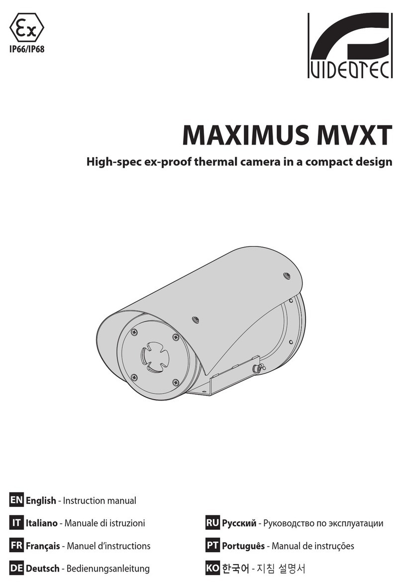
FLIR A310 ex Series User manual

User’s manual
FLIR A310 ex
nbn Austria GmbH


User’s manual
FLIR A310 ex
#T559891; r. AE/57789/57789; en-US iii


Table of contents
1 Disclaimers ......................................................................................1
1.1 Legal disclaimer .......................................................................1
1.2 Usage statistics ........................................................................ 1
1.3 U.S. Government Regulations...................................................... 1
1.4 Copyright ................................................................................1
1.5 Quality assurance .....................................................................1
1.6 Patents...................................................................................1
1.7 EULATerms ............................................................................1
1.8 EULATerms ............................................................................1
2 Safety information .............................................................................2
3 Notice to user ...................................................................................3
3.1 Calibration...............................................................................3
3.2 Accuracy ................................................................................3
3.3 Disposal of electronic waste ........................................................3
3.4 Training ..................................................................................3
3.5 Documentation updates ............................................................. 3
3.6 Important note about this manual.................................................. 4
3.7 Note about authoritative versions..................................................4
4 Customer help ..................................................................................5
4.1 General ..................................................................................5
4.2 Submitting a question ................................................................ 5
4.3 Downloads ..............................................................................5
5 What is FLIR A310 ex?........................................................................6
6 Typical system overview.....................................................................7
7 Typical system setup procedure..........................................................8
8 Technical data...................................................................................9
8.1 Online field-of-view calculator ...................................................... 9
8.2 Note about technical data ...........................................................9
8.3 Note about authoritative versions..................................................9
8.4 FLIR A310 ex 25°.................................................................... 10
8.5 FLIR A310 ex 45°.................................................................... 14
9 Mechanical drawings ....................................................................... 18
10 EC Type Examination Certificate........................................................ 20
11 EC Type Examination Certificate, 1st supplement................................ 23
12 EC Type Examination Certificate, 2nd supplement............................... 26
13 EC Type Examination Certificate, 3rd supplement ............................... 28
14 EC Declaration of conformity (enclosure)........................................... 31
15 Certiticate of conformity (camera) ..................................................... 33
16 Thermographic measurement techniques .......................................... 35
16.1 Introduction .......................................................................... 35
16.2 Emissivity.............................................................................. 35
16.2.1 Finding the emissivity of a sample .................................... 35
16.3 Reflected apparent temperature................................................. 39
16.4 Distance ............................................................................... 39
16.5 Relative humidity .................................................................... 39
16.6 Other parameters.................................................................... 39
17 About FLIR Systems ........................................................................ 40
17.1 More than just an infrared camera .............................................. 41
17.2 Sharing our knowledge ............................................................ 41
17.3 Supporting our customers......................................................... 42
A OEM manual (German)..................................................................... 43
B OEM manual (English) ..................................................................... 67
#T559891; r. AE/57789/57789; en-US v


Disclaimers
1
1.1 Legal disclaimer
For warranty terms, please refer to https://www.flir.com/warranty.
1.2 Usage statistics
FLIR Systems reserves the right to gather anonymous usage statistics to help
maintain and improve the quality of our software and services.
1.3 U.S. Government Regulations
This product may be subject to U.S. Export Regulations. Please send any in-
1.4 Copyright
© 2019, FLIR Systems, Inc. All rights reserved worldwide. No parts of the
software including source code may be reproduced, transmitted, transcribed
or translated into any language or computer language in any form or by any
means, electronic, magnetic, optical, manual or otherwise, without the prior
written permission of FLIR Systems.
The documentation must not, in whole or part, be copied, photocopied, re-
produced, translated or transmitted to any electronic medium or machine
readable form without prior consent, in writing, from FLIR Systems.
Names and marks appearing on the products herein are either registered
trademarks or trademarks of FLIR Systems and/or its subsidiaries. All other
trademarks, trade names or company names referenced herein are used for
identification only and are the property of their respective owners.
1.5 Quality assurance
The Quality Management System under which these products are developed
and manufactured has been certified in accordance with the ISO 9001
standard.
FLIR Systems is committed to a policy of continuous development; therefore
we reserve the right to make changes and improvements on any of the prod-
ucts without prior notice.
1.6 Patents
This product is protected by patents, design patents, patents pending, or de-
sign patents pending. Please refer to the FLIR Systems’ patent registry:
https://www.flir.com/patentnotices.
1.7 EULA Terms
Qt4 Core and Qt4 GUI, Copyright ©2013 Nokia Corporation and FLIR Sys-
tems AB. This Qt library is a free software; you can redistribute it and/or mod-
ify it under the terms of the GNU Lesser General Public License as published
by the Free Software Foundation; either version 2.1 of the License, or (at your
option) any later version. This library is distributed in the hope that it will be
useful, but WITHOUT ANY WARRANTY; without even the implied warranty of
MERCHANTABILITY or FITNESS FOR A PARTICULAR PURPOSE. See the
GNU Lesser General Public License, http://www.gnu.org/licenses/lgpl-2.1.
html. The source code for the libraries Qt4 Core and Qt4 GUI may be re-
quested from FLIR Systems AB.
1.8 EULA Terms
• You have acquired a device (“INFRARED CAMERA”) that includes soft-
ware licensed by FLIR Systems AB from Microsoft Licensing, GP or its
affiliates (“MS”). Those installed software products of MS origin, as well
as associated media, printed materials, and “online” or electronic docu-
mentation (“SOFTWARE”) are protected by international intellectual
property laws and treaties. The SOFTWARE is licensed, not sold. All
rights reserved.
• IF YOU DO NOT AGREE TO THIS END USER LICENSE AGREEMENT
(“EULA”), DO NOT USE THE DEVICE OR COPY THE SOFTWARE. IN-
STEAD, PROMPTLY CONTACT FLIR Systems AB FOR INSTRUC-
TIONS ON RETURN OF THE UNUSED DEVICE(S) FOR A REFUND.
ANY USE OF THE SOFTWARE, INCLUDING BUT NOT LIMITED TO
USE ON THE DEVICE, WILL CONSTITUTE YOUR AGREEMENT TO
THIS EULA (OR RATIFICATION OF ANY PREVIOUS CONSENT).
•GRANT OF SOFTWARE LICENSE. This EULA grants you the following
license:
◦ You may use the SOFTWARE only on the DEVICE.
◦NOT FAULT TOLERANT. THE SOFTWARE IS NOT FAULT TOL-
ERANT. FLIR Systems AB HAS INDEPENDENTLY DETERMINED
HOW TO USE THE SOFTWARE IN THE DEVICE, AND MS HAS
RELIED UPON FLIR Systems AB TO CONDUCT SUFFICIENT
TESTING TO DETERMINE THAT THE SOFTWARE IS SUITABLE
FOR SUCH USE.
◦NO WARRANTIES FOR THE SOFTWARE. THE SOFTWARE is
provided “AS IS” and with all faults. THE ENTIRE RISK AS TO
SATISFACTORY QUALITY, PERFORMANCE, ACCURACY, AND
EFFORT (INCLUDING LACK OF NEGLIGENCE) IS WITH YOU.
ALSO, THERE IS NO WARRANTY AGAINST INTERFERENCE
WITH YOUR ENJOYMENT OF THE SOFTWARE OR AGAINST
INFRINGEMENT. IF YOU HAVE RECEIVED ANY WARRANTIES
REGARDING THE DEVICE OR THE SOFTWARE, THOSE WAR-
RANTIES DO NOT ORIGINATE FROM, AND ARE NOT BINDING
ON, MS.
◦ No Liability for Certain Damages. EXCEPT AS PROHIBITED BY
LAW, MS SHALL HAVE NO LIABILITY FOR ANY INDIRECT,
SPECIAL, CONSEQUENTIAL OR INCIDENTAL DAMAGES
ARISING FROM OR IN CONNECTION WITH THE USE OR PER-
FORMANCE OF THE SOFTWARE. THIS LIMITATION SHALL
APPLY EVEN IF ANY REMEDY FAILS OF ITS ESSENTIAL PUR-
POSE. IN NO EVENT SHALL MS BE LIABLE FOR ANY
AMOUNT IN EXCESS OF U.S. TWO HUNDRED FIFTY DOL-
LARS (U.S.$250.00).
◦Limitations on Reverse Engineering, Decompilation, and Dis-
assembly. You may not reverse engineer, decompile, or disas-
semble the SOFTWARE, except and only to the extent that such
activity is expressly permitted by applicable law notwithstanding
this limitation.
◦SOFTWARE TRANSFER ALLOWED BUT WITH RESTRIC-
TIONS. You may permanently transfer rights under this EULA only
as part of a permanent sale or transfer of the Device, and only if
the recipient agrees to this EULA. If the SOFTWARE is an upgrade,
any transfer must also include all prior versions of the SOFTWARE.
◦EXPORT RESTRICTIONS. You acknowledge that SOFTWARE is
subject to U.S. export jurisdiction. You agree to comply with all ap-
plicable international and national laws that apply to the SOFT-
WARE, including the U.S. Export Administration Regulations, as
well as end-user, end-use and destination restrictions issued by U.
S. and other governments. For additional information see http://
www.microsoft.com/exporting/.
#T559891; r. AE/57789/57789; en-US 1
Safety information
2
CAUTION
Do not point the infrared camera (with or without the lens cover) at strong energy sources, for example,
devices that cause laser radiation, or the sun. This can have an unwanted effect on the accuracy of the
camera. It can also cause damage to the detector in the camera.
CAUTION
Applicability: Cameras with an automatic shutter that can be disabled.
Do not disable the automatic shutter in the camera for a long time period (a maximum of 30 minutes is
typical). If you disable the shutter for a longer time period, damage to the detector can occur.
#T559891; r. AE/57789/57789; en-US 2

Notice to user
3
3.1 Calibration
We recommend that you send in the camera for calibration once a year. Contact your lo-
cal sales office for instructions on where to send the camera.
3.2 Accuracy
For very accurate results, we recommend that you wait 5 minutes after you have started
the camera before measuring a temperature.
3.3 Disposal of electronic waste
Electrical and electronic equipment (EEE) contains materials, components and substan-
ces that may be hazardous and present a risk to human health and the environment
when waste electrical and electronic equipment (WEEE) is not handled correctly.
Equipment marked with the below crossed-out wheeled bin is electrical and electronic
equipment. The crossed-out wheeled bin symbol indicates that waste electrical and elec-
tronic equipment should not be discarded together with unseparated household waste,
but must be collected separately.
For this purpose all local authorities have established collection schemes under which
residents can dispose waste electrical and electronic equipment at a recycling centre or
other collection points, or WEEE will be collected directly from households. More de-
tailed information is available from the technical administration of the relevant local
authority.
3.4 Training
To read about infrared training, visit:
• http://www.infraredtraining.com
• http://www.irtraining.com
• http://www.irtraining.eu
3.5 Documentation updates
Our manuals are updated several times per year, and we also issue product-critical notifi-
cations of changes on a regular basis.
To access the latest manuals, translations of manuals, and notifications, go to the Down-
load tab at:
http://support.flir.com
It only takes a few minutes to register online. In the download area you will also find the
latest releases of manuals for our other products, as well as manuals for our historical
and obsolete products.
#T559891; r. AE/57789/57789; en-US 3

Notice to user3
3.6 Important note about this manual
FLIR Systems issues generic manuals that cover several cameras within a model line.
This means that this manual may contain descriptions and explanations that do not apply
to your particular camera model.
3.7 Note about authoritative versions
The authoritative version of this publication is English. In the event of divergences due to
translation errors, the English text has precedence.
Any late changes are first implemented in English.
#T559891; r. AE/57789/57789; en-US 4

Customer help
4
4.1 General
For customer help, visit:
http://support.flir.com
4.2 Submitting a question
To submit a question to the customer help team, you must be a registered user. It only
takes a few minutes to register online. If you only want to search the knowledgebase for
existing questions and answers, you do not need to be a registered user.
When you want to submit a question, make sure that you have the following information
to hand:
• The camera model
• The camera serial number
• The communication protocol, or method, between the camera and your device (for ex-
ample, SD card reader, HDMI, Ethernet, USB, or FireWire)
• Device type (PC/Mac/iPhone/iPad/Android device, etc.)
• Version of any programs from FLIR Systems
• Full name, publication number, and revision number of the manual
4.3 Downloads
On the customer help site you can also download the following, when applicable for the
product:
• Firmware updates for your infrared camera.
• Program updates for your PC/Mac software.
• Freeware and evaluation versions of PC/Mac software.
• User documentation for current, obsolete, and historical products.
• Mechanical drawings (in *.dxf and *.pdf format).
• Cad data models (in *.stp format).
• Application stories.
• Technical datasheets.
#T559891; r. AE/57789/57789; en-US 5

What is FLIR A310 ex?
5
Explosive atmospheres need to be protected from ignition sources by selecting equip-
ment and protective systems that meet the requirements of the ATEX product directives
and similar regulations.
The FLIR A310 ex is an ATEX-proof solution, with a thermal imaging camera mounted in
an enclosure, making it possible to monitor critical and other valuable assets in explosive
atmospheres. Process monitoring, quality control, and fire detection in potentially explo-
sive locations are typical applications for the FLIR A310 ex.
Key features:
• Thermography monitoring and early fire detection in explosion hazard areas.
• Enclosures for infrared cameras in classification zones 1, 2, 21, and 22.
• ATEX certified to the latest standards.
• Rated to protection class IP67.
• Plug and play installation, with the enclosure delivered ready for use.
#T559891; r. AE/57789/57789; en-US 6

Typical system overview
6
1. Thermovision System Tools & Utilities CD-ROM.
2. Ethernet cable.1
3. Optical-to-Ethernet converter.1
4. FC connectors from the camera housing (including two spares).
5. 24 V DC power supply.1
6. Pigtail cable from the housing. The color coding of the pigtail cable is:
• Brown: positive (+).
• Blue: negative (–).
• Green/yellow: earth.
#T559891; r. AE/57789/57789; en-US 7
1. Not supplied with the camera unit.

Typical system setup procedure
7
1. Unpack the camera unit from the cardboard box.
2. Install the camera unit at the intended location. It is the responsibility of the installer
to meet all applicable safety standards required by the authorities of the region in
which the unit will be operating in.
3. Connect the camera unit to an external power supply.2The unit requires 24 V DC in.
The color coding of the pigtail cable is:
• Brown: positive +.
• Blue: negative –.
• Green/yellow: earth.
Note The external power supply must not be inside the classified zone.
4. Connect the camera unit to an optical-to-Ethernet converter.2
Note The optical-to-Ethernet converter must not be inside the classified zone.
5. Install the Thermovision System Tools & Utilities CD-ROM on a computer connected
to the network. This will install the following software:
• FLIR IP Config.
• FLIR IR Monitor.
• FLIR IR Camera Player.
6. Start FLIR IP Config to identify the unit in the network and automatically assign or
manually set IP addresses, etc. For more information, see the FLIR IP Config manual
on the User Documentation CD-ROM or on the Help menu in FLIR IP Config.
7. Start FLIR IR Monitor to control the camera, e.g., laying out measurement tools and
setting up alarms. For more information, see the FLIR IR Monitor manual on the User
Documentation CD-ROM or on the Help menu in FLIR IR Monitor.
#T559891; r. AE/57789/57789; en-US 8
2. Not supplied with the camera unit.

Technical data
8
Table of contents
8.1 Online field-of-view calculator.............................................................9
8.2 Note about technical data...................................................................9
8.3 Note about authoritative versions........................................................9
8.4 FLIR A310 ex 25° ............................................................................. 10
8.5 FLIR A310 ex 45° ............................................................................. 14
8.1 Online field-of-view calculator
Please visit http://support.flir.com and click the photo of the camera series for field-of-
view tables for all lens–camera combinations.
8.2 Note about technical data
FLIR Systems reserves the right to change specifications at any time without prior notice.
Please check http://support.flir.com for latest changes.
8.3 Note about authoritative versions
The authoritative version of this publication is English. In the event of divergences due to
translation errors, the English text has precedence.
Any late changes are first implemented in English.
#T559891; r. AE/57789/57789; en-US 9

Technical data8
8.4 FLIR A310 ex 25°
P/N: 71001-1103
Rev.: 51350
Introduction
The FLIR A310 ex is an ATEX-proof solution, with a thermal imaging camera mounted in
an enclosure—making it possible to monitor critical and other valuable assets in explo-
sive atmospheres. Process monitoring, quality control, and fire detection in potentially
explosive locations are typical applications for the FLIR A310 ex.
• Thermographic monitoring and early fire detection in an explosion–hazard area.
• Enclosures for infrared cameras in Ex zones 1, 2, 21, 22.
• ATEX certified.
• Protection class IP67.
• Plug-and-play installation with the enclosure delivered ready for use.
• Available with additional options.
The certification covers the entire system, which includes the enclosure as well as all
components inside of it, such as the infrared camera, heater, and integrated controller.
This means that no additional certification is required for operation.
The integrated controller is equipped with two fiber optic and two Ethernet ports. This en-
ables a flexible network integration in star ring topologies.
In addition, the integrated controller features several digital I/O channels and sensors for
temperature, humidity, and pressure. Among other functions, the I/O channels enable
the user to switch on/off the camera and the heater via remote control. Access is through
an integrated web interface or Modbus TCP/IP.
Explosion-proof housing
General data
Ambient temperature range for operation –40°C to +60°C (–40°F to +140°F)
Protection class IP67
Weight 6.7 kg (without camera and lens)
Empty volume 5.06 l
External dimensions (without sun shield) D = 170 mm, L = 408 mm
Housing material Nickel-plated aluminium
Surface Powder coated
Protection window Germanium, double-sided AR Coated, externally
with additional hard-carbon layer
Maximum power of the additional heater 16 W
Operating voltage 24 V DC
Maximum electric connection power 60 W
Power cable Helukabel 37264
Length of power cable 4 m (13 ft.)
Power cable configuration Pigtail
Ethernet medium Multi-mode breakout fiber AT-V(ZN)Y(ZN)Y 4G50/
125 OM2
Length of Ethernet cable 4 m (13 ft.)
Ethernet configuration Pigtail with FC connector
#T559891; r. AE/57789/57789; en-US 10

Technical data8
Explosion protection-specific data
For use in EX zone 1, 2, 21, 22
Ignition protection category Flame-proof enclosure “d”
Maximum surface temperature (according to tem-
perature class T6)
Maximum 85°C
ATEX certification (version -AXC) • II 2G Ex db IIC T6 / T5
• II 2D Ex tb IIIC T85° / T100
Verification certificate ZELM 12 ATEX 0485 X
Camera system
Imaging and optical data
IR resolution 320 × 240 pixels
Thermal sensitivity/NETD < 0.05°C @ +30°C (+86°F) / 50 mK
Field of view (FOV) 25° × 18.8°
Minimum focus distance 0.4 m (1.31 ft.)
Focal length 18 mm (0.7 in.)
Spatial resolution (IFOV) 1.36 mrad
Lens identification Automatic
F-number 1.3
Image frequency 30 Hz
Focus Automatic or manual (built in motor)
Zoom 1–8× continuous, digital, interpolating zooming on
images
Detector data
Detector type Focal plane array (FPA), uncooled
microbolometer
Spectral range 7.5–13 µm
Detector pitch 25 µm
Detector time constant Typical 12 ms
Measurement
Object temperature range • –20 to +120°C (–4 to +248°F)
• 0 to +350°C (+32 to +662°F)
Accuracy ±4°C (±7.2°F) or ±4% of reading
Measurement analysis
Spotmeter 10 (with no image streaming)
Area 10 boxes with max./min./average/position (with no
image streaming)
Isotherm 1 with above/below/interval
Measurement option Measurement Mask Filter
Schedule response: File sending (ftp), email
(SMTP)
Difference temperature Delta temperature between measurement func-
tions or reference temperature
Reference temperature Manually set or captured from any measurement
function
Atmospheric transmission correction Automatic, based on inputs for distance, atmos-
pheric temperature and relative humidity
Optics transmission correction Automatic, based on signals from internal sensors
#T559891; r. AE/57789/57789; en-US 11
Technical data8
Measurement analysis
Emissivity correction Variable from 0.01 to 1.0
Reflected apparent temperature correction Automatic, based on input of reflected
temperature
External optics/windows correction Automatic, based on input of optics/window trans-
mission and temperature
Measurement corrections Global and individual object parameters
Alarm
Alarm functions 6 automatic alarms on any selected measurement
function, Digital In, Camera temperature, timer
Alarm output Log, store image, file sending (ftp), email notifica-
tion (SMTP).
With an additional FLIR I/O module (T130090 or
T130091), the system can provide up to 8 digital
outputs and 8 analog outputs that can be con-
nected to any camera analytic function or the
cameras status. These outputs can be connected
to existing alarm infrastructure, PLCs, or data
loggers.
Set-up
Color palettes Color palettes (BW, BW inv, Iron, Rain)
Set-up commands Date/time, Temperature (°C/°F)
Storage of images
Storage media Built-in memory for image storage
File formats Standard JPEG, 16-bit measurement data
included
Ethernet
Ethernet Control, result and image
Ethernet, type 100 Mbps
Ethernet, standard IEEE 802.3
Ethernet, configuration Pigtail with FC-connector (fiber)
Ethernet, communication TCP/IP socket-based FLIR proprietary
Ethernet, video streaming MPEG-4, ISO/IEC 14496-1 MPEG-4 ASP@L5
Ethernet, image streaming 16-bit 320 × 240 pixels @ 7-8 Hz
• Radiometric
Ethernet, protocols Ethernet/IP, Modbus TCP, TCP, UDP, SNTP, RTSP,
RTP, HTTP, ICMP, IGMP, ftp, SMTP, SMB (CIFS),
DHCP, MDNS (Bonjour), uPnP
Shipping information
Packaging, type Cardboard box
List of contents • Infrared camera with lens, in explosion-proof
housing
• Printed documentation
• Utility CD-ROM
Packaging, weight
Packaging, size 495 × 370 × 192 mm (19.5 × 14.6 × 7.6 in.)
EAN-13 7332558008355
UPC-12 845188008703
Country of origin Sweden
#T559891; r. AE/57789/57789; en-US 12

Technical data8
Supplies & accessories:
• T129252; Special temperature range -20 to +700 deg C
• T129253; Special temperature range -20 to +500 deg C
• T129254; High temperature measurement option -20 to +2000 deg C
• T130151; Special temperature range -20 to +2000 deg C
• T130090; I/O module MIO-A310-1
• T130091; I/O module MIO-A310-7
• T911288ACC; Pole mount adapter for wall mount kit
• T199713; ThermoVision CM Panel, max. 4 cameras
• T199712; ThermoVision CM Panel, max. 9 cameras
• T130169; Thermovision CM, max. 4 cameras
• T130170; Thermovision CM, max. 9 cameras
• T911263ACC; Wall mount kit
• INST-EW-0165; Extended Warranty 1 Year for A6xx, A310ex, T640/bx, T650sc, T660
• INST-EWGM-0175; Premium Service Package for A310ex, A3xxf, A6xx, T620-T660
• INST-GM-0155; General Maintenance Package for A3xxf, A310ex, A310pt, A6xx
#T559891; r. AE/57789/57789; en-US 13

Technical data8
8.5 FLIR A310 ex 45°
P/N: 71001-1104
Rev.: 51351
Introduction
The FLIR A310 ex is an ATEX-proof solution, with a thermal imaging camera mounted in
an enclosure—making it possible to monitor critical and other valuable assets in explo-
sive atmospheres. Process monitoring, quality control, and fire detection in potentially
explosive locations are typical applications for the FLIR A310 ex.
• Thermographic monitoring and early fire detection in an explosion–hazard area.
• Enclosures for infrared cameras in Ex zones 1, 2, 21, 22.
• ATEX certified.
• Protection class IP67.
• Plug-and-play installation with the enclosure delivered ready for use.
• Available with additional options.
The certification covers the entire system, which includes the enclosure as well as all
components inside of it, such as the infrared camera, heater, and integrated controller.
This means that no additional certification is required for operation.
The integrated controller is equipped with two fiber optic and two Ethernet ports. This en-
ables a flexible network integration in star ring topologies.
In addition, the integrated controller features several digital I/O channels and sensors for
temperature, humidity, and pressure. Among other functions, the I/O channels enable
the user to switch on/off the camera and the heater via remote control. Access is through
an integrated web interface or Modbus TCP/IP.
Explosion-proof housing
General data
Ambient temperature range for operation –40°C to +60°C (–40°F to +140°F)
Protection class IP67
Weight 6.7 kg (without camera and lens)
Empty volume 5.06 l
External dimensions (without sun shield) D = 170 mm, L = 408 mm
Housing material Nickel-plated aluminium
Surface Powder coated
Protection window Germanium, double-sided AR Coated, externally
with additional hard-carbon layer
Maximum power of the additional heater 16 W
Operating voltage 24 V DC
Maximum electric connection power 60 W
Power cable Helukabel 37264
Length of power cable 4 m (13 ft.)
Power cable configuration Pigtail
Ethernet medium Multi-mode breakout fiber AT-V(ZN)Y(ZN)Y 4G50/
125 OM2
Length of Ethernet cable 4 m (13 ft.)
Ethernet configuration Pigtail with FC connector
#T559891; r. AE/57789/57789; en-US 14
Other manuals for A310 ex Series
1
This manual suits for next models
2
Table of contents
Other FLIR Thermal Camera manuals
Popular Thermal Camera manuals by other brands

DVTEL
DVTEL ioimage CT-5320F Quick installation guide

Chauvin Arnox
Chauvin Arnox C.A 1878 user manual

TruVision
TruVision S Series installation guide

Clas Ohlson
Clas Ohlson UTi721M manual

INFRARED CAMERAS
INFRARED CAMERAS T-CAM 380 P Series user manual

Bosch
Bosch GTC 400 C Professional Original instructions