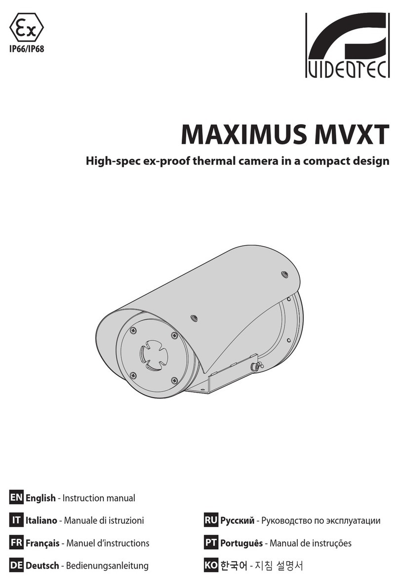
FLIR PatrolIR PTZ User manual

PatrolIR PTZ Pan and Tilt Operator’s Manual
PatrolIR PTZ
Document # 427-0001-00-11
Version 110, June 2008
Operator’s Manual
Pan and Tilt

© FLIR Systems, Inc., 2008. All rights reserved worldwide. No parts of
this manual, in whole or in part, may be copied, photocopied, translated,
or transmitted to any electronic medium or machine readable form without
the prior written permission of FLIR Systems, Inc.
Names and marks appearing on the products herein are either registered
trademarks or trademarks of FLIR Systems, Inc. and/or its subsidiaries. All
other trademarks, trade names, or company names referenced herein are
used for identification only and are the property of their respective owners.
This product is protected by patents, design patents, patents pending, or
design patents pending.
FLIR Systems, Inc.
70 Castilian Drive
Goleta, CA 93117
Phone: +1.888.747.FLIR
(+1.888.747.3547)
www.flir.com


427-0001-00-11, version 110 06/08 v
Table of Contents
1 Warnings and Cautions
2 Introduction
3 Getting Started
3.1 Parts List ................................................................................5
3.2 Operational Overview ...............................................................6
3.3 Installation .............................................................................7
3.3.1 Camera Mounting ...........................................................7
3.3.2 Fuse and Joystick Control Unit Mounting ........................10
3.4 Using your PatrolIR PTZ .........................................................14
3.4.1 Joystick Control Unit (JCU) ............................................14
4 Caring for your PatrolIR PTZ
4.1 Troubleshooting .....................................................................17
4.2 Replacing the fuses ...............................................................18
4.2.1 Cleaning ...................................................................... 19
5 Optional Accessories
5.1 Optional Extension Cables ......................................................21
6 Technical Data
6.1 Performance Specifications ....................................................23
7 Mounting Templates
7.1 Camera Mounting Template. ...................................................25
7.2 Joystick Control Unit Mounting Template. ................................27
8 Infrared Technology
8.1 History of Infrared .................................................................29
8.2 How do Infrared Cameras Work? ..............................................34
PatrolIR PTZ Pan and Tilt Operator’s Manual

vi 06/08 427-0001-00-11, version 110

427-0001-00-11, version 110 06/08 1
1
1 Warnings and Cautions
This guide uses the term Caution to indicate a potentially hazardous
situation, which, if not avoided, may result in injury, damage to the vehicle
or PatrolIR PTZ, or other property damage.
Warnings and Cautions:
Do not operate any function that takes your attention away from
safely driving your vehicle.
Any function that requires your prolonged attention should only be
performed after coming to a complete stop. Always stop the vehicle in a
safe location before performing these functions. Failure to do so may
result in an accident.
Consult your local and state driving regulations prior to
installation.
In many states using active monitors in view of the driver is prohibited.
Consult your local and state driving regulations for laws and guidelines.
User assumes all risks and indemnifies the manufacturer from any
liability.
Minimize display viewing while driving.
Viewing the display may distract the driver from looking ahead and may
result in an accident. The PatrolIR PTZ thermal imaging system should not
be used as a substitution for head lamps or head lamp assisted human
vision during vehicle operation.
Use this product for mobile 12VDC applications.
Use for other applications may result in excess heat, fire, and equipment
malfunction.
When installing the PatrolIR PTZ, do not block the vehicle’s vents
or radiator panels.
Doing so may result in heat buildup, equipment breakage, and/or fire.
Caution! Failure to follow the caution may result in damage to the
equipment or injury.

1 – Warnings and Cautions
206/08 427-0001-00-11, version 110
Caution! The PatrolIR PTZ thermal imaging system is not intended to be
used as the primary navigation system. The PatrolIR PTZ should not to
be used as a substitution for head lamps or head lamp assisted human
vision during vehicle operation. It should be used only as an aid to
cautious night-time driving.
Note: All thermal imaging systems are subject to export control.
Please contact FLIR for export compliance information concerning
your application or geographic area.

427-0001-00-11, version 110 06/08 3
2
2 Introduction
Congratulations!
The FLIR PatrolIR PTZ is a state-of-the-art thermal imaging system that
will provide you with excellent night visibility and situational awareness,
without any form of natural or artificial illumination.
The PatrolIR PTZ system is designed for simple, intuitive operation. The
basic system includes a camera assembly and a joystick control panel.
The PatrolIR PTZ uses standard 12 VDC battery power and the images
from the 320 x 240 pixel detector are compatible with virtually any
existing display and recorder that accepts composite video.
The PatrolIR PTZ is available with NTSC output, the same format used on
common television and VCR video input in the Americas and some Asian
countries. It is also available with PAL output, the same format used on
common televisions and VCR video input in Europe.
The PatrolIR PTZ features a wide field of view and is capable of providing
an image even in absolute darkness.

2 – Introduction
406/08 427-0001-00-11, version 110
The upper image represents what the human eye sees looking at a
camouflaged subject in shady brush. The lower image is an infrared
thermal picture taken at the same moment as the visible image above.
Figure 2-1: PatrolIR PTZ Makes the Difference

427-0001-00-11, version 110 06/08 5
3
3 Getting Started
3.1 Parts List
The PatrolIR PTZ camera and its accessories are delivered in a box which
contains the items below.
Description FLIR PN
PatrolIR PTZ camera
with attached 18’ cable and
wired Joystick Control Unit
with fuse holder/cigarette
lighter plug and BNC video
connector.
white color, NTSC 427-0019-01-00
white color, PAL 427-0019-02-00
Two sets of mounting hardware with whelan bracket for the camera, one
set of mounting hardware for the Joystick Control Unit, 5-amp fuses, 10
cable clips and a BNC to RCA adapter
PatrolIR PTZ Pan and Tilt Operator’s Manual 427-0001-00-11

3 – Getting Started
606/08 427-0001-00-11, version 110
3.2 Operational Overview
The PatrolIR PTZ is easy to install and operate. The system operates on 12
volts DC and there are no camera adjustments. The thermal imaging
camera inside the PatrolIR PTZ is completely sealed and extremely
rugged. The camera has been qualified for operation in all types of weather
conditions over the specified operating temperature range and includes an
automatic window heater that will prevent icing under most conditions.
Figure 3-1: Pan and Tilt PatrolIR PTZ
Monitor
(not supplied)
BNC connector
BNC to RCA adapter
(supplied)
Joystick Control Unit
Ground wire
Monitor cable
(not supplied)
12 VDC
5A Fuse
Return
PatrolIR Camera
5.5 m (18 ft) cables
Ground wire

427-0001-00-11, version 110 06/08 7
3
3 – Getting Started
3.3 Installation
It is strongly recommended that you DO NOT separate the Camera from its
base during installation.
3.3.1 Camera Mounting
Caution! The PatrolIR PTZ should be installed by a trained professional.
Incorrect installation could void your warranty.
Caution! The PatrolIR PTZ is intended to be mounted above the
mounting plane. Any other type of installation is not appropriate.
Note: An optional mounting bracket is available for the PatrolIR PTZ
that allows the unit to be mounted behind the Whelen LFL Liberty
series light bar. The front of the bracket mounts to the underside of
the lightbar and the rear is supported by adjustable, padded standoffs.
Figure 3-2: Navigator Pan and Tilt
Primary Viewing Direction
Cable
(9.50 inches)
(7.33 inches)
seal
187 mm
242 mm

3 – Getting Started
806/08 427-0001-00-11, version 110
Mount the camera with the front of the base towards the primary viewing
direction. The camera will rotate (pan) approximately 180°in either
direction from the primary viewing direction.
In order to secure the
mounting screws, manually
tilt the camera to its highest
position and rotate the body
until the access hole in the
front of the camera body is
lined up with the mounting
screw. Figure 3-3 shows a
screwdriver through the
access hole. By rotating the
camera, each of the four
mounting screws can be
tightened.
Your PatrolIR PTZ can be
installed with machine
screws, washers, lock
washers, and hex nuts as described below.
Step 1 Drill the screw mounting holes per the installation template
provided in paragraph 7.1 “Camera Mounting Template.” on page
25. A sketch is shown below in Figure 3-4.
Step 2 Check that all the screw holes line up and the front of the camera
base is towards the primary viewing direction. (The cables exit the
rear of the camera base.)
Step 3 Check the gasket under the base for integrity and using a 3mm
Allen wrench, securely fasten the camera in place with four M5
socket-head machine screws, flat washers, lock washers, and hex
nuts provided. See Figure 3-5
Step 4 Securely attach the ground wire to the vehicle ground plane.
Step 5 Route the control/power cable to the Joystick Control Unit and the
video cable to the monitor. See Figure 3-1 for a schematic
representation of the cabling connections.
Figure 3-3: Accessing the mounting screws

427-0001-00-11, version 110 06/08 9
3
3 – Getting Started
Primary Viewing Direction
5.1mm (0.20”) for machine screw
(2.47”)
This drawing is not to scale
Figure 3-4: Base Mounting Template for the Camera
1/4” x 20 mounting hole
clocking-pin hole
62.7mm
(2.47”)
62.7mm
socket head
Figure 3-5: Securing the Camera
machine screws
gasket
four places
flat washer (4)
lock washer (4)
hex nut (4)
mounting
surface

3 – Getting Started
10 06/08 427-0001-00-11, version 110
3.3.2 Fuse and Joystick Control Unit Mounting
After routing the camera cables to the desired location for the display and
the Joystick Control Unit, verify that the cables will reach before cutting
and drilling any mounting holes.
Step 1 Drill holes for the six studs and cut an access hole for mounting
the Joystick Control Unit per the installation template provided in
paragraph 7.2 “Joystick Control Unit Mounting Template.” on
page 27. A sketch is shown below in Figure 3-6.
In order to install the camera power and communication, you must
separate the keypad/joystick assembly from the back enclosure of the JCU.
Step 2 Remove the four nuts, washers, and lock washers as shown in
Figure 3-7.
Step 3 Separate the keypad/joystick assembly from the back enclosure
and slide the power and communication cable through the cable
seal (Figure 3-7).
Step 4 Connect the camera power and communication cable leads to the
Joystick Control Unit terminal block as shown in Figure 3-8, there
are six color coded wires from the two cables entering the JCU.
Refer to Table 3-1 for wiring terminations. The terminal numbers
are silk-screened onto the printed wiring board.
Caution! Changing the wiring configuration of the PatrolIR PTZ or
attempting to utilize controllers or wiring harnesses other than those
supplied by FLIR may cause permanent damage to the unit and may void
the warranty.
Caution! Do not connect the camera to anything other than 12 VDC
power. Operating the camera outside of the specified input voltage
range or the specified operating temperature range can cause
permanent damage.

427-0001-00-11, version 110 06/08 11
3
3 – Getting Started
Figure 3-6: Joystick Control Unit mounting template
This drawing is not to scale
Top of JCU
DRILL 6.4mm (0.25”) for
(5.50”) (5.20”)
(2.375”)
threaded stud six places
CUT for JCU
(1.35”)
(1.25”)
60.325mm
31.75mm
132mm
34.3mm
139.7mm
(1.25”)
31.75mm
Figure 3-7: JCU Disassembly
mounting
studs (2)
nuts and washers (4 each)
terminal block

3 – Getting Started
12 06/08 427-0001-00-11, version 110
Step 5 Re-attach the keypad/joystick assembly to the back enclosure. The
cables will easily slide through the cable seal. Secure using the
four nuts, washers, and lock washers as shown in Figure 3-7.
Step 6 Check the gasket under the Joystick Control Unit for integrity and
securely fasten the switch in place with the two M4 flat washers,
lock washers, and hex nuts provided.
Step 7 Securely attach the ground wire to the vehicle ground plane.
Table 3-1: JCU Terminal block connections
Signal name and source Wire color
Terminal
block
location
+12VDC IN—from main electrical power cable Red #1
12VDC RETURN—from main electrical power cable Black #2
+12VDC OUT—to camera control/power cable Red #3
12VDC OUT RETURN—to camera control/power cable Black #4
-RS422 OUT—to camera control/power cable Green #5
+RS422 OUT—to camera control/power cable White #6
Figure 3-8: Control and power connections to JCU terminal block
Red lead from
camera harness
Green lead from
camera harness
Red fused lead
to main electrical
+12V power
Black lead from
camera harness
Black lead to main
White lead from
camera harness
electrical return
Ground lug

427-0001-00-11, version 110 06/08 13
3
3 – Getting Started
Step 8 Connect the 12 VDC power and return wires from your fuse panel
to the JCU wiring harness. Wire must be 16 gage.
Note: Depending on your JCU mounting location you may want to
connect the ground wire and power cables either before or after
installing the JCU.

3 – Getting Started
14 06/08 427-0001-00-11, version 110
3.4 Using your PatrolIR PTZ
The PatrolIR PTZ is easy to use, but you should take a moment to carefully
read this section so you fully understand how to use the controls and what
you are seeing on your display. While the imagery you will see on the
monitor may look like black and white daylight video, it isn’t! A few tips on
how to interpret some of the imagery will help you to make the most of
your system.
3.4.1 Joystick Control Unit (JCU)
Your new PatrolIR PTZ camera system is controlled with the touch pad and
the joystick shown at the right.
On/Off—enables the camera video and the JCU
camera controls. This On/Off switch does not affect
power to the camera; it only affects the video signal
and pan/tilt control. The camera power must be
controlled with a customer-provided switch or circuit
breaker.
DIM—controls the brightness of the JCU panel;
enabled anytime power is on.
HOME—moves the camera to the last home position
setting. Or, when held down for at least four seconds,
sets the current position as the home position.
ZOOM—selects either 1x or 2x as the zoom setting.
SCENE—cycles through gain settings to change the brightness and contrast
of the image. Varying environmental conditions may make one setting
more appropriate than another for any operation.
B/W—selects black hot, white hot, or red hot video image mode. Hot object
appear black, white, or red respectively depending on the selected mode.
Caution! The PatrolIR PTZ imaging system is not intended to be used as
the primary navigation system. It should be used in conjunction with
other navigation aids and a primary manual navigation system.
Table of contents
Other FLIR Thermal Camera manuals

FLIR
FLIR GF309 User manual

FLIR
FLIR M-Series User manual

FLIR
FLIR T4xx series User manual

FLIR
FLIR FLIR H Series User manual

FLIR
FLIR FLIR H Series User manual

FLIR
FLIR M300 Series User manual

FLIR
FLIR Voyager II User manual

FLIR
FLIR EVS3 Manual

FLIR
FLIR SR-100 User manual

FLIR
FLIR Voyager II Installation and operating instructions