MNTZ36PP Parapet Mount Bracket User’s Manual
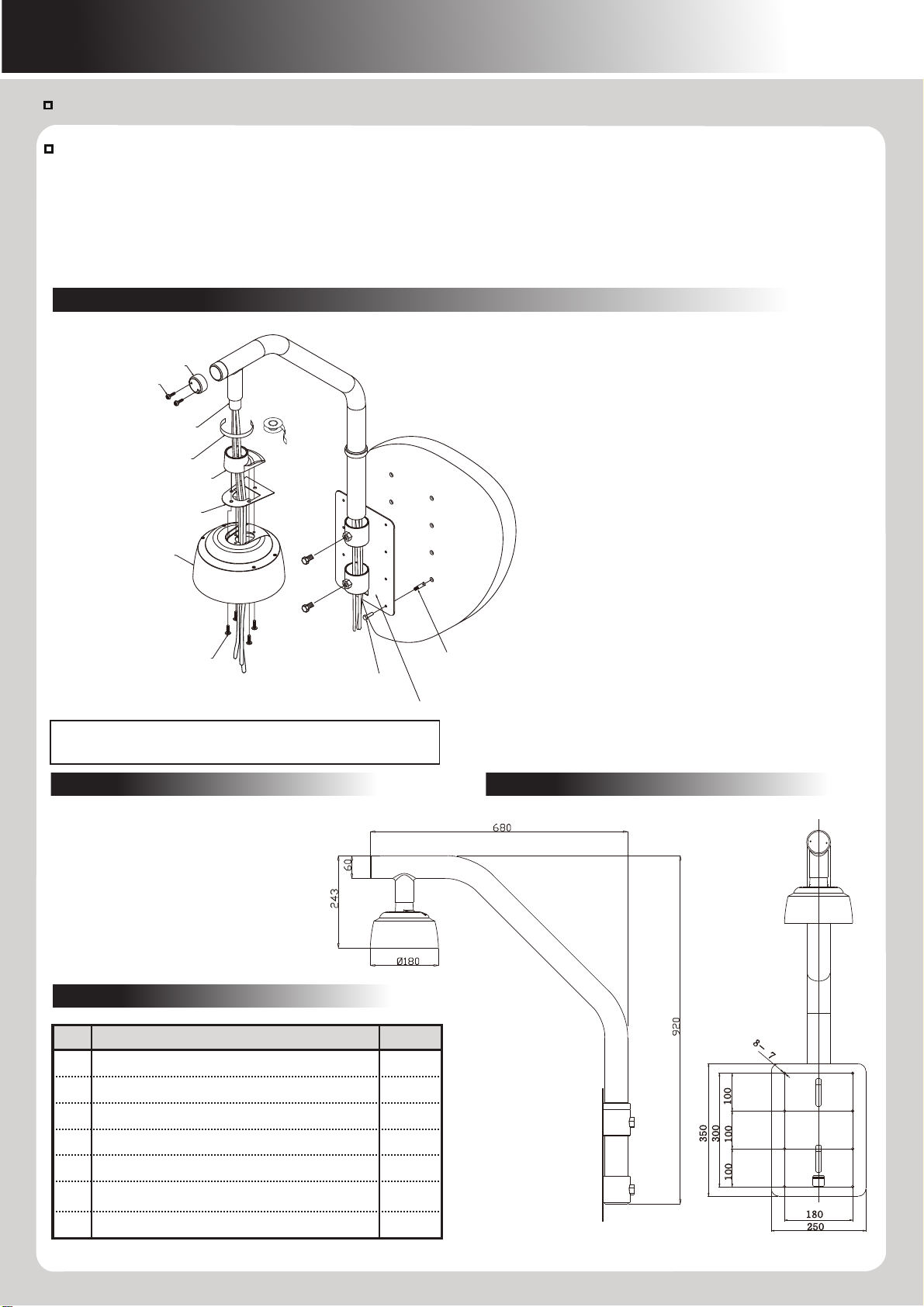
Dimensions
Installation
Description
Accessories
- Aluminum & Steel body
- Unit : 5.8Kg
- Maximum load : 20Kg
Part Name
HEX BOLT 1/4" (PARAPET)
HEX BOLT 16x20 (SUS)
ANCHOR 1/4" (SUS)
SCREW PH M4x8 (SUS)
RUBBER GASKET (SILICON)
SEAL TAPE (12mm)
PH MS M3x10(SUS)
Q'ty
8
2
8
4
1
1
2
No
1
2
3
4
5
6
7
① Drill a hole in the surface for the cables and run the
cables through the cable hole.
② Drill 8 anchor holes in the surface according to the hole
pattern in the parapet plate.
③ Insert the anchors (8ea). Run the cable through the
parapet plate and use the ¼” hex bolts (8ea) to fasten
the parapet plate to the surface.
④ Feed the cable through the pipe and set the pipe on the
parapet plate using the 16x20 hex bolts (2ea).
⑤ Feed the cable down through the pipe socket. Wrap seal
tape around the pipe socket.
⑥ Attach the pipe cover to the pipe using the PH M3x10
screws (2ea).
⑦ Insert the rubber gasket between the camera adapter
and the adapter flange and connect the adapter flange to
the camera adapter using the PH M4x8 screws (4ea). Run
the cables through the camera adapter assembly, and
screw the camera adapter assembly onto the pipe
socket.
⑧ Install the camera into the camera adapter
(see instructions on back of sheet).
MS PH M4x8
SUS 4EA
RUBBER GASKET
PIPE COVER
PH MS M3 x 10 (SUS) : 2 EA
ADAPTER FLANGE
CAMERA ADAPTER
ANCHOR 1/4” 8EA
PARAPET PLATE
HEX BOLT 1/4”
PIPE SOCKET
SEAL TAPE
HEX BOLT
16x20
NOTE: Camera installation requires the M4x12 mounting screws supplied with the
camera. Make sure the o-rings are attached to the mounting screws and dome cover
torx screws to prevent water ingress.
Compatible with Digimerge Camera Models: DPZ36WO23 / DPZ36WO30
Usage Cautions and Warnings
Please read through the User Manual and all safety instructions prior to use.
•All the safety and operating instructions should be read before installing. Follow
all operating instructions.
•Installation must be performed by a trained professional.
•Do not use the product with cameras other than the recommended models.
•The mounting has to be installed onto a firm and stable location that can
support the weight of the camera and mount. Ensure all parts are completely secured.
•Do not use the product for other purposes.
Product Characteristics
This product has been designed to be used in the installation of speed dome cameras. This product has been
fabricated using strong, corrosion-free aluminum alloy material.
Prior To Installation
Avoid installing the mounting onto an unstable structure such as a gypsum wall panel. Install the mounting onto a strong structure
such as a concrete wall, steel beam, etc. Use concrete screws with plugs or other installation tools when installing the mount onto
a concrete structure. Make sure that all the screw parts are metallic.
Avoid screwing too close to the edge of a piece of wood when screwing into a wooden structure.
□
CABLE


