Flo CoRe+ User manual

TM
TM
Installation Guide
Table of Contents
1.1.
1.2.
1.3.
3.1.
3.2.
3.3.
3.4.
3.5.

1. About CoRe+ MAX
The CoRe+ MAXTM is part of a family of Level 2 charging stations that are suitable for a wide
range of parking layouts, including workplaces, condos, apartments, fleets, and commercial
properties. They are ideal for sites where several high-capacity electric vehicles such as
commercial service trucks and school buses need to charge simultaneously because the
chargers can be cascaded to minimize installation costs for the entire site.
1.1. Canada and USA Electromagnetic Interference
Regulatory Statement
This equipment has been tested and found to comply with the limits for a Class A digital
device, pursuant to part 15 of the FCC Rules. These limits are designed to provide
reasonable protection against harmful interference when the equipment is operated in a
commercial environment. This equipment generates, uses, and can radiate radio frequency
energy, and if it is not installed and used in accordance with the instruction manual, it may
cause harmful interference to radio communications. Operating this equipment in a
residential area is likely to cause harmful interference, in which case the user will be
required to correct the interference at their own expense.
This device contains license-exempt transmitters and receivers that comply with
Innovation, Science and Economic Development Canada’s license-exempt Radio Standards
Specifications (RSSs). Operation is subject to the following two conditions:
1. This device may not cause interference.
2. This device must accept any interference, including interference that may cause
unwanted operation of the device.
Changes or modifications to this equipment that have not been expressly approved by
FLO may void the user’s authority to operate this equipment.
Exposure to radio frequency energy: The radiated power output of the communication
modules included in this device is below the limits recommended for the general
population for uncontrolled exposure as defined in the FCC standards. This device
should be operated with a minimum distance of at least 20 cm (7.87’’) between itself and
a person’s body, and it must not be co-located or operated with any other antenna in
order to comply with the conditions of the FCC grants.
1.2. Important Safety Instructions
Read all the instructions before using this product.
PLEASE SAVE ALL THE INSTRUCTIONS OF THIS MANUAL.
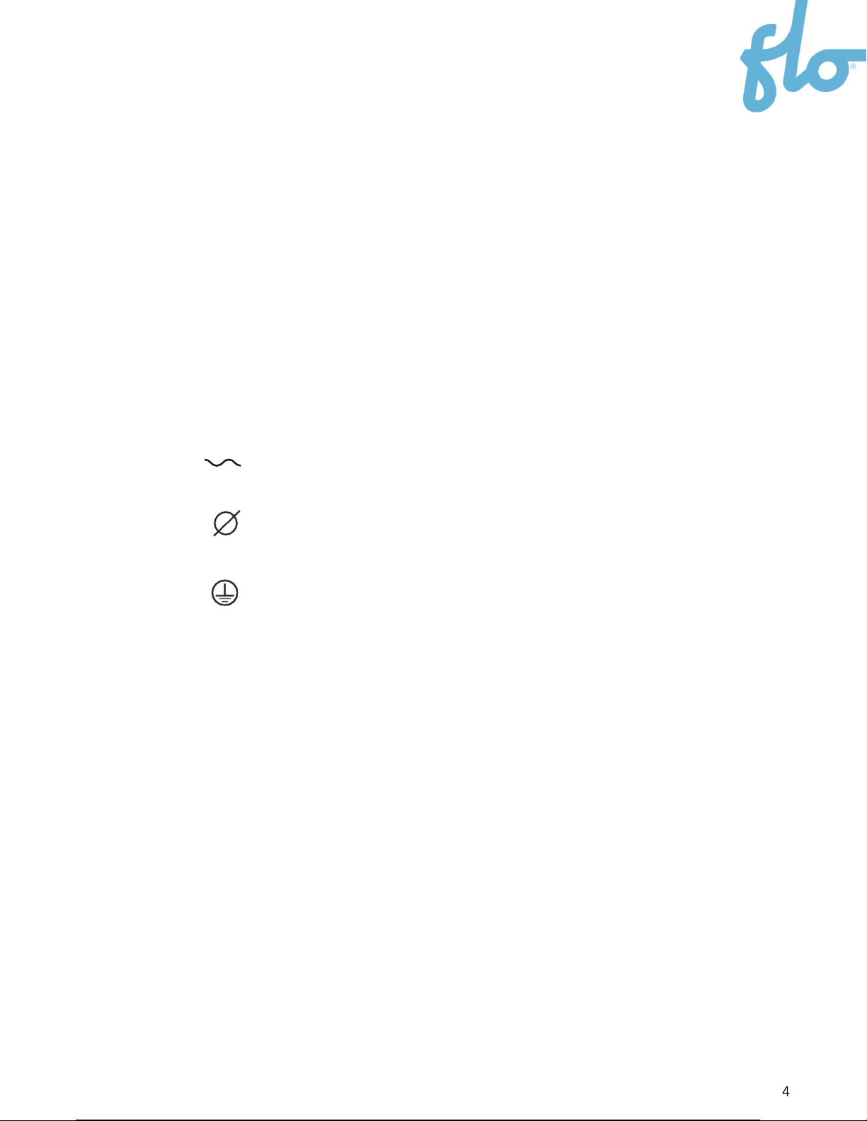
1.2.1. Safety Symbols on your Unit
Alternating current
Phase
This unit is equipped with a protective conductor
terminal
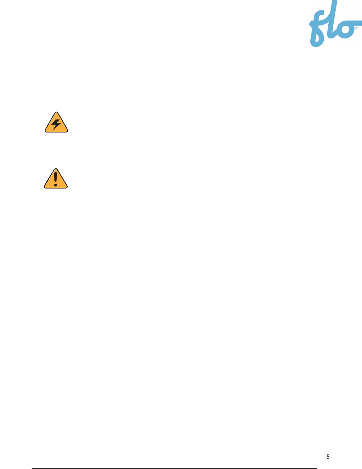
1.2.2. Instructions Pertaining to the Risk of Fire or Electric
Shock
This symbol is used to warn you about hazardous voltage and the possibility of
electric shock.
When using electrical products, basic precautions should always be followed,
including the following. This manual contains important instructions for the
CoRe+ MAX model that must be followed during the installation, operation, and
maintenance of the unit.
This symbol is used to make you aware of important safety information in
these instructions.
1.2.3. Important General Safety Instructions
Always follow the safety instructions below when installing or using the electric vehicle
chargers:
Children should be supervised around the device while it is in use.
Never insert your finger into the electric vehicle connection.
Never use the Electric Vehicle Supply Equipment (EVSE) if the flexible power cord or
Electric Vehicle (EV) cable is frayed, has broken insulation, or shows any other signs
of damage.
Never use the EVSE if the EV connector enclosure is broken, cracked, open, or shows
any other signs of damage.
This EVSE was designed to be used with electric vehicles equipped with an SAE-
J1772 connector.
This EVSE must only be used to charge vehicles that do not require a ventilated
environment during charging.
Make sure to always disconnect the power supply of the EVSE before servicing it.
Avoid installing the EVSE in bad weather conditions.

CAUTION
Always use a manual screwdriver. DO NOT use an impact driver for the
screws at any time. This will void the warranty.
CAUTION
To reduce the risk of fire, only connect to a circuit equipped with
appropriate branch circuit overcurrent protection (see the
Rotary
Position Table
in
section 1.3.1.
) in accordance with the
Canadian
Electrical Code (CSA C22.1-12)
and the
National Electrical Code
(ANSI/NFPA 70).
1. Handle packaging with care. Always use safety glasses and gloves when unpacking
and installing the device.
2. Contact a certified contractor, a certified electrician, or a trained installer to ensure
compliance with local building codes, regulations, security standards, and weather
conditions.
3. Verify with local authorities that the location where the EVSE is to be installed is free
from underground pipelines or electrical equipment; otherwise, you might inflict
serious injuries on yourself and others.
4. This EVSE is designed to be wall-mounted or pedestal-mounted.
5. If installed on a wall mount configuration, do not install on or over a combustible
surface.
6. Ensure that the types of mounting surfaces of the wall and the posts are strong
enough to support more than 56.7 kg (125 lbs.) per anchoring point in the vertical and
horizontal direction.
7. Make sure that the anchors are compatible with the type of mounting surface.
8. This product must be connected to a grounded, metal, permanent wiring system.
When this is not possible, an equipment grounding conductor must be run with the
circuit conductors and connected to the equipment grounding terminal and installed
by a certified electrician.
9. Altering any part of the EVSE will automatically void the warranty.
1.3. Site Preparation Considerations Prior to
Installation
Avoid installing the Electric Vehicle Supply Equipment (EVSE) in bad
weather conditions.
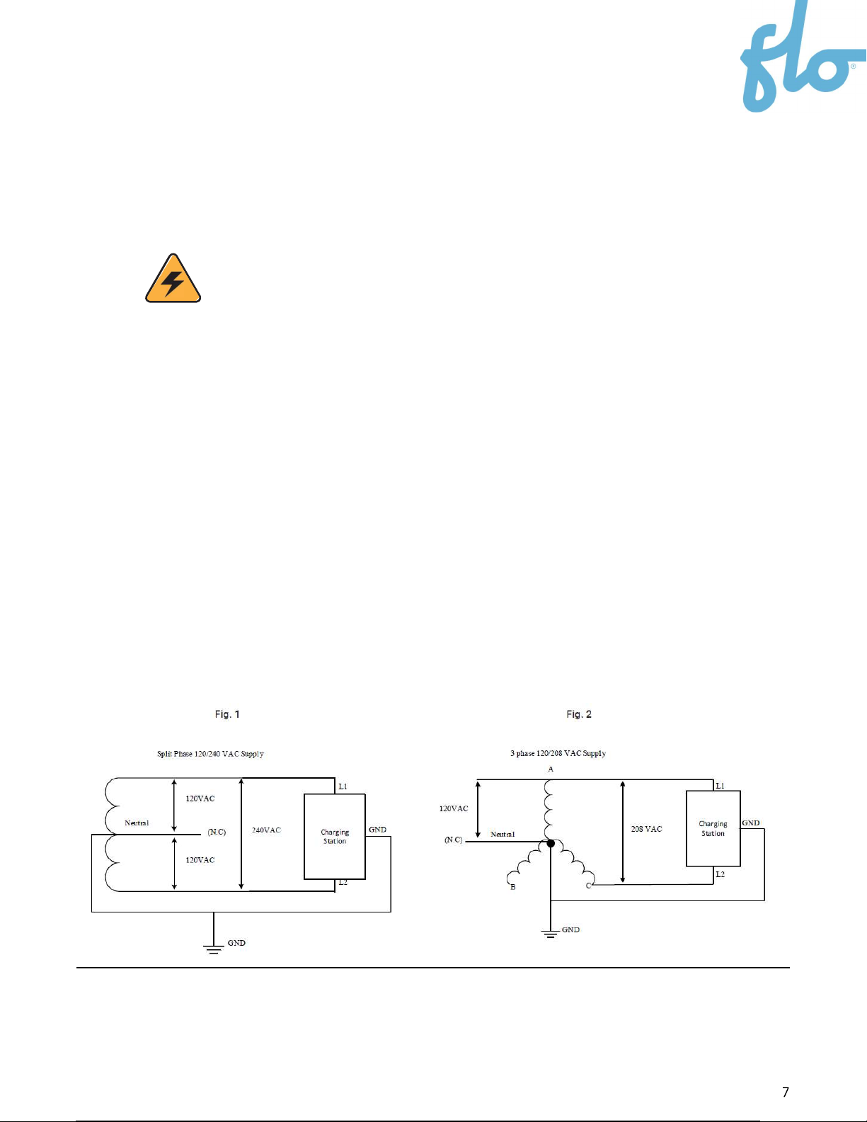
Split Phase 120/240 VAC supply or single phase 120/208 VAC. Refer to
Figure 1
and
Figure 2
in the image below.
Both lines must have 120 V between ground.
The voltage supply must be grounded.
The electrical wiring requires 2 lines and 1 ground connection. Neutral is not used.
Refer to Figure 1 and Figure 2.
Maximum output power: 19.2 kW @ 240 VAC or 16.6 kW @ 208 VAC.
Built-in protection against overvoltage conditions and leakage current to ground.
Use 90 °C (194 °F) copper wire conductors only.
Field terminals accept wires between 3 AWG and 14 AWG.

1.3.1. Rotary Position Table
Rotary
Position
Charging
Station
Current (A)
Recommended
Circuit
Protection (A)
Recommended
Wire Gauge
(AWG)
0 80 100
3
1
72
90
3
2
64
80
4
3 59 80
4
4 56 70
4
5
48
60
6
6
40
50
6
7 32 40
8
8 24 30 10
9
16
20
14
2. Communication Gateway
Install the Communication Gateway prior to the commissioning of the station. The
communication gateway is the property of FLO. Fees will be charged if the gateway is
damaged, lost, or not installed according to the installation guide.
Outdoor installation is recommended. The Customer must provide a waterproof PVC box
and install it less than 48.7 m (160’) from the stations.
Refer to the
Communication Gateway Installation Guide
for more information. Contact us
once the communication gateway has been installed to validate the signal levels and
activate commissioning or for any other questions: 1 855 543 8356.

3. Installation Instructions
The CoRe+ MAX can be mounted on a wall or pedestal. Depending on the installation, the
power cables can be connected in three different ways (see
sections 3.2 to 3.4).
If
mounted on a CoRe+ MAX pedestal, please refer to the
CoRe+ MAX Pedestal Installation
Guide
for the pedestal installation procedure prior to the CoRe+ MAX installation.
3.1. Dimensions and Nominal Installation Location
FLOOR
190.5 mm
[7.5"]
476.2 mm
[18.75"]
1333.5 mm
[52.5"]
1219.2 mm
[48"]
292.1 mm
[11.5
139.7 mm
[5.5"]
95.2 mm
[3.75"]
48.3 mm
[1.9"] 330.2 mm
[13"]
1308.1 mm
[51.5"]
1106 mm
[43.5"]
977.9 mm
[38.5"]
Back side: 2 matching holes and a
rectangular cable opening when
pedestal is mounted

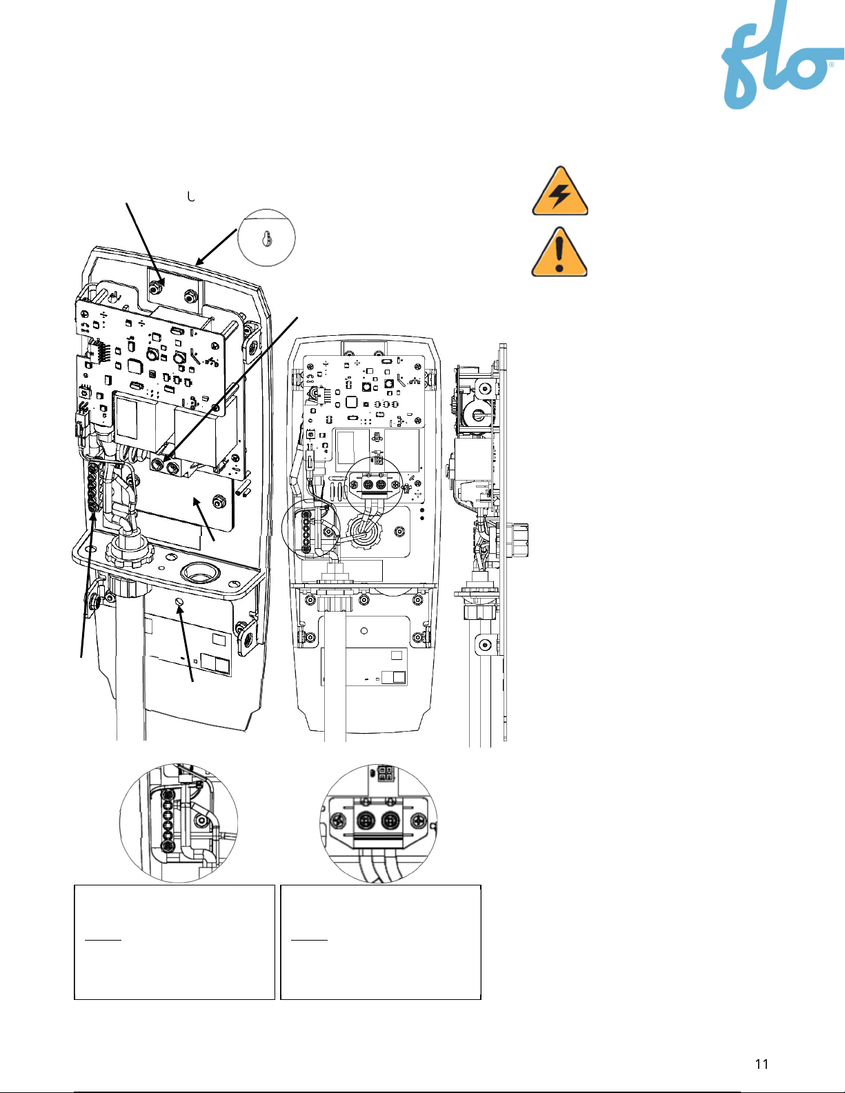
3.2. Power Cable Installation Under the Station
Follow the steps below to install the power cable
under the station:
1. Attach the head base to the wall or post with
an anchoring apparatus that can support at
least 56.7 kg (125 lbs.) per anchor point (2) in the
vertical and horizontal direction.
2. Hang the head base on the upper anchor
(previously attached to the wall or post) via the
upper anchor keyhole. While doing so, ensure
that there is a tight fit and that there is no gap
between the gasket and the mounting wall.
3. Complete the mounting of the head base by
screwing a mounting bolt through the bottom
anchor hole.
4. Remove the hole cover and attach the cable
connector to the hole from the bottom, then
insert the power cable. Ensure that the
conductors are long enough to reach the
terminal block. Make sure to seal the cable hole
correctly. Ensure that the cable is attached
properly by tightening the cable connector (not
included).
Note that the hole is 3.5 cm (1.375”).
5. Connect the two power conductors (L1 and
L2) and the ground conductor (GND) as
indicated with the appropriate torque.
6. The ground conductor must be connected to
the terminal ground.
Avoid installing the EVSE in bad
weather conditions.
IMPORTANT
The protection plate should always
remain over the keyhole.
Ground conductor connection
- GND
Torque
6 AWG 4 N-m [35 lb-in]
8 AWG 2.8 N-m [25 lb-in]
10 AWG 2.3 N-m [20 lb-in]
A B
Power conductor connection –
L1L2
Torque
3 AWG 3 N-m [27 lb-in]
4 to 14 AWG 2.5 N-m [22 lb-in]
Protection plate Upper anchor keyhole
Ground
terminal
Bottom
anchor hole
Hole cover
Power terminal
A
B
3.3. Power Cable Installation from the Back
Upper anchor keyhole
A
B
Backplate
Protection
plate
Power terminal
Ground
terminal Bottom anchor
hole
1. Attach the head base to the wall or post with
an anchoring apparatus that can support at
least 56.7 kg (125 lbs.) per anchor point (2) in
the vertical and horizontal direction.
2. Hang the head base on the upper anchor
(previously attached to the wall or post) via
the keyhole at the top. While doing so, ensure
that there is a tight fit and that there is no gap
between the gasket and the mounting wall.
3. Complete the mounting of the head base by
screwing a mounting bolt through the bottom
anchor hole.
4. Remove the back plate to prevent particle
splatter on the equipment.
5. Punch a hole of the appropriate diameter in
the back plate to install the cable connector.
Note that the pre-punched hole diameter on
the back plate is 34.5 mm (1.36’’).
6. Put the back plate back in its place.
7. Install the cable connector in the hole
punched into the back plate, then install the
cable. Ensure that the conductors are long
enough to reach the terminal block. Make sure
that the hole is sealed properly.
8. Connect the two power conductors (L1 and
L2) and the ground conductor (GND) as
indicated with the appropriate torque.
9. The ground conductor must be connected
to the terminal ground.
Avoid installing the EVSE in bad
weather conditions.
IMPORTANT:
The protection plate should
always remain over the keyhole.
Ground conductor connection
- GND
Torque
6 AWG 4 N-m [35 lb-in]
8 AWG 2.8 N-m [25 lb-in]
10 AWG 2.3 N-m [20 lb-in]
A B
Power conductor connection –
L1L2
Torque
3 AWG 3 N-m [27 lb-in]
4 to 14 AWG 2.5 N-m [22 lb-in]

3.3.1. Power Cable Entry on a Station with an Electrical Box
or CoRe+ MAX Pedestal
Avoid installing the EVSE in bad
weather conditions.
IMPORTANT:
The protection plate should
always remain over the keyhole.
1. Remove the back plate.
2. Install the head base to align the rectangular
opening with the box opening in the wall or post.
3. Attach the head base to the wall or post with
an anchoring apparatus that can support at
least 56.7 kg (125 lbs.) per anchor point (2) in
the vertical and horizontal directions.
4. Hang the head base on the upper anchor
(previously attached to the wall or post) via the
keyhole at the top. While doing so, ensure that
there is a tight fit and that there is no gap
between the gasket and the mounting wall.
5. Complete the mounting of the head base by
screwing a mounting bolt through the bottom
anchor hole.
6. Make sure that the opening between the
charging station and the electrical box or
pedestal is properly sealed.
7. Connect the two power conductors (L1 and
L2) and the ground conductor (GND) as
indicated with the appropriate torque.
8. The ground conductor must be connected to
the terminal ground.
Protection plate Upper anchor keyhole
Power terminal
Back plate
Ground
terminal Bottom anchor
hole
A
B
Ground conductor connection
- GND
Torque
6 AWG 4 N-m [35 lb-in]
8 AWG 2.8 N-m [25 lb-in]
10 AWG 2.3 N-m [20 lb-in]
A B
Power conductor connection –
L1L2
Torque
3 AWG 3 N-m [27 lb-in]
4 to 14 AWG 2.5 N-m [22 lb-in]
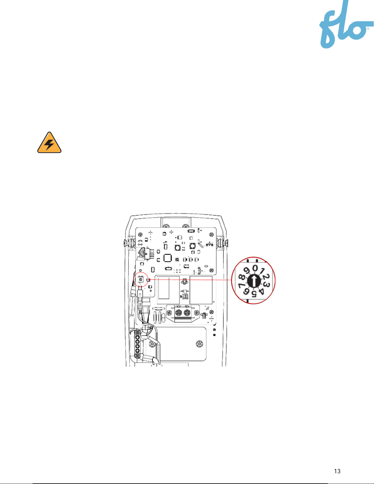
3.3.2. Setting the Current Limit
By default, the CoRe+ MAX is set to maximum power in the factory. If your electrical
infrastructure does not allow the charging station to operate at maximum power, it can be
reduced using the Current Limiter Switch.
WARNING
Make sure that the power is off.
Follow the steps below to set the current on the charging station:
1. Locate the Current Limiter Switch on the main Printed Circuit(PC) board.
2. Using a flat-head screwdriver, gently rotate the switch to the desired position. Refer
to the following table to determine the rotary position:
Rotary Position Charging Station Current (A)
0
80
1
72
2 64
3 59
4 56
5
48
6 40
7 32
8 24
9
16
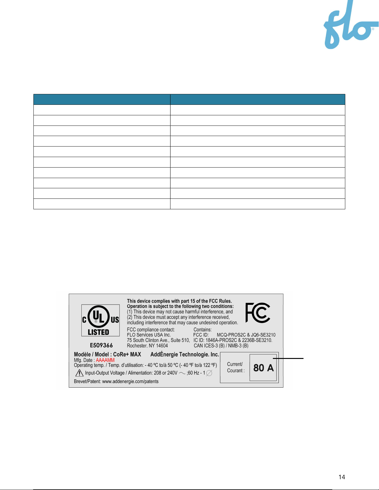
3. Detach the corresponding maximum current setting label sticker from the label set
kit that comes with the unit. Stick it over the existing label on the charging station
enclosure to inform the maintenance personnel of the maximum current setting.
Proof of installation will be required to complete the commissioning to ensure that
the label corresponds to the installation. This is important for safety and warranty
validity considerations.
Current
sticker

3.4. Closing the Station Housing
1. Ensure that the gasket on the lip shown below is properly aligned.
2. Connect the data cable to its respective connector as shown below.
WARNING: NEVER CONNECT/DISCONNECT THE DATA CABLE WHEN THE CHARGING
STATION IS ENERGIZED. THIS COULD DAMAGE THE UNIT.
Gasket
Groove

3. Align the housing groove to the charging station lip and push the housing toward the
charging station, ensuring that the gasket stays in place.
4. Apply slight pressure to the front cover, then screw on the top 2 bolts, ensuring that
the O-rings stay on the screws. Screw on the bottom 2 bolts. Tighten all screws to 30
lb-in (3.4 N-m).
WARNING: NEVER USE AN IMPACT DRIVER TO AVOID DAMAGING THE THREADS!
Lip
gasket

5. Place the charging cable on the cable holder and the charging connector in the
receptacle.

3.5. Preliminary Tests and Commissioning
Follow the steps below to complete the preliminary tests and
commissioning:
1. Turn on the power to the charging station. You should be
able to observe the following results immediately after the
power is turned on:
a. The status light is on continuously; its color is green.
b. The greeting message is displayed.
NOTE: If no message appears, ensure that the data cable is
connected by following step 2 in
section 3.4. 3.4.
while the
station is NOT energized.
2. Scan the access card provided with the charging head. You
should be able to observe the following results:
a. Once the reader detects the card, it will emit an audible
beep.
b. Immediately after the beep, the access card will be authenticated by the
charging station.
c. If the authentication of the card is successful, the automated test of the
protection circuit will be performed.
d. Once the test is successfully completed, the overhead status light will start
flashing (white).
e. If the connector is inserted into an electrical vehicle, it will begin charging. If it
does not begin charging after 1 minute, the charging station is in wait mode.
3. Once the charging station successfully passes the preliminary test, the charging
station can be used as a private charging station (using the provided access cards)
or be connected to FLO’s management system by turning on the communication
gateway provided by FLO. Call FLO Services at the number provided on the sticker in
front of the charging station to process the commissioning step. If the
commissioning is not completed, the station will be limited to 6 A when
manufactured in power sharing mode.

3.5.1. Station Status Light Indicator
Color
Meaning
Green - Solid color The charging station is ready for session
activation.
White - Blinking
Session
authenticated;
the charging station is
ready to plug into the electric vehicle (EV).
Blue - Solid color The charging station is plugged in, and energy is
being delivered.
Red
-
S
olid color
Critical fault
Off Out of service

4. Power Sharing
The CoRe+ MAX can be configured in standard or power sharing mode. With the integrated
power sharing capability of the CoRe+ MAX, a maximum of four charging stations sharing
the same 100 A circuit for a total load of 80 A can be connected in parallel to the same
branch circuit. Here are some characteristics of power sharing mode:
The charging stations connected in parallel to the same branch circuit must all be
CoRe+ MAX models (the specific model identification can be found on the unit
label).
To allow for dynamic current sharing, a site controller application must be
installed and properly configured by FLO.
Without a site controller installed or in operation, or in the event of a loss of
communication, each CoRe+ MAX limits its output to 6 A when set in power
sharing mode.
The site controller will then ensure that the maximum available current is shared
optimally among the charging stations (between 6 A and 80 A for each station)
while ensuring that the maximum circuit capacity (80 A in the case of a circuit
protected by a 100 A breaker) is never exceeded.
For safety reasons, each CoRe+ MAX charging station will immediately interrupt
an ongoing charging session when the connected EV draws more than the
specified amperage limit at any time. To resume charging, the user must restart
the usage session process from the beginning.
The site controller is provided by FLO as part of its Global Management Service
(GMS).
The communication between the site controller and the charging station is done
through a wireless meshed Zigbee network. A communication gateway must
therefore be installed. Refer to the Communication Gateway Installation Guide
provided by FLO for further details.
The maximum number of charging stations sharing the same 100 A circuit (for a total load of
80 A) is 4.
Other manuals for CoRe+
5
Table of contents
Other Flo Automobile Accessories manuals


