Flo SmartDC User manual

SmartDC
Installation guide

SmartDC
Installation Guide
2

SmartDC
Installation Guide
3
Table of contents
Safety ..............................................4
Specications .......................................5
Specications and center of gravity ....................6
Exterior view of the station............................7
Interior view of the station ............................8
Typical installation ...................................9
Site preparation.....................................10
Installing the base onto a concrete floor slab...........11
Lifting and handling of the station ....................12
Installing the station onto the base....................13
Installing the counterweight..........................14
Installing the top sign ...............................15
Electrical connections to the station ..................16
Station start-up .....................................17
Care and maintenance of the station ..................18

SmartDC
Installation Guide
4
Safety
WARNING: RISK OF ELECTRICAL SHOCK, DO NOT OPEN.
Before servicing, disconnect AC power using external contactor and unplug charging connectors from electric vehicles.
IMPORTANT SAFETY INSTRUCTIONS - PLEASE DO NOT DISCARD THESE INSTRUCTIONS
Carefully read this guide before installing the EVSE.
1. This station was designed to be ground-based and installed on a non-combustible surface.
2. Check with local authorities that the location where the EVSE is to be installed is free of underground pipelines or electrical equipment,
otherwise you could cause serious injury to yourself.
3. Connect the power station's supply with copper or aluminum conductors sized in conformity with the local code for a three-phase,
480 Y/277 V, 54 kVA (50 kW version) or 108 kVA (100 kW version) circuit, rated for usage at a maximum temperature of at least 75°C / 167°F.
4. Grounding: to ensure the safe operation of the station, it must be connected to a grounding circuit compliant with local regulations and
installed by a certied electrician.
5. Communicate with a certied contractor, certied electrician or trained installer to ensure compliance with local building code, regulation,
security standards and weather conditions.
6. Any alteration of a part of the station will automatically void the warranty.
7. Handle parts with care, since they can be sharp-edged. Always use safety glasses and gloves when unpacking and installing.
8. Some parts are heavy and could cause injury. Use proper lifting techniques and wear safety boots at all times during the installation.
9. Never insert your ngers into the electric vehicle’s connector.
10. Never use the station if the flexible power cords seem damaged, or if the insulation is damaged.
11. Never use the station if the main case is broken, cracked, open, or damaged.
12. This station was designed to be used with electric vehicles equipped with a CHAdeMO or SAE J1772 Combo port.
13. This station is to be used to charge vehicles that do not require a ventilated environment during charging.
14. Replacement of the station’s parts must be performed by qualied service personnel.
15. Do not install the station on or over combustible surfaces.
FCC NOTICE (FOR USA ONLY)
This equipment has been tested and found to comply with the limits for a Class A digital device, pursuant to Part 15 of the FCC Rules. These limits
are designed to provide reasonable protection against harmful interference when the equipment is operated in a commercial environment. This
equipment generates, uses, and can radiate radio frequency energy and, if not installed and used in accordance with the instruction manual, may
cause harmful interference to radio communications. Operation of this equipment in a residential area is likely to cause harmful interference in which
case the user will be required to correct the interference at his own expense.
The enclosed device complies with Part 15 of the FCC Rules. Operation is subject to the following two conditions: (i.) this device may not cause
harmful interference and (ii.) this device must accept any interference received, including interference that may cause undesired operation.
Exposure to Radio Frequency Energy: The radiated power output of the communication modules included in this device is below the limits
recommended for the general population for uncontrolled exposure as dened in the FCC standards. This device should be operated with a minimum
distance of at least 20 cm between itself and a person’s body and must not be colocated or operated with any other antenna in order
to comply the conditions of the FCC Grants.
Modications not expressly approved by AddÉnergie Technologies inc. could void the user’s authority to operate the equipment.

SmartDC
Installation Guide
5
Specications
50 kW 100 kW
Type of charging station Direct-current fast charging station
Output connector SAE J1772 Combo and CHAdeMO
Input connector Screw type distribution bloc, 500MCM (for the phases and neutral), 2/0 max for ground.
Nominal voltage supply Three-phase 480 Y/277 V (must be protected by a 100 A,
three-phase over-current protection device)
Three-phase 480 Y/277 V (must be protected by a 200 A,
three-phase over-current protection device)
Maximum power consumption 54 kVA 108 kVA
Maximum output power 50 kW 100 kW
Efficiency 93% or better
Power Factor 98% or better
Delivered weight 300 kg (675 lbs)
The charging station is a non linear load.
Integrated Protection:
• Against voltage surges
• Electric current leakages to ground
• Isolation failures between the DC output and ground
• Safety ground failures between the charger and the ground vehicle
Operating Temperature: -40°F to 122°F
Casing: Conforms to the NEMA Type 3R standards for exterior use
Security standards compliance:
• UL 2202 : Standard for Electric Vehicle (EV) Charging System Equipment
• UL 2131-1, UL 2131-2 : Standard for Safety for Personnel Protection Systems
for Electric Vehicle (EV) Supply Circuits
• CSA C22.2 NO. 107.1-16 : General Use Power Supplies
• CSA C22.2 NO. 281.1-12, CSA C22.2 NO. 281.2-12 : Standard for Safety for
Personnel Protection Systems for Electric Vehicle (EV) Supply Circuits
• FCC part 15 Class A
• ICES-3(A) / NMB-3(A)
Model: SmartDC
Version: V3
Company Info: AddÉnergie Technologies Inc
Document revision number: US.11.2019.v1
©2019 AddÉnergie Technologies Inc. All rights reserved. Such material is protected by copyright laws of multiple
countries, and may not be modied, reproduced, or distributed without the prior written consent of AddÉnergie
Technologies.
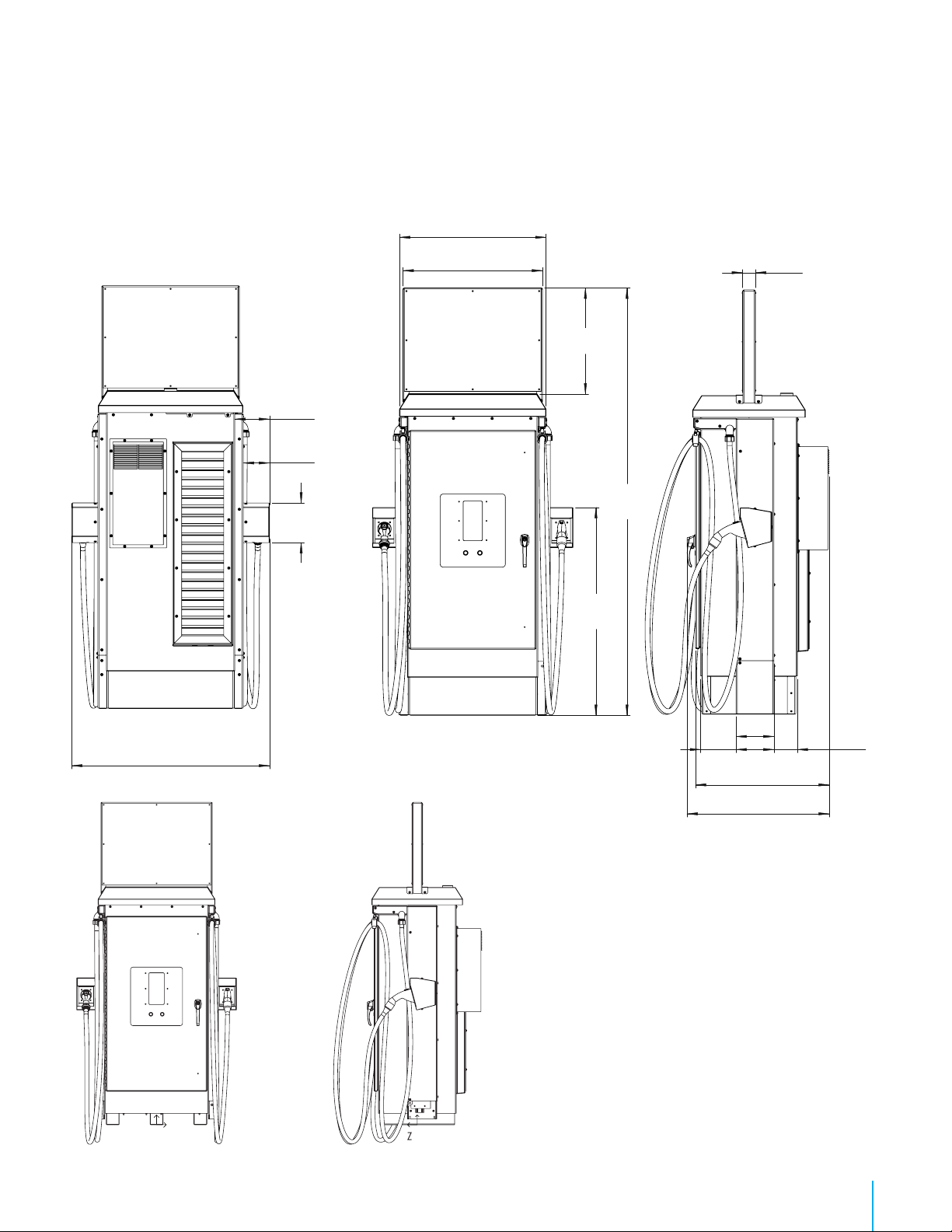
* Shown with optional cable management system installed.
SmartDC
Installation Guide
6
36.00 in
8.63 in
6.50 in
9.88 in
49.25 in
34.29 in
26.09 in
3.25 in
105.28 in
51.21 in
5.81 in8.81 in
9.38 in
33.17 in
35.27 in
* Shown with optional cable management system installed
CoG (approx)
X 25 mm (1 in)
Y 940 mm (37 in)
Z 58 mm (-2 in)
X
Y
Y
Specications and Center of Gravity

SmartDC
Installation Guide
7
Exterior preview of the station
A : Locking door handle
B : Start button
C : Stop button
D : Display
E : RFID card reader
F : SAE J1772 Combo connector
G : CHAdeMO connector
H : Base
I : Air intake
J : Cable management system
K : Heat exchange unit
A
B
D
E
F
C
G
K
I
H
J
SmartDC
Installation Guide
8
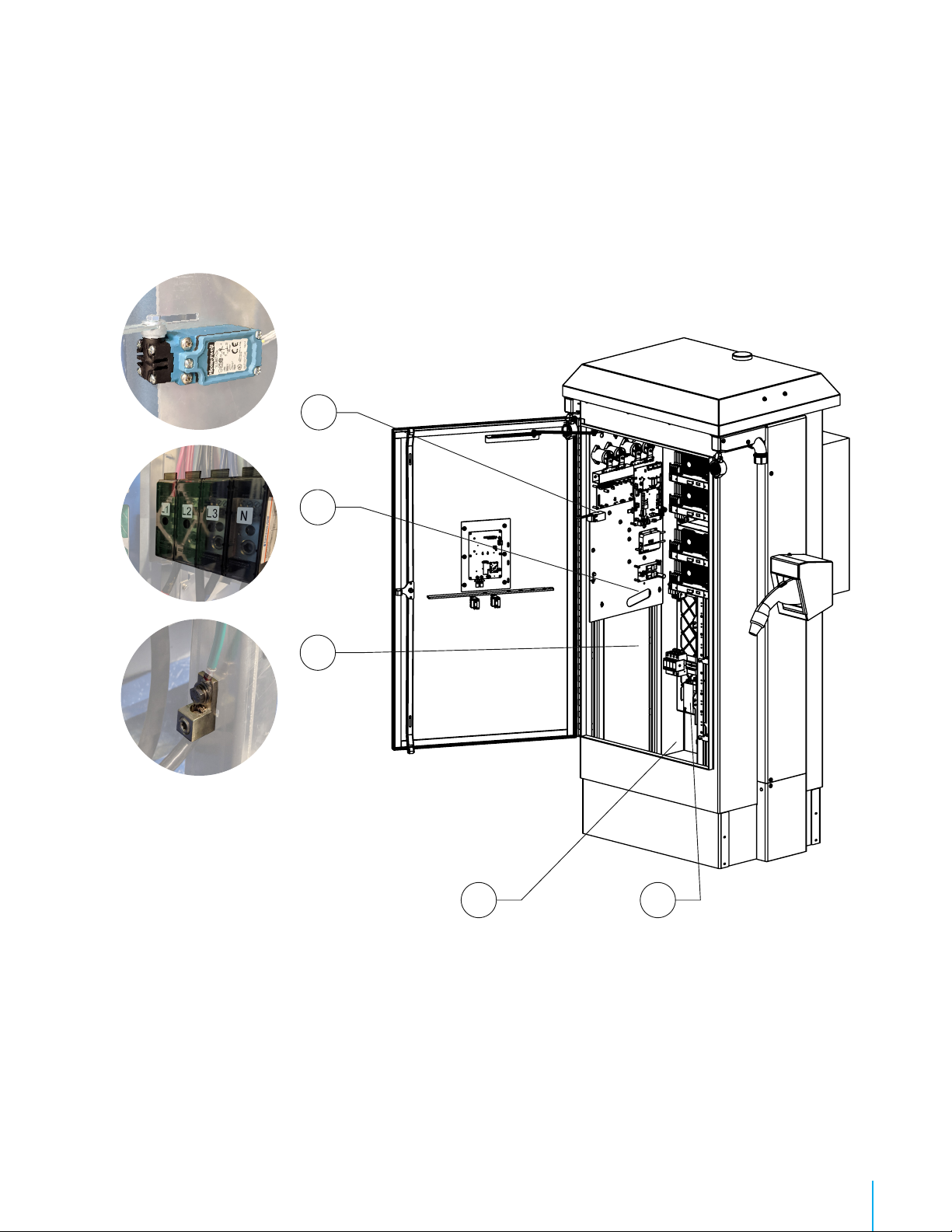
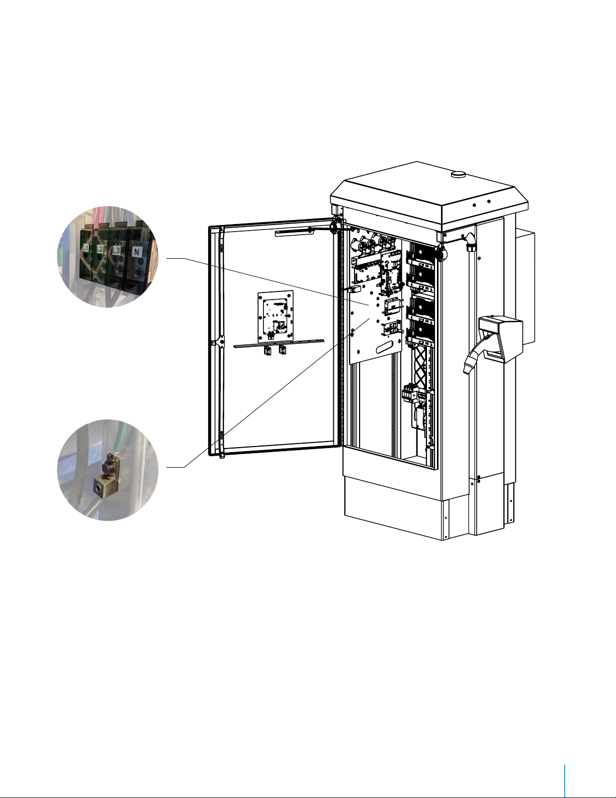
Interior preview of the station
A : Power cable access
B : Three-phase and neutral terminals
C : Door switch
D : AC/DC conversion modules
E : Grounding terminal
A
D
E
B
C
SmartDC
Installation Guide
9
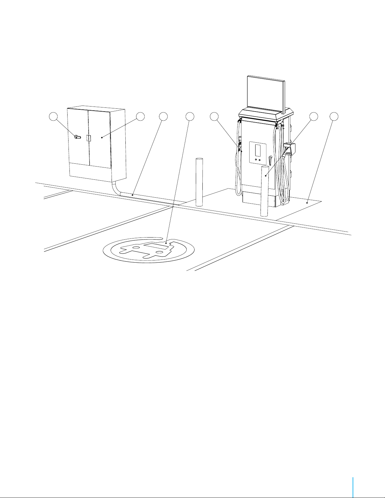
Typical installation
A : Electrical equipment cabinet (metering, protection and distribution)
B : Power cable (three-phase 480 Y/277 Volts @ 100 A or 200 A + NEUTRAL + GROUND)
C : SmartDC Station
D : Master disconnect switch (must be visible from the station)
E : Parking space for the electric vehicle
F : Protective bollard
G : Concrete Slab
When a step down or a step up transformer is necessary to convert the available voltage to the required 480 Volts nominal,
a Y auto transformer, a ./Y transformer, or a Y/Y transformer is suitable.
WARNING: Open Delta Type autotransformer and transformers having their primary configured as « Open Delta » are proscribed.
The product offers mounting congurations that support ADA compliance. Validate with local authorities on how to design the site.
DABE C FG

SmartDC
Installation Guide
10
Site preparation
1. The station must be installed on a concrete slab.
2. The surface of the concrete slab must be large enough to install both the station, and the protective bollards, and still have enough space for
users to circulate. The above figure shows the ideal dimensions and distances to respect.
3. The ground underneath the slab must be properly drained and stabilized (as required), so that it is not affected by freezing.
4. An electric conduit compliant with local regulations of appropriate diameter (based on the electric wire gauge) must bring the electric cable
under the station’s perimeter, preferably in the forward-left zone under the station’s perimeter.
NOTE: Wiring conduit must be sealed to prevent moisture ingress
IMPORTANT: A clearance of at least 16 inches must be maintained between the enclosure's back and a rear facing wall
or any vertical obstacle.
MIN
MIN
MIN
Option 1:
Bollards on concrete slab
Option 2:
Bollards next to concrete slab

SmartDC
Installation Guide
11
Base Installation on concrete slab
1. Use stainless steel 3/8 in concrete wedge anchors (not included).
2. Drill holes in the concrete slab of diameter and depth appropriate for the anchors, according to the base’s mounting holes,
as illustrated.
3. Once the holes are drilled, place the base and screw in the anchors.
6X
SmartDC
Installation Guide
12
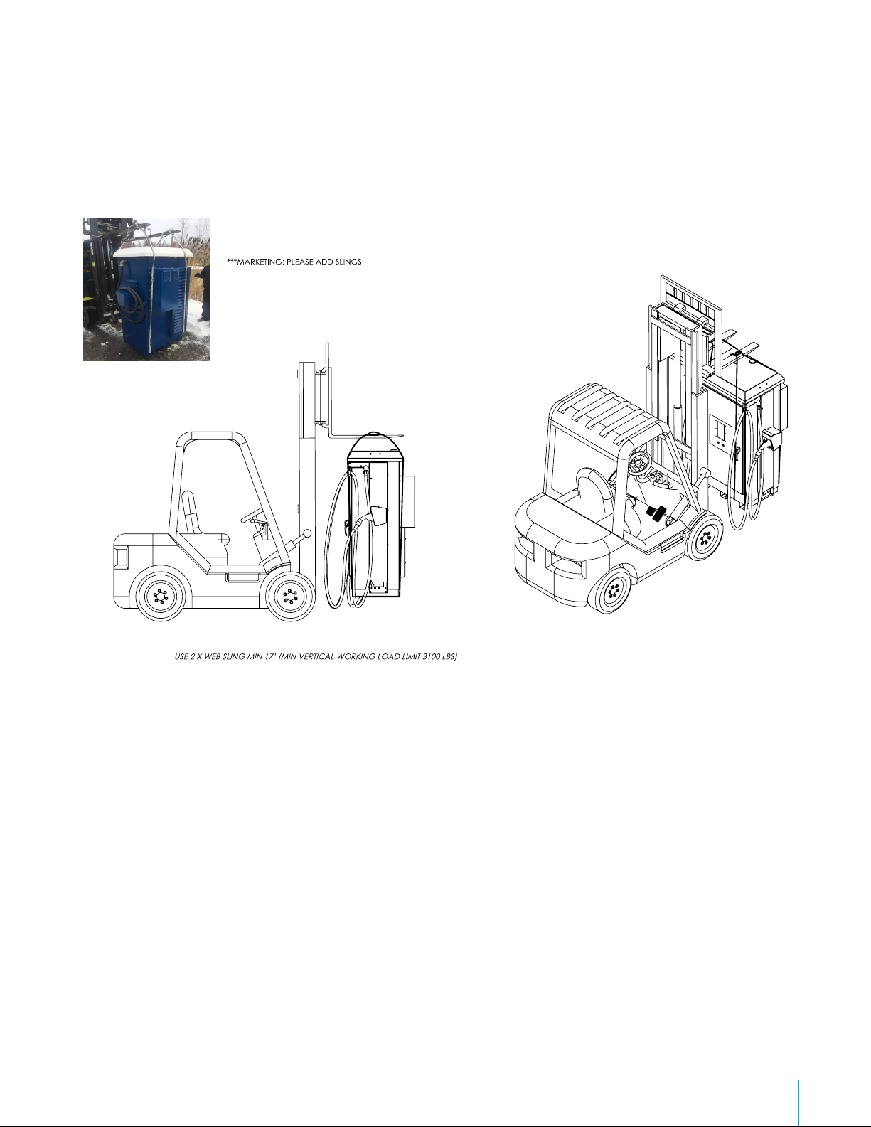
Lifting and handling of the station
NOTE:
AS SHOWN ON PICTURE

SmartDC
Installation Guide
13
Installing the station onto the base
1. Remove the access plate to allow the passage of the power cable.
2. Place the station onto its base, making sure to pass the power cable through the access hole.
3. Punch a hole in the access plate of an appropriate diameter for the cable connector.
4. Install the cable connector onto the access plate.
5. Insert the power cable into the cable connector.
6. Put the access plate back in place.
Power cable access plate:
To ensure good performance of the
charger, ensure the access plate is put
back in place
SmartDC
Installation Guide
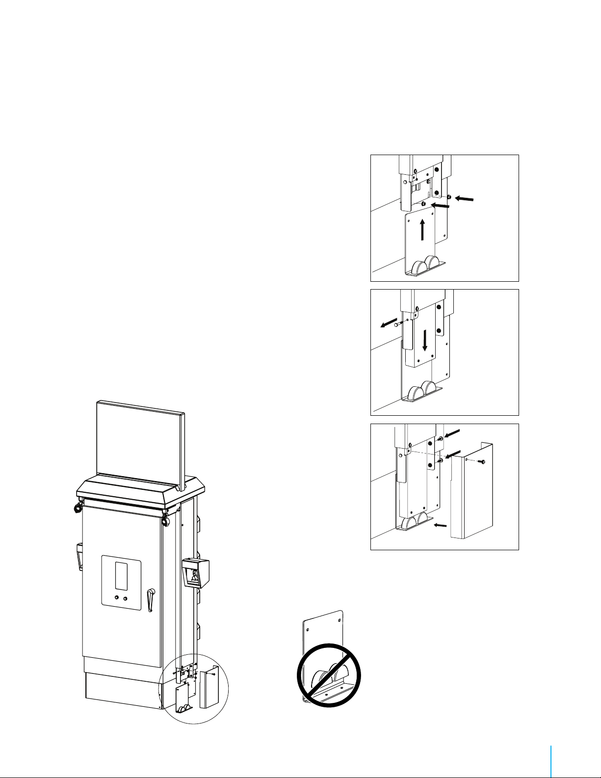
14
1. Install the aluminum plate with the rubber stoppers and secure it with
the bolts. Ensure the aluminum plate is resting firmly on the ground.
2. Remove the security screw and release the counterweight.
CAUTION: DO NOT put your hands or fingers between
the rubber stoppers and the counterweight.
3. Place the cover over the counterweight system.
Installing the counterweight (optional)
1
2
3
IMPORTANT: DO NOT remove the
rubber stoppers from the aluminum
plate, since this may result in
damage to the charging station.

SmartDC
Installation Guide
15
1. Align the panel with the 4 holes on top of the charging station.
2. Screw the 4 bolts to secure the panel.
NOTE: If there are any issues while installing the Top Sign, please contact AddEnergie support.
Installing the top sign
SmartDC
Installation Guide
16
1. Connect the three phase-conductors and the neutral conductor into the power terminal with a torque of 500 Lb-In.
2. Connect the GROUND into the grounding terminal with a torque of 50 Lb-In.
NOTE: Connectors are compatible with copper and aluminum wire.
Electrical connections to the station
A B C

SmartDC
Installation Guide
17
Station start-up
Before turning the station on:
1. The electrician must ensure that the electrical installation conforms to the applicable electrical code.
2. The circuit breakers inside the charging station must be in the “ON” position.
As the station is being turned on:
1. The electrician must verify that the station’s three-phase 480 Y/277 V voltage is within specications.
Once the station is on:
1. Close and lock the charging station’s casing door.
Putting the station into service:
1. After the station has been turned on, messages will appear on the screen in front of the station, conrming that it is now
functional.
2. The station will then attempt to communicate with the AddÉnergie servers.
3. Once the station and gateway are powered on, please communicate with the technical support of AddÉnergie to complete
the conguration: (877) 505-2674 ext. 203.

SmartDC
Installation Guide
18
Care and maintenance of the station
THIS STATION REQUIRES YEARLY MAINTENANCE TO ENSURE PROPER OPERATION.
MAINTENANCE MUST BE PERFORMED BY ADDÉNERGIE.
It consists of:
1. Cleaning or replacing the cooling system lters.
*It is important to maintain proper airflow inside the station to adequately cool the power modules.
2. Inspecting the critical components of the station.
*cables/connectors, power modules, etc.
We recommend that you increase the frequency of station maintenance to 4 times a year in the following
situations:
• When the station is installed in a dusty area.
• When the station’s average cumulative use exceeds 3 hours of charging per day.

SmartDC
Installation Guide
19

Installation or commissioning questions:
(877) 505-2674 ext. 203
AddÉnergie Technologies Inc.
Eastern Office: 2800 Louis-Lumière, Suite 100, Quebec (QC) G1P 0A4 CANADA
Central Office: 7420 Airport Road, Mississauga (ON) L4T 4E5 CANADA
United-States Office: 75 South Clinton Ave. Suite 510, Rochester (New-York), 14604, USA
© 2019 Services FLO Inc. All Rights Reserved. Services FLO Inc reserves the right to alter product offerings and specications at any time without notice and is not responsible for typographical or graphical errors that may appear in this document. All pictures shown are for illustration purposes only. Actual product may vary due to product enhancements.
Contact Us
T. 1 877 505-2674
F. 855 505-2674
flo.com flo.com
Table of contents
Other Flo Automobile Accessories manuals


