DAVIS DriveRight User manual

I
NSTALLATION
M
ANUAL
Product #’s: 8140, 8143, 8146, 8150

1
1.
C
ONTENTS
OF
P
ACKAGE
1. DriveRight display
2. Battery (CR123 3V Lithium)
3. Coiled cable extension
4. Harness cable
5. Visor clip
6. Mounting bracket
7. 6-32 x 1/2” flat head machine screw (3)
8. #6 x 1/2” flat head self-tapping screw (3)
9. #6 split lock washer (6)
10. #6 flat washer (6)
11. 6-32 nut (3)
12. Right angle adapter bracket
13. #6 x 1/2” pan head self-tapping screw (3)
14. Double-sided foam tape (2 each)
15. VELCRO
®
tape (2 pair)
16. Red +12v wire with fuseholder (22 AWG)
17. Fuse (3AG 1-1/4” x 1/4”, .25A, SLO-BLO)
18. Black ground wire (22 AWG)
19. Spade terminal (2)
20. In-line splice (3)
21. Butt splice (26-22AWG or 24-20AWG) (5)
22. Magnet
23. Magnet mount
24. Large tie wrap (2)
25. Speed sensor with leads
26. 1/2” brass hex nut (2)
27. 3/8” flat washer
28. 3/8” internal tooth lock washer
29. Sensor mounting bracket
30. Support bracket
31. #14 x 3/4” self-tapping screw (4)
32. 1/4-20 x 3/4” hex head machine screw
(5)
33. 1/4” split lock washer (5)
34. 1/4” flat washer (5)
35. 1/4“-20 nut (5)
36. Split flexible tubing
37. Small tie wraps (8)
Figure 1:DriveRight Parts

2
2.
I
NTRODUCTION
The Davis DriveRight™ is designed to allow straightforward installation. The spe-
cific details of installation vary by vehicle model and year. This manual provides
general instructions sufficient to guide a professional installer or knowledgeable,
experienced individual through a successful installation. Please read or at least skim
the
entire manual
before beginning the installation. Read and understand each step
thoroughly before starting that step. Your DriveRight includes a limited number of
extra parts. In this manual, parts will be referred to by their item numbers shown in
Figure 1.
WARNING:
The magnet supplied with the DriveRight is extremely strong and will de-magnetize
ATM cards, credit cards, etc., if brought in contact. It may also affect other sensitive
electronic equipment.
P
ROFESSIONAL
VS
. D
O
-I
T
-Y
OURSELF
I
NSTALLATION
Davis Instruments strongly recommends that the DriveRight be installed by ASE
(Automotive Service Excellence) certified technicians or professional automotive
mechanics. As with any installation of an automotive accessory, the installer must
make a series of decisions, in this case decisions such as where and how the sensor
and brackets are mounted, where holes are drilled, how wires are routed, where to
locate unswitched +12V and ground and so on. These decisions are best made by a
knowledgeable and experienced professional. Poor decisions may damage your vehi-
cle or cause accidents or injuries.
If you select professional installation, use the procedure described in “Initial Test”
on page 18 to verify the work done.
WARNING:
Working beneath your vehicle and installing the DriveRight may be hazardous.
Improper installation may damage your vehicle and cause accidents and/or injuries. If
you are uneasy about installing your unit please have a qualified professional complete
the installation. Davis specifically disclaims any liability for injury or loss resulting
from the installation or use of the DriveRight.
G
ETTING
R
EADY
Before installing your DriveRight:
• You may need to raise the vehicle in order for you to work under it. Always use
safety stands when working on or under any vehicle that is supported by only a
jack.
• You may need the following tools or equivalent. Additional tools may be
required depending on your specific installation.
• drill and drill bits, 1/8” to 5/16” (3 to 8mm)
• multimeter and/or test light
• hacksaw
• adjustable wrenches
• vise
• metal forming tools
• crimp tools
• wire cutter

3
• wire stripper
• various screwdrivers
• pliers
Figure 2: Typical Installation

4
3.
P
LANNING
Y
OUR
I
NSTALLATION
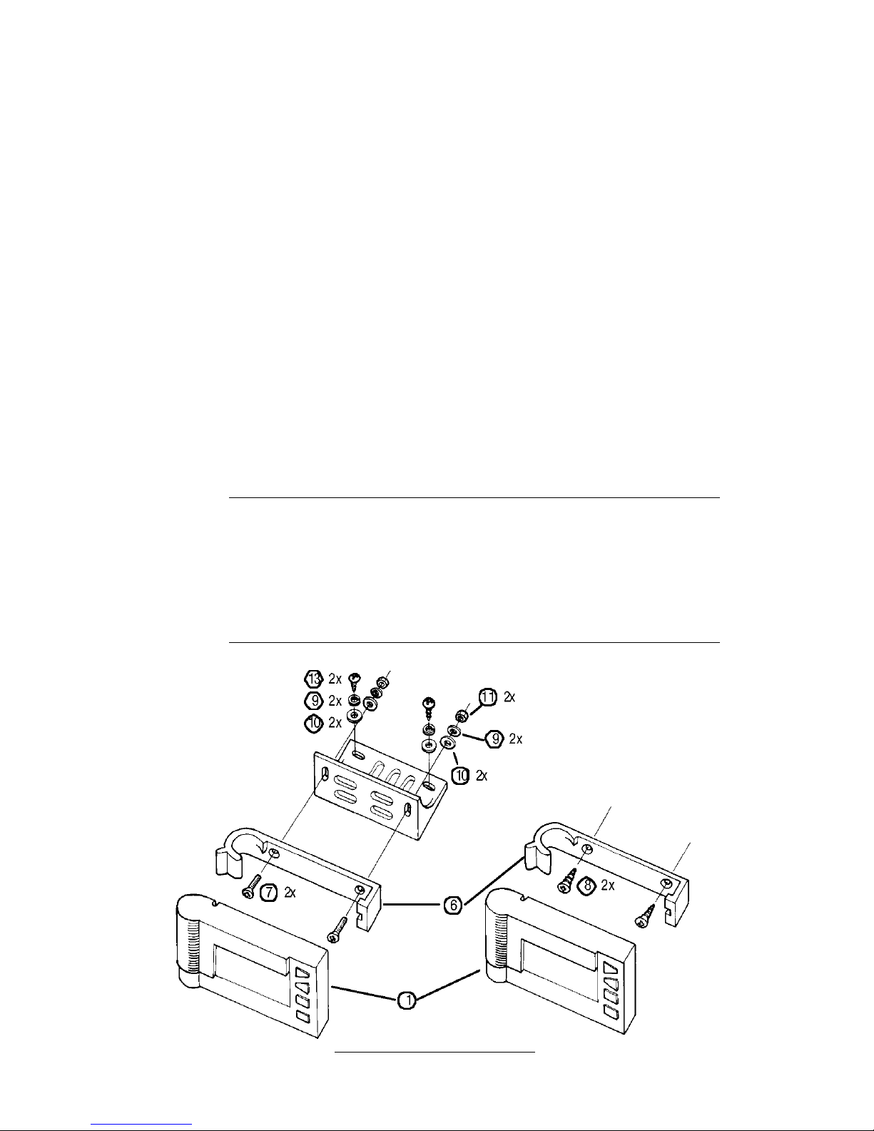
Figure 2 illustrates the installation of the DriveRight. The sensor, sensor magnet
and associated brackets mount underneath your vehicle. Figure 12 on page 11 is a
sketch of a typical rear wheel drive sensor installation while Figure 17 on page 13 is
a sketch of a typical front wheel drive sensor installation. The sensor leads run
under the vehicle and into the vehicle cabin where they connect to the DriveRight
display. The DriveRight display also requires unswitched +12V and ground connec-
tions to your vehicle’s electrical system.
Before you begin the actual hands-on installation of your DriveRight, please plan
out your installation by thinking through the following points. This will save you
time, frustration, and parts.
• Determine how and where you want to mount the DriveRight display within the
vehicle cabin.
NOTE:
Safe driving requires that the driver’s attention be focused on the road. Please install
your DriveRight in a location which minimizes distractions to the driver.
• Find a single point in the vehicle cabin where you can bring together the leads
of the harness cable, the sensor leads, and the +12V and ground wires.
• Determine how you will route the harness cable to the DriveRight display.
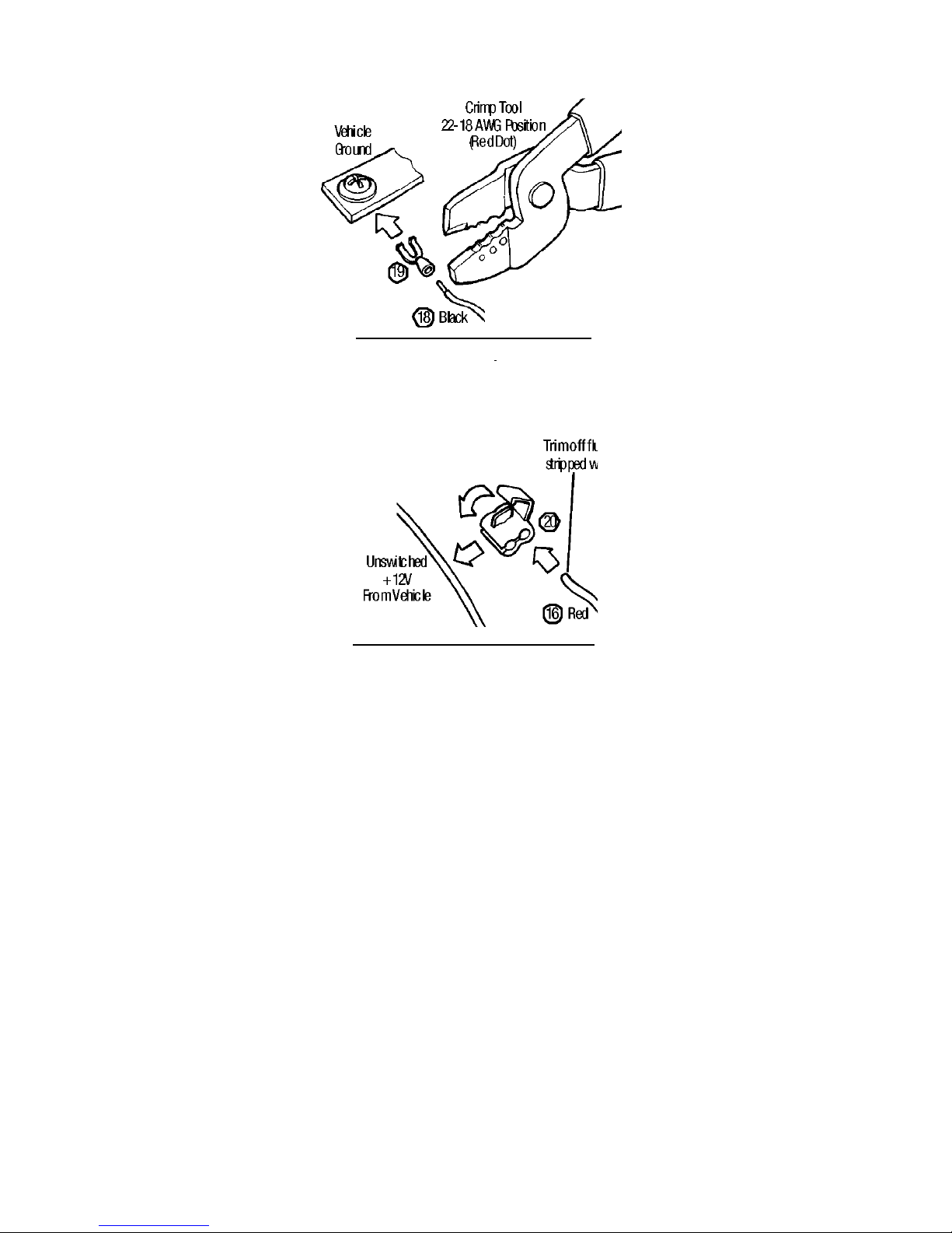
• Locate your fusebox and find a source of UNSWITCHED +12V NOT USED FOR
SAFETY RELATED EQUIPMENT.
NOTE:
“Unswitched +12V” means +12V not switched off by the ignition key. The
DriveRight consumes negligible power (nominally, 5mA) and will not run down
your vehicle’s battery. The lithium 3.0V battery inside the DriveRight is not
rechargeable and is not charged by the vehicle’s battery.
• Locate a ground point to attach a ground wire spade terminal.
• Locate a feedthrough into the vehicle cabin through which you can bring the
two sensor leads and the +12V and ground wires if your fusebox is in your
engine compartment.
• IF YOU HAVE A FRONT WHEEL DRIVE VEHICLE, decide whether you will place the
sensor magnet on either the left or right side in-board constant velocity (CV)
joint hub.
• IF YOU HAVE A REAR WHEEL DRIVE VEHICLE, decide where on the driveshaft
within 12” (30cm) of the transmission you will place the sensor magnet.
• Decide how you will attach the brackets so that the sensor is within 3/8” - 5/8”
(10-16mm) of the magnet. How will you form the brackets to fit? What holes
will you use or drill to mount the bracket? Do these holes pierce the vehicle
floor? Where? (DO NOT USE FLUID RETAINING BOLTS AS MOUNTING POINTS.)
• Decide how you will route the wires from the sensor to a feedthru into the
vehicle cabin.
• THE WIRES SHOULD BE ROUTED AT LEAST 12” (30CM) AWAY FROM SPARKPLUG
WIRES, THE COIL, AND THE ALTERNATOR. AVOID LOOPS, COILS, AND FOLDS
SHOULD TO PREVENT UNWANTED INTERFERENCE THAT MIGHT RESULT IN
ERRONEOUS READINGS.

5
Step 1. D
ISPLAY
M
OUNTING
O
PTIONS
The DriveRight comes with the hardware necessary for a variety of display mount-
ing options. The long harness cable (4) included with the DriveRight allows you to
install the display where you want it. You may, at your option, use the coiled cable
extension (3) for even greater convenience.
• Use the visor clip (5) to mount your display on a visor or door pocket. Install the
clip on the top or bottom of the display to orient the display as you wish (Figure
4). Push the clip in until the 3rd bump engages.
• Mount your display to the dash or center console. Choose a location and decide
how you want to mount the display: directly to the surface or using the mounting
bracket (6) and right angle adapter bracket (12). Then, decide how you want to
attach the display or the brackets: using VELCRO tape (15), double-sided foam
tape (14), or screws. Apply the two adhesive-backed loop tapes to the flats on the
back of the display (Figure 5) or to the back of the brackets. With the hook tapes
attached to the loop tapes, press adhesive backing of the hook tape onto your
selected mounting surface. Do not separate hook and loop tape for at least 24
hours after applying. Attach the mounting bracket to the right angle adaptor
bracket (12) with hardware provided as needed (Figure3). Mount the reversible
right angle adaptor bracket to desired location with hardware provided. Apply the
double-sided foam tape to mount the brackets if desired.
NOTE:
For best results with foam tape or VELCRO, apply adhesive at room temperature of
68˚F (20˚C) or higher. Surface should be clean, dry and free of oils. Use clean wip-
ing materials with a cleaner appropriate for your vehicle’s interior to free surface of
contaminates and allow to dry. Peel release liner from back of tape and apply. (Take
care not to touch the adhesive with your fingers.) If adhesive must be applied at tem-
peratures lower than 68˚F (20˚C), warm substrate and the tape to elevate tempera-
ture prior to applying. This may help the bond cure. Allow 24 hours for full cure
before loading or cycling.
Figure 3:Bracket Mounting Options

6
Figure 4:Using the Visor Clip
Figure 5: Applying VELCRO
15 2x
Loops
Hooks

7
Step 2. +12V P
OWER
AND
G
ROUND
C
ONNECTIONS
NOTE:
Thinking ahead...In Step 5, you will bring the sensor leads, +12V wire, and ground wire to
a single point of your choice under the dash and connect them to the display harness cable.
Choose this single point now. The sensor leads must be led into the vehicle cabin. Usually
you can use an existing feedthru in the firewall. If your fusebox is in the engine compart-
ment then you may also need a feedthru to bring the +12V and ground wires through into
the vehicle cabin.
The DriveRight requires an
unswitched
+12V connection to your vehicle and a
ground connection to the vehicle chassis. These connections are often most easily
made at your vehicle’s fusebox. A direct connection in your fusebox is best - some
vehicles have extra slots for accessories such as the DriveRight. You may need to buy
the proper termination for use with your vehicle’s fusebox - consult your dealer or
local auto parts store. Attach the termination or connector to the end of the red
+12V wire with fuseholder (16) and insert into your fusebox. Otherwise select an
unswitched
wire exiting the fusebox
that does not involve safety-related equip-
ment such as headlights, brakes and so on
. Possible candidate wires may include
the wires used for the cigarette lighter, dome light (before the switch), glove com-
partment light, clock, tail gate light and other convenience functions. The wire
used should be 22-18AWG or have the same diameter as the red +12V wire with
fuseholder. Use the in-line splice (20) to make the connection to the red +12V wire
with fuseholder (Figure 9). Trim off flush the stripped portion of the red wire. The
fuseholder should be in the vehicle cabin.
Figure 6:Making Unswitched +12V and Ground Connection Within Vehicle Cabin

8
A ground connection may be made be inserting the spade terminal (19) under the
head of a screw threaded into the vehicle chassis (Figure 8). Use a multimeter to
verify the ground connection to vehicle chassis. The fusebox mounting screws are
candidate connections. If a screw is not convenient, locate a ground wire that is
22-18AWG or has the same diameter as the black ground wire. Use an in-line splice
(20) to make the connection to the black ground wire.
Figure 7:Making Unswitched +12V and Ground Connection Outside Vehicle Cabin

9
Figure 8:Crimping the Spade Terminal
:
Figure 9:Splicing for Unswitched +12V

10
Step 3. S
ENSOR
I
NSTALLATION
The sensor installation requires mounting a magnet on the drive shaft of a rear
wheel drive vehicle or on the in-board CV joint hub of a front wheel drive vehicle.
The reed switch sensor (25) is mounted on a bracket opposite to the magnet rotat-
ing on the drive shaft or in-board CV joint hub. The sensor detects the magnet as it
passes. The gap between the magnet mount and sensor must be 3/8” - 5/8”
(10-16mm) (Figure 11 and Figure 15). There should be a clearance zone of at least
3/4” (19mm) above the drive shaft or in-board CV joint hub where the magnet is
mounted (Figure 11 and Figure 15).
R
EAR
W
HEEL
D
RIVE
NOTE:
Thinking ahead...Consider the mounting locations carefully. Are the attachment points
strong enough? What is behind any surface you want to drill into? Do not drill into your gas
tank or foot wells in the vehicle cabin or any location where wires might be present. Check
both sides of the surface before you drill.
A typical rear wheel drive installation is shown in Figure 12. Select a location on the
drive shaft within 12 inches (30cm) of the universal joint to account for vehicle sus-
pension movement while driving (Figure 10). Install the magnet (22) in its mount
(23) using the large tie wrap (24) as shown in Figure 13. Loosely cinch the large tie
wrap around the drive shaft, with the magnet mount oriented as shown, so you can
adjust its final position after the sensor is installed. Do not cinch tight the tie wrap.
Figure 10:Positioning the Sensor (Rear Wheel Drive)
Figure 11:Determining Proper Clearances and Gap (Rear Wheel Drive)

11
Figure 12: Typical Installation (Rear Wheel Drive)
Figure 13:Installing the Magnet (Rear Wheel Drive)

12
F
RONT
W
HEEL
D
RIVE
NOTE:
Thinking ahead...Choose the in-board CV joint hub you want to use by looking at how you
can mount the sensor and how in Step 5 you will route the wires into vehicle cabin . Con-
sider where feedthrus are and how you will make the connections in Step 6.
Select an in-board CV joint hub and install the magnet (22) in its mount (23) using
the large tie wrap (24) as shown in Figure 16. Loosely cinch the large tie wrap
around the CV joint, with the magnet mount oriented as shown, so you can adjust
its final position after the sensor is installed. Do not overlap boot. Do not cinch tie
wrap. Choose mounting locations for the sensor mounting bracket and support
bracket on the transaxle/engine assembly (Figure 17). Do not mount the bracket on
the vehicle chassis because of engine torque. Do not use fluid retaining bolts to
retian the brackets.
Figure 14:Positioning the Sensor (Front Wheel Drive)
Figure 15:Determining Proper Clearances and Gap (Front Wheel Drive)
Figure 16:Installing the Magnet (Front Wheel Drive)

13
Figure 17: Typical Installation (Front Wheel Drive,Engine Mount)

14
Step 4. S
ENSOR
B
RACKET
I
NSTALLATION
(C
ONTINUED
)
The instructions below describe an optimal sensor bracket assembly. Due to the
variations in individual cars, you will need to adapt these instructions to fit the sen-
sor bracket into whatever situation exists. As you do so, it is vital to insure that
THE SENSOR END PROTRUDES 3/4” (19mm) FROM THE SENSOR
MOUNTING BRACKET. See Figure 11 on page 10 or Figure 15 on page 12. In
addition, the brackets must not protrude below other parts on the vehicle under-
body.
NOTE:
At low speeds, excessive vehicle vibrations can cause erroneous readings.
R
EAR
W
HEEL
D
RIVE
Choose mounting locations for the sensor mounting bracket (29) and support
bracket (30). The support bracket reinforces the sensor mounting bracket against
vibration. Do not mount the brackets as shown in Figure 19. After installing the
brackets for the proper gap between the sensor tip and the magnet mount, adjust
the large tie wrap so that the magnet passes opposite the end of the sensor. Cinch tie
wrap tight against drive shaft. Check the alignment of the magnet mount with end
of sensor by spinning tires if possible.
F
RONT
W
HEEL
D
RIVE
The support bracket reinforces the sensor mounting bracket against vibration. Do
not mount the brackets as shown in Figure 19. After installing the brackets for the
proper gap, adjust the large tie wrap so that the magnet passes opposite the end of
the sensor. Cinch tie wrap tight against CV joint hub. Check the alignment of the
magnet mount with end of sensor by spinning tires if possible.
Figure 18:Sensor Bracket Assembly

15
Figure 19: Wrong Way To Use Brackets
Step 5. W
IRE
R
OUTING
Use the split flexible tubing (36) to protect the sensor leads from sensor up into the
vehicle cabin. Use the small tie wraps (37) to hold the leads against the underbody
of your vehicle. The tubing can be cut into pieces and used where the wires may rub
against sharp points or edges and where the leads are tie wrapped to the underbody.
Tubing can also be used where the leads are particularly exposed. If a vehicle wire
bundle is readily accessible, route the sensor leads along this wire bundle. The sen-
sor leads should be routed at least 12” (30 cm) away from sparkplug wires, the coil,
and the alternator. Loops, coils, and folds should be avoided in order to avoid creat-
ing unwanted interference that might result in erroneous readings.
Figure 20:Protecting the Wires

16
Step 6. W
IRE
C
ONNECTIONS
Make final connections (Figure 21). Use the butt splices (21) to connect the white
sensor lead to harness cable white wire, the black sensor lead to harness cable black
wire, and the red +12V wire w/ fuseholder to harness cable red wire (Figure 22).
Stripped wire ends should be 3/16”- 1/4” (5-6 mm). Use an in-line splice to con-
nect the black ground wire to the black sensor lead near the butt splice (Figure 23).
Install fuse (17) in fuseholder. Use a small tie wrap to secure and protect the con-
nections under the dash.
CAUTION:
If the connections are on the driver’s side, make sure the wires can not become entangled
in the vehicle pedals or driver’s feet.
Figure 21:Making Final Connections

17
Figure 22:Crimping the Butt Connectors
Figure 23:Splicing Ground Together

18
Step 7. I
NITIAL
T
EST
To check the installation of the DriveRight, follow the test procedure below.
NOTE:
It is not necessary to enter a code in order to perform this test. DO NOT ENTER A CODE
UNTIL YOU READ THE USER’S MANUAL.
1. Insert the battery (2) into the display as shown in Figure 24. (If your battery is
already installed, you may need to press MODE to “wake up” the unit.)
Figure 24:Installing the Battery
The screen you should see is the current readings screen. The word “BAT”
should appear in the lower left corner, indicating that the unit is operating on
battery power.
Figure 25:Battery Indicator (Lower Left of Screen)
2. Press and hold MODE for 3-5 seconds until the last correct code screen appears.
If you have already used the display, you may see the tamper time screen instead.
If so press
MODE
once to display the last correct code screen.
Figure 26:Last Correct Code Screen

19
3. With the ignition off, insert the DriveRight display cable into the harness cable
connector and lock the connectors. To do this, you will need to grasp the display
cable just behind the plastic sheath covering the connector, as shown below.
Push the display cable in until it locks into place.
Figure 27:Connecting the Display Cable to the Harness Cable
NOTE:
To disconnect the two cables, hold the plastic sheath on the display cable, as shown
below. Pull back until the two connectors separate.
Figure 28:Disconnecting the Display Cable and the Harness Cable
When the two cables are connected, the “BAT” should disappear, indicating that
the unit is drawing power from the vehicle’s battery. A dot may appear to the
right of where BAT was. This dot will be used to verify the magnet placement in
the next step.
Other manuals for DriveRight
1
This manual suits for next models
4
Table of contents
Other DAVIS Automobile Accessories manuals
Popular Automobile Accessories manuals by other brands

Connects2
Connects2 CAM-MB2-AD instruction manual

Thule
Thule 1723 instructions

Yakima
Yakima ROC 4 manual

American muscle
American muscle 8793 installation instructions

Metra Electronics
Metra Electronics 95-5818 installation instructions

RITE-HITE
RITE-HITE Genisys GWC-1000 Installation/Service/Owner's Manual