Flo SmartTWO User manual

SmartTWO
Installation Guide
TM

2
Split Phase 120/240 VAC Supply or 3 phase 120/208 VAC C (must be protected by a 40 A
fuse or circuit breaker) Both lines must have 120V between ground.
Voltage supply must be grounded.
Require 2 lines and 1 ground connection. Neutral is not used. (Refer to Figure 1 and
Figure 2).
Maximum output power: 7.2kW @ 240 VAC or 6.3KW @ 208 VAC
Built-in protection against overvoltage conditions and leakage current to ground
Connect the power supply of the EVSE with caliber 2 to 8 copper or aluminium
conductors
Any EVSE part alteration will automatically void the warranty.
Install the Communication Gateway prior to the Commissioning of the Station
The Communication Gateway is the property of AddÉnergie. Fees will be charged if
the Gateway is damaged or lost.
IMPORTANT ELEMENTS TO CONSIDER WHEN INSTALLING THE COMMUNICATION
GATEWAY:
•An Outdoor installation is recommended. The Customer must provide a waterproof
PVC box and install it less than 50 meters (164ft.) from the stations.
•Never use a GFCI outlet to power the Communication Gateway.
Contact us when the Communication Gateway is installed to validate the signal levels
and activate Commissioning or for any other questions: 1 855 543 8356
IMPORTANT
Fig. 1 Fig. 2
N eut ra l
(N.C)
120VAC
240VAC
L1
L2
Spl it P hase 120/240 VAC Supply
Charging
Station
120VAC
GND
GND
A
BC
208 VAC
120VAC
3 phase 120/208 VAC Suppl y
GND
Charging
Station
L1
L2
(N.C) N eut ra l
GND

3
Table of Contents
Specifications .................................. 4
Maintenance and Safety .......................... 5
Configurations .................................. 6
Wall Mount .................................... 7
Connection ................................... 10
Front Panel and Base Cover Installation.............. 11
Station Heads Installation on the Bases.............. 12
Installation of the Panel on the Charging Head. ........ 13
Preliminary Tests and Commissioning ............... 14
Copyright and Liability . . . . . . . . . . . . . . . . . . . . . . . . . . . .15
4
Specifications
Model: SmartTWOTM
EVSE type: Level 2
Output connector: SAE J1172 compliant
Split Phase 120/240 VAC Supply or 3 phase 120/208 VAC (must be protected by a 40 A fuse
or circuit breaker) Maximum output power: 7.2kW @ 240 VAC or 6.3KW @ 208 VAC
Built-in protection against overvoltage conditions and leakage current to ground
Ingress Protection rating: 3R enclosure type, suitable for outdoor use
Shipping weight: Approximately 30kg for the single pedestal configuration
Patent: US 9,421,878B2
Security standard compliance:
• CSA C22.2 No. 0-10 General Requirements – Canadian Electrical code, part II
• CSA 281.1-12/UL2231-1 Standard for safety for personnel protection systems for
electrical vehicle
(EV) supply circuits: General requirements
• CSA 281.2-12/UL2231-2 Standard for safety for personnel protection systems for
electric vehicle (EV) supply circuits: Particular requirements for protection devices
for use in charging systems
• CSA C22.2 No. 280-13/UL2594 (1st edition) Electric vehicle supply equipment
(EVSE)
• Supported communication protocols: ONP and OCPP
This product is approved by the California Type Evaluation Program
Electrical standard compliance: Certified ENERGY STAR® 1.2
NOTE: The SmartTWO-M is not certified ENERGY STAR® 1.2.
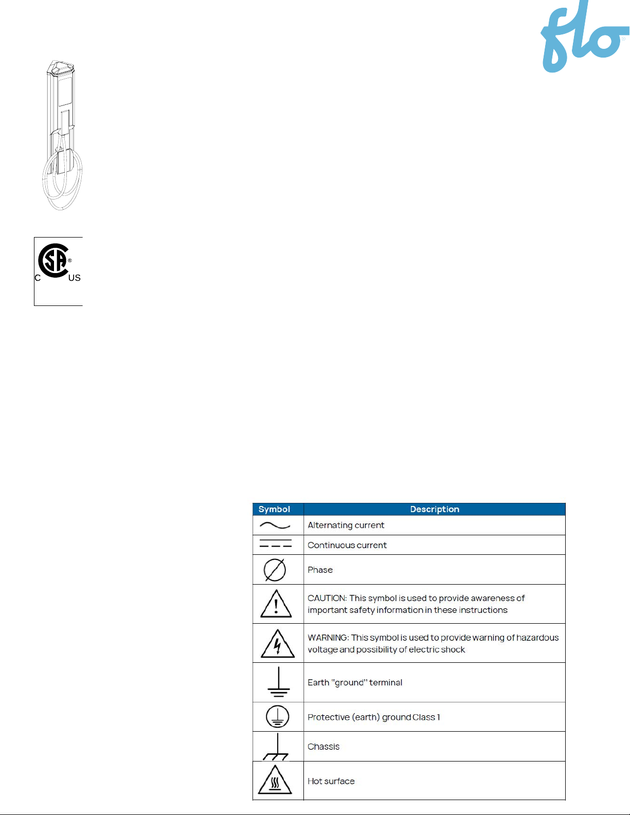
254081
Product Symbols
The following symbols appear on the station and in this guide:

5
Maintenance and Safety
IMPORTANT SAFETY INSTRUCTIONS - PLEASE DO NOT DISCARD
THESE INSTRUCTIONS
Carefully read this guide before installing the EVSE
1. This EVSE was designed to be wall-mounted or pole-mounted.
1.1. For the wall-mounted version, you must make sure the wall on which it will be
mounted is
strong enough, and that you use the appropriate type of anchors.
1.2. For the pole mounted version, you must make sure the pole on which it will be
mounted is strong enough, and that you use the appropriate type of tether straps.
2. Make sure with local authorities that the location where the EVSE is to be installed is
free from underground pipelines or electrical equipment, otherwise you might inflict
yourself serious injuries.
3. Connect the power supply of the EVSE with caliber 2 to 8 copper or aluminium
conductors rated for usage at a temperature of at least 75°C.
4. Grounding: to ensure the safe operation of the AddÉnergie’s EVSE, it must be
connected to a grounding circuit compliant with local regulations and installed by a
certified electrician.
5. Communicate with a certified contractor, certified electrician or trained installer to
ensure compliance with local building code, regulation such as ADA compliance, security
standards and weather conditions.
6. Any EVSE part alteration will automatically void the warranty.
7. Handle parts with care, since they can be sharp-edged. Always use safety glasses and
gloves when unpacking and installing.
8. Some parts are heavy and could cause injuries. Use proper lifting techniques and wear
safety boots at all times during installation.
9. Never insert your finger into the electric vehicle connection.
10. Never use the EVSE if the flexible power cord seems damaged or if insulation is
damaged.
11. Never use the EVSE if the main case is broken, cracked, open or damaged.
12. This EVSE was designed to be used with electric vehicles equipped with a SAE-J1772
connector.
13. This EVSE is to be used to charge vehicles that do not require a ventilated
environment during charging.
14. Replacement of the EVSE’s head, gun module, gun cable, or gun must be performed by
qualified service personnel.
15. When the case of the EVSE’s head is open, all gaskets must be replaced.
16. Do not install on or over a combustible surface.

6
Configurations
Recommended Dimensions
154cm
20cm
170cm
102cm
73cm
93cm
114cm
20cm
102cm
8.3cm
21cm
74cm
20cm
Leave a minimum of 7,6 cm (3’’)
on top of the main structure to
insert the EVSE’s head.
Leave a minimum of 7,6 cm (3’’)
on top of the main structure
to insert the EVSE’s head.
Leave a minimum of 7,6 cm (3’’)
on top of the main structure
to insert the EVSE’s head.
Pole-mounted EVSE
Pedestal EVSE
Wall-mounted EVSE
Drilling pattern
Ground

7
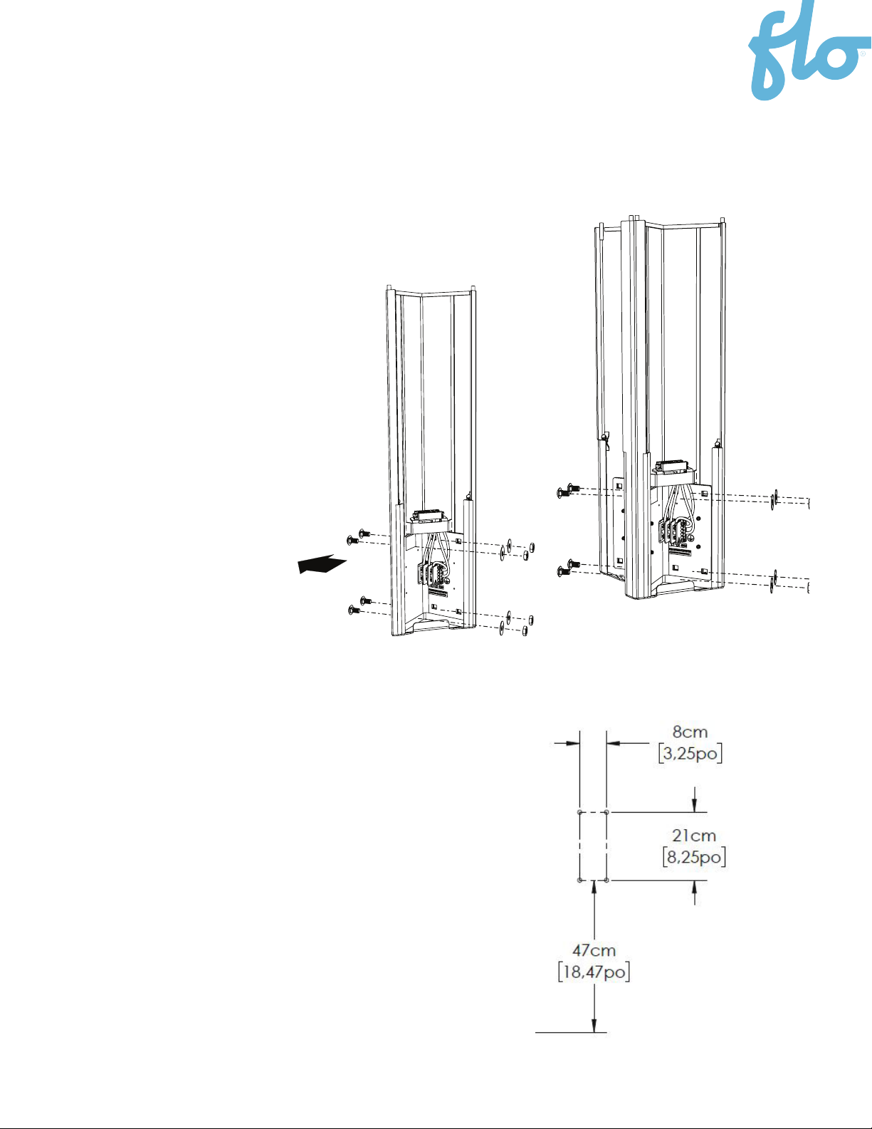
Wall Mount
Single Unit Installation
INSTRUCTIONS:
•
Make sure that the available
height is a minimum of 216cm (85”)
• If the wall requires that anchors to
be pre-installed, follow the drilling
pattern provided on right
• Install the base on the wall using the
proper type of anchors, which means
½-13 inserts and bolts for a concrete
wall, or ½ lag bolts for a wooden wall.
• Before drilling and during the
installation of the base on the wall,
make sure that everything is leveled
SPECIAL NOTES:
•
The EVSE has been assembled at the factory to point
toward the right side, assuming that it will be installed
on the left corner of the parking stall.
• To install on the right corner of the parking stall, the
nuts and bolts attaching the back of the base to its
inner frame shall be transferred from one side to the
other as shown on the pictures.
• Make sure you put both longer bolts at the position
closest to the terminal block.
2
3
No
Description
Qté
1
Structure principale
1
1
1
Panneau frontal
Couvercle du bornier
1
3
2
2
3
Nbr
Description
Qty
1
Main Structure
1
1
1
Front Panel
Block Cover
Mon
tage du côté gauch
e
Left side mounting
Mon
tage du côté droi
t
Right side mounting
SOL
GROUND
74 cm
(29’’)
21 cm
(8.25’’)
8.3 cm
(3.25’’)
Patron de perçage:
Drilling pattern:
Ground

8
Wall Mount
Double Unit Installation
For double mounting with panel holder (part number: S2-V2-
ACCSPSM-01-02), add spacers (part number: S2-V2-
ACCSPSM-01-05) between the main structures.
Utiliser des boulons plus longs
3.8 cm (1.5’’)
Use longer bolts, 3.8 cm (1.5’’)
9
• Make sure that the available height is a
minimum of 216cm (85”).
• If the wall requires that anchors to be
pre-installed, follow the drilling pattern
provided on right.
• Install the base on the wall using the
proper type of anchors, which means
½-13 inserts and bolts for a concrete
wall, or ½ lag bolts for a wooden wall.
• Before drilling and during the installation
of the base on the wall, make sure that
everything is leveled.
Wall Mount
Double Unit Installation
INSTRUCTIONS:
•Identify which sides of the main
structure must be assembled
face to face and remove their
corresponding bolts and
screwed plates.
•Place the main structures one
against the other and join
using the four (4) longest
carriage bolts you just
removed.
SOL
GROUND
74 cm
(29’’)
21 cm
(8.25’’)
8.3 cm
(3.25’’)
Patron de perçage:
Drilling pattern:
Ground
10
Installation and maintenance of this EVSE
must only be performed by a certified
electrician to ensure compliance with local
and national codes.
Requires a dedicated 40A dual
protection device (breaker or fuse).
Do not add CCID protection to the service
panel. This kind of protection is already
built into AddÉnergie’s EVSE.
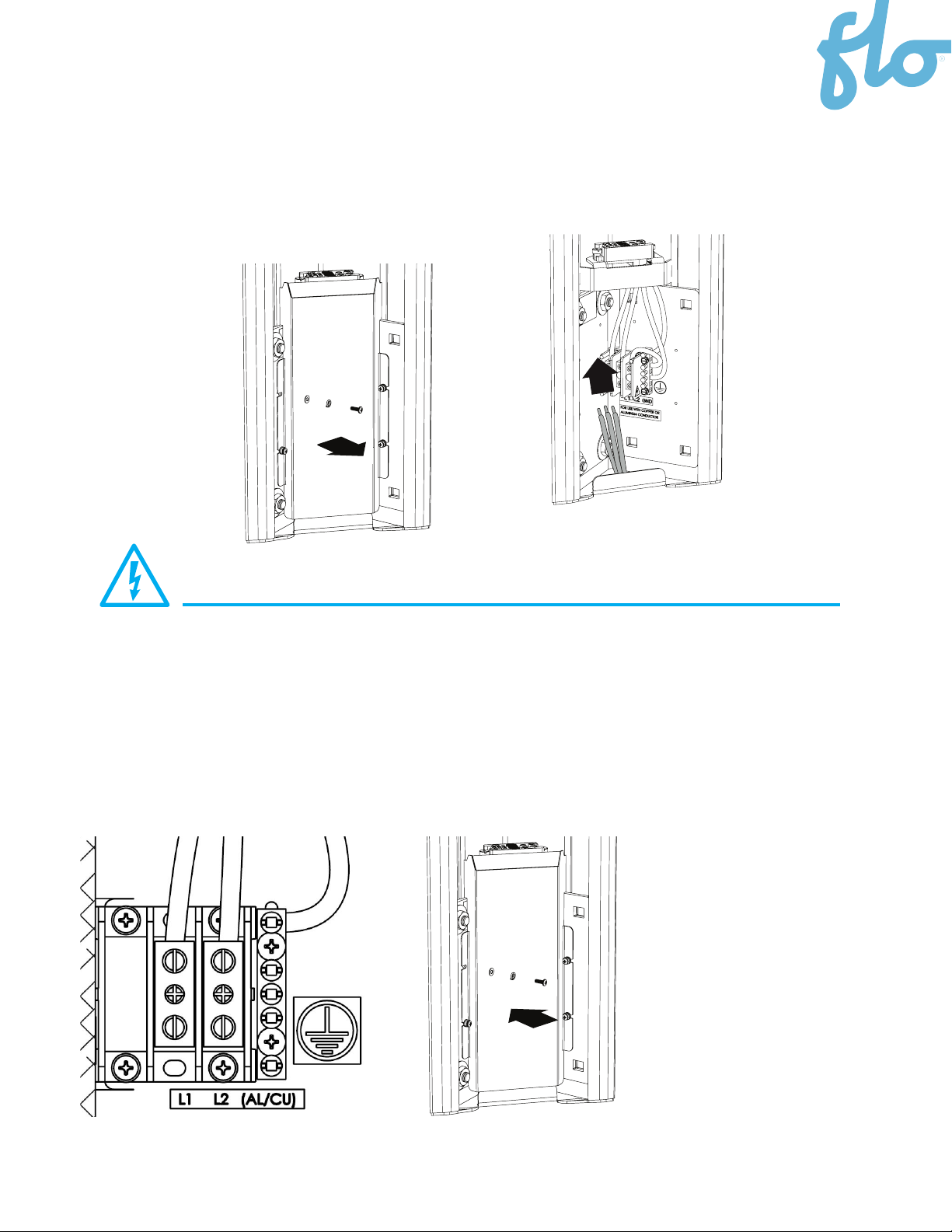
Input: 208/240VAC nominal, 60Hz, 30A
Recommended tightening torque for the block
bolts: 18Nm. Wire size of AWG 2 - 8, copper or
aluminium
Le couvercle du bornier doit
être remis en place une fois les
connexions effectuées
Reinstall the block cover once
all connections are made.
IMPORTANT
Electrical Connections
Remove the block cover.
Insert the wires from the bottom of the base and proceed with the connection as
shown on the figure below for each EVSE.
Piédestal
Pedestal
Mural
Wall-mounted
1
3
2
4

11
Vue de dessus
Top View
frontaux avec les vis et les rondelles étoilées (star
washer).
Tighten each front panel’s two mounting brackets
with bolts and star washers.
Glisser le panneau frontal en place.
Slide front panels into position.
Vue de dessus
Top View
frontaux avec les vis et les rondelles étoilées (star
washer).
Tighten each front panel’s two mounting brackets
with bolts and star washers.
Glisser le panneau frontal en place.
Slide front panels into position.
Front Panel & Base Cover Installation
INSTRUCTIONS:
1. Slide the front panels into each of the main structures.
2. Fasten each front panel’s two mounting brackets with bolts
and star washers.
Step 1 Step 2

12
Station Head and Connector Installation
Installation of the Charging Station Head on its Base
1. Unscrew the charging port holder .
2. Remove the charging port and cable assembly
2.1 Dsconnect the three positions connector and the small black
connector .
2.2 Unscrew the two brackets .
3. Slide the head into the base
Installation of the Charging
Coupling Connector
1. Screw the bracket back into place .
2. Connect the three positions connector (green connection should
be on the right) and the small black connector .
3. Screw the charging port holder back into place .
Make sure the bottom of the charging port holder does not interfere
with the base.
4
1
2
1
2
3
3
Important:
-Do not slide the head down with excessive
force. If the head doesn’t slide down into position
easily, gentle shake the base of the charger head
while guiding it into the base.
-Be careful not to damage the black plastic
connectors on the bottom of the charger head on
the top of the base.
-Once fully inserted, the spacing between the head
and the base should be from 0 à 3mm.
*WARNING: Never use a power tool to install the security
screws, and never apply a torque of more than 18Nm
(160 pound-inches) when tightening them.
4
1
2
1
2
3
3
1
2
1
2
3
3
1
2
1
2
3
3
1
2
1
2
3
3
1
2
1
2
3
3
1
2
1
2
3
3
4

13
Installation of the Panel on the Charging Head
• Slide the panel holder onto the charging station head as
shown in the image on the left (at this stage, the panel holder
is not attached to the head but simply clipped to it).
• Attach the panel(s) to the panel holder. Only one is required for a
wall mount installation and two are required for a pedestal
installation.
• For a double or quadruple installation screw the adjacent
panel holders together, as shown on the image to the right.
WALL MOUNT
Simple /Single
2Panels
Double /Double
2Singles Panels + 1Double Panel
Screw the two panels holders together.
Simple / Single
1Panel
Double / Double
2Panels
Single
(1 panel)
Double
(2 panels)

14
Preliminary Tests and Commissioning
201304-AAA-001
201304-AAA-001
1
2
1
2
3
3
1
2
1
2
3
3
1
2
1
2
3
3
4
Instructions:
1. Place the charging port in the holder and close the door.
2. Once the charging station is powered up, check the following:
2.1. The door is locked.
2.2. The charger head status lights turn to GREEN.
2.3. The display shows the greeting messages.
3. Swipe the card provided with the charger in front of the
display.
The charger will react as follows:
3.1. Once the reader detects the card, it will emit an audible
beep.
3.2. The access card is authenticated by the charging station.
3.3. If the test is successul, the charger head status WHITE
lights will start flashing and the charging port will be
unlocked.
3.4. If the charging port is inserted into an Electrical Vehicle,
it will begin charging. If not, 1 minute later, the charging
session will be cancelled.
4. If the preliminary test is successful:
4.1. Make sure you have installed the Communication
Gateway according to the instructions described in the
“Important” section, on page 2 of this guide.
4.2. Call FLO for charger commissioning:
1 855 543 8356
1
2
1
2
3
3
1
2
1
2
3
3
1
2
1
2
3
3
4
IMPORTANT: The commissioning might need to be conducted by an
authorized Division of Measurement Standards (DMS) agent if this charging
station is intended for use in energy billing mode under commercial
application in California. Please call FLO Services for more details.

Copyright and Liability
Document name: FLO_SmartTWO_Installation Guide_V.21.0.0_2023-09-26_US_EN
Document ID: PRFM0099
FLO CA: © 2023 Services FLO Inc., All rights reserved. FLO, the FLO logo, LEAD THE WAY, and TRACEZ LA VOIE are
trademarks of Services FLO Inc. ADDÉNERGIE is a trademark of AddÉnergie Technologies Inc. used under license by
Services FLO Inc.
FLO US: © 2023 FLO Services USA Inc., All rights reserved. FLO, the FLO logo, LEAD THE WAY, and TRACEZ LA VOIE are
trademarks of Services FLO Inc. used
under license by FLO Services USA Inc. ADDÉNERGIE is a trademark of AddÉnergie Technologies Inc. used under
license by FLO Services USA Inc.
ALL Documents: This document is provided as a general instruction guide. All pictures shown are for illustration
purposes only. Actual stations may vary in size or due to product enhancements, in which case additional steps may
be required. AddÉnergie Technologies Inc. and its subsidiaries (“AddÉnergie”) reserve the right to alter this
document and any product offerings and specifications at any time without notice and AddÉnergie does not
guarantee that that this version of the document is current. It is your responsibility to comply with all applicable laws,
including those related to accessibility, zoning, and to exercise due diligence when conducting an installation or
using this product. Careless installation or use may result in injury or product damage. To fullest extent
permitted by applicable laws, AddÉnergie disclaims any liability for personal injury or property damage resulting from
the installation or use of this product.
15

Eastern office: 2800, Louis-Lumière Street, office 100, Québec (QC Canada G1P 0A4
Regional office – Western Canada: #501 – 4190 Lougheed Highway Burnaby
(British Columbia, Canada, V5C 6A8
United-States Office: 1270 Pacific Dr, Auburn Hills, MI, United States – 48326
Contact Us
Telephone: 1 855 543 8356
Email: [email protected]
Website: Flo.com
Table of contents
Other Flo Automobile Accessories manuals


Popular Automobile Accessories manuals by other brands

ULTIMATE SPEED
ULTIMATE SPEED ULG 12 B3 Operation and safety notes

Kuda-Phonebase
Kuda-Phonebase 292100 Installation instruction

Havis-Shields
Havis-Shields Ford Explorer C-VS-1200-EXPL Install instructions

BURY
BURY CC 9040 specification

WINBO
WINBO H126202 Installation instruction

Speedsignal
Speedsignal Sound2Car installation guide


Curt Group
Curt Group Q16 installation instructions

Thule
Thule Ladder Lift 329 installation instructions

Metra Electronics
Metra Electronics 99-5828CH installation instructions

Whispbar
Whispbar K581W Fitting Instructions for Basic Carrier

iBeam
iBeam TE-FDEM manual

Curt Manufacturing
Curt Manufacturing 16600 installation manual