manuals.online logo
Brands
  1. Home
  2. •
  3. Brands
  4. •
  5. ARB
  6. •
  7. Automobile Accessories
  8. •
  9. ARB 3424010 User manual

ARB 3424010 User manual

02/08/2009 Page 1 of 3 3782574
If you have any queries regarding the installation of this product please contact the distributor from whom it was purchased, or alternatively the ARB office in your state.
Head Office – ARB Corporation Ltd VIC: 42-44 Garden Street, Kilsyth, Victoria, 3137 Tel: (03) 9761 6622 Fax: (03) 9761 6807
WA: (08) 9244 3553 NSW: (02) 9821 3633 ACT: (02) 6280 7475 SA: (08) 8244 5001 QLD: (07) 3872 3872 NT: (08) 8947 2262 TAS: (03) 6331 4190
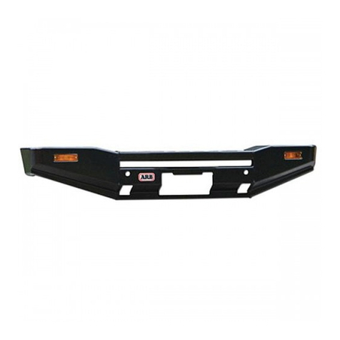
ARB WINCH BULL BAR TO SUIT
SUZUKI SIERRA WITH 5 OR 6,000lb WINCH No 3424010/110
WARNING
THIS BULL BAR MUST NOT BE FITTED TO AIRBAG EQUIPPED VEHICLES.
FITMENT TO AIRBAG EQUIPPED VEHICLES MAY INTERFERE WITH THE
PROPER OPERATION OF THE AIRBAGS AND MAY RESULT IN SERIOUS INJURY.
TAKE NOTE OF THE FOLLOWING:
•THIS PRODUCT MUST BE INSTALLED EXACTLY AS PER THESE INSTRUCTIONS USING ONLY THE
HARDWARE SUPPLIED.
•IN THE EVENT OF DAMAGE TO ANY BULL BAR COMPONENT, CONTACT YOUR NEAREST
AUTHORISED ARB STOCKIST. REPAIRS OR MODIFICATIONS TO THE IMPACT ABSORPTION SYSTEM
MUST NOT BE ATTEMPED.
•DO NOT USE THIS PRODUCT FOR ANY VEHICLE MAKE OR MODEL, OTHER THAN THOSE SPECIFIED
BY ARB.
•DO NOT REMOVE LABELS FROM THIS BULL BAR.
•THIS PRODUCT OR IT’S FIXING MUST NOT BE MODIFIED IN ANY WAY.
BULL BAR FITTING KIT No 6171072 OPTIONALWINCH MOUNT KIT No 3524010
PART No QTY DESCRIPTION
6151251 2 BOLT M16 X 2.0 X 150
4581051 4 5/8” FLAT WASHER
6151252 2 NYLOC NUT M16 X 2.0
4581048 6 BOLT UNC 3/8” X 1 ¾”
180302 4 CABLE TIE
BLB1100 2 BATTERY LEAD
BLR1100 1 BATTERY LEAD
3757857 1 BRACKET RFL BOLT ON
PART No QTY DESCRIPTION
6151077 4 3/8 X 2 ¾” BOLT
6151071 2 3/8 X 1” BOLT
6151123 6 3/8” NUT
4581040 12 3/8” FLAT WASHER
4581048 6 M10 SPRING WASHER
4581072 3 ¼” FLAT WASHER
5811005 2 CHASSIS SLEEVE LONG (43mm)
5811006 2 CHASSIS SLEEVE SHORT (38mm)
3751485 1 NUMBER PLATE BRACKET
6151180 4 M6x20mm BOLTS
6151128 4 M6 FLANGE NUTS
6151046 4 M6 FLAT WASHERS
1212174 4 SPEED NUTS
PT003-12B 4 RUBBER CAP FOR SCREWS
2/10/2007 Page 2 of 3 3782574
TOOLS REQUIRED
Basic tool kit and drill with 1/2” drill bit.
FITTING THE 5 & 6,000lb WINCH
1. Place the bull bar on a suitable stand.
2. Remove the roller fairlead side rollers by removing the circlips from each pin. These pins will be replaced with
5/8” x 6” UNC bolts and 5/8” UNC nyloc nuts. Discard side pins and circlips.
3. New mounting holes must be drilled into the roller fairlead to line up with the winch mounting holes in the bull
bar. Drill two 1/2” diameter holes at the position shown in the diagram. Mark out new holes 34mm down from
the original hole centres and drill out to 1/2” holes. (Refer to the diagram.)
4. To fit the winch into bull bar, the winch gearbox must first be rotated to ensure control handle is in the correct
location. Loosen and remove all the cap head bolts. CAUTION: Do not remove the gearbox. Pull the gearbox
just out enough to rotate the handle anti-clockwise by 72° to the new position. (Refer to the diagram.)
NOTE: When fitted, the winch clutch handle should protrude through the “D” cut-out in the top of the bull bar. he
gearbox is situated on the left hand side of the bull bar (as viewed from inside the vehicle). The cable spools
from the bottom.
5. Position the winch on top of a 20 or 60 litre drum with mounting holes facing upwards.
6. Place the bull bar on top of the winch and align the mounting holes. Using bolts supplied from the winch kit,
finger tighten the two upper bolts.
7. Place the roller fairlead over the lower holes on the bull bar and secure in place using the 3/8” x 1 1/2” bolts
and flat washers (from the Warn winch bolt kit). Ensure winch is correctly aligned and tighten all bolts.
8. Fit the two 5/8” x 6” bolts and flat washers through bull bar, roller fairlead and side rollers. Fit the 5/8” nyloc
nuts and tighten making sure the rollers turn freely. Tighten all the bolts.
9. Mount the winch into the rear of the bull bar. Visually locate the top holes and secure the winch using the 3/8”
x 1 1/4” bolts (from the Warn winch bolt kit) and four M10 (3/8”) flat washers from the ARB fitting kit.
2/10/2007 Page 3 of 3 3782574
FITTING THE BULL BAR TO THE VEHICLE
10. Remove indicator assemblies from the existing bumper bar.
11. Remove the number plate and bumper from vehicle. Place aside the number plate and fasteners.
12. Fit the four sleeve inserts into the chassis rails. NOTE: The longer sleeves (43mm) fit above the shorter
(38mm) sleeves.
13. Lift the bull bar into position and fit the four 3/8” x 2¾” bolts, nuts and washers into the uprights and through
the chassis rails. Finger tighten the nuts.
14. Using the original bumper mounting bolts, fit the outer bull bar brackets onto the original bumper mounts.
15. Position the bull bar in the final position and tighten the chassis rail bolts. Remove the outer bracket bolts and
drill out to 3/8” diameter. Fit the two 3/8” x 1” bolts, nuts and washers.
16. Refit the indicator assemblies to the bull bar. Use the original screws from the indicators in the vehicle
bumper, plus the four flat speed nuts. Fit the four rubber caps for the screws over the exposed parts of the
screws behind the speed nuts to prevent injuries from the sharp screws. Refit the number plate with the bracket
(No 3751485) supplied and the M6 bolts, flat washers and flange nuts.
17. Connect the winch control box cables to the winch motor. Refer to the Warn handbook for additional
information. Remove the short (+) & (-) winch cables and replace with the long cables supplied. Refer to the
Warn winch manual for vehicle wiring instructions.
18. The winch control box must be mounted under the bonnet in a convenient location, using the two 1/4” nuts, flat
washers and spring washers (supplied in Warn kit).
IMPORTANT: Ensure that these cables are installed well clear of sharp, hot or moving objects. Secure the
winch cables to the vehicle with the supplied cable ties.
WARNING: UNDER NO CIRCUMSTANCES IS THE WINCH TO BE USED BEFORE THE OWNER’S
MANUAL HAS BEEN READ AND UNDERSTOOD. FAILURE TO COMPREHEND THE MANUAL
CONTENTS COULD RESULT IN OPERATOR DANGER AND WINCH FAILURE.

This manual suits for next models

1

Other ARB Automobile Accessories manuals

ARB RD101 User manual

ARB

ARB RD101 User manual

ARB AC08C User manual

ARB

ARB AC08C User manual

ARB 341 4460 User manual

ARB

ARB 341 4460 User manual

ARB AIRLOCKER RD142 User manual

ARB

ARB AIRLOCKER RD142 User manual

ARB SA290AA290 User manual

ARB

ARB SA290AA290 User manual

ARB 3917140 User manual

ARB

ARB 3917140 User manual

ARB AIRLOCKER RD156 User manual

ARB

ARB AIRLOCKER RD156 User manual

ARB Airlocker RD210 User manual

ARB

ARB Airlocker RD210 User manual

ARB AIRLOCKER RD231 User manual

ARB

ARB AIRLOCKER RD231 User manual

ARB 3500720 User manual

ARB

ARB 3500720 User manual

ARB 3414470 User manual

ARB

ARB 3414470 User manual

ARB 3450080 User manual

ARB

ARB 3450080 User manual

ARB RD151 User manual

ARB

ARB RD151 User manual

ARB Airlocker RD161 User manual

ARB

ARB Airlocker RD161 User manual

ARB AIRLOCKER RD109 User manual

ARB

ARB AIRLOCKER RD109 User manual

ARB INTENSITY IQ User manual

ARB

ARB INTENSITY IQ User manual

ARB Airlocker RD259 User manual

ARB

ARB Airlocker RD259 User manual

ARB 3417100 User manual

ARB

ARB 3417100 User manual

ARB Airlocker RD232 User manual

ARB

ARB Airlocker RD232 User manual

ARB 3434040 User manual

ARB

ARB 3434040 User manual

ARB RD121 Operating and maintenance instructions

ARB

ARB RD121 Operating and maintenance instructions

ARB 10900013 User manual

ARB

ARB 10900013 User manual

ARB 819105 User manual

ARB

ARB 819105 User manual

ARB Airlocker RD152 User manual

ARB

ARB Airlocker RD152 User manual

Popular Automobile Accessories manuals by other brands

Hayman Reese 41319R installation instructions

Hayman Reese

Hayman Reese 41319R installation instructions

Seat 5F0.054.752.B Fitting instructions

Seat

Seat 5F0.054.752.B Fitting instructions

Feniex Geo G-1018 instruction manual

Feniex

Feniex Geo G-1018 instruction manual

Arkon CM012 installation instructions

Arkon

Arkon CM012 installation instructions

Whispbar K319W Fitting instructions

Whispbar

Whispbar K319W Fitting instructions

Thule Rapid System 1762 instructions

Thule

Thule Rapid System 1762 instructions

B&M 80212 installation instructions

B&M

B&M 80212 installation instructions

Jaeger 16500592 Fitting instructions

Jaeger

Jaeger 16500592 Fitting instructions

Front Runner RRAC189 Assembly and mounting instructions

Front Runner

Front Runner RRAC189 Assembly and mounting instructions

CargoBrite CB-KITSTD2 installation guide

CargoBrite

CargoBrite CB-KITSTD2 installation guide

Thule Upright Bike Carrier 525 installation instructions

Thule

Thule Upright Bike Carrier 525 installation instructions

ULTIMATE SPEED 292911 Assembly and Safety Advice

ULTIMATE SPEED

ULTIMATE SPEED 292911 Assembly and Safety Advice

Brodit ProClip 854208 manual

Brodit

Brodit ProClip 854208 manual

Axxess AXGMLN-08 installation instructions

Axxess

Axxess AXGMLN-08 installation instructions

Kuat NV user guide

Kuat

Kuat NV user guide

Reverie R01SB0465 Fittings guide

Reverie

Reverie R01SB0465 Fittings guide

NORDRIVE BIKE-ONE Fitting instructions

NORDRIVE

NORDRIVE BIKE-ONE Fitting instructions

RUD CENTRAX Fitting instructions

RUD

RUD CENTRAX Fitting instructions

manuals.online logo
manuals.online logoBrands
  • About & Mission
  • Contact us
  • Privacy Policy
  • Terms and Conditions

Copyright 2025 Manuals.Online. All Rights Reserved.