Flo SmartTWO-BSR User manual

ilheenTable of Contents
TM
SmartTWO -
BSR
Installation Guide
TM

Table of Contents
1. Maintenance and Safety ............................................................................................................................................... 4
2. General .............................................................................................................................................................................. 5
2.1. Configurations ....................................................................................................................................................... 5
2.2. Specifications ........................................................................................................................................................ 6
2.3. Dimensions .............................................................................................................................................................. 7
3. Site Layout ....................................................................................................................................................................... 8
3.1. Pedestal Positioning ............................................................................................................................................. 8
3.2. Concrete Base ....................................................................................................................................................... 9
3.2.1. Concrete Base – For Master Pedestals with an Integrated Electrical Distribution Panel ................... 9
3.2.2. Concrete Base – For Pedestals without an Integrated Electrical Distribution Panel ........................... 11
4. Electrical Configuration ................................................................................................................................................ 13
4.1. Power Input: Deported Electrical Distribution Panel ..................................................................................... 13
4.1.1. 240V Split Phase Configuration .................................................................................................................... 14
4.1.2. 208 V 3-Phase Supplied by a Deported Electrical Distribution Panel ..................................................... 15
4.2. Power Input: Integrated Electrical Distribution Panel ................................................................................... 16
4.2.1. 240 V Split Phase Configuration .................................................................................................................... 17
5. Integrated Electrical Distribution Panel ..................................................................................................................... 18
5.1. Electrical Design ................................................................................................................................................... 18
5.2. Mechanical Design ............................................................................................................................................... 18
5.2.1. Anchor Points .................................................................................................................................................... 19
5.3. Installation ............................................................................................................................................................ 20
6. Electrical Installation .................................................................................................................................................... 22
6.1. Lifting the Pedestal ............................................................................................................................................. 22
6.2. Pedestal Installation ........................................................................................................................................... 23
6.3. Integrated Electrical Distribution Panel Installation (Optional) ................................................................. 23
6.4. Power Supply Cable Installation ....................................................................................................................... 24
6.4.1. Deported Electrical Distribution Panel ........................................................................................................ 25
6.4.2. Integrated Electrical Distribution Panel ...................................................................................................... 25
6.5. Charging Station Connection ............................................................................................................................27
6.5.1. Pedestal Panel Removal ................................................................................................................................. 28

6.5.2. Charging Station Cable Routing and Ground Connection ...................................................................... 29
6.5.3. Charging Station Wire Connection .............................................................................................................. 32
7. Charging Station Installation ...................................................................................................................................... 33
7.1. Pedestal Access Door Installation ................................................................................................................... 33
7.2. Pedestal Panel Installation ................................................................................................................................ 33
7.3. Charging Station and Connector Installation ................................................................................................ 35
7.4. Preliminary Tests and Commissioning ............................................................................................................ 36
7.5. Preliminary Tests and Commissioning ............................................................................................................. 37
8. Copyright and Liability ................................................................................................................................................. 38

1. Maintenance and Safety
IMPORTANT SAFETY INSTRUCTIONS - PLEASE DO NOT DISCARD THESE INSTRUCTIONS
Read this guide carefully before installing the Electric Vehicle Supply Equipement (EVSE)
1. This dual charging station curbside pedestal was designed to be ground-based,
installed on a non-combustible surface, and to host two SmartTWOTM charging
stations.
2. Verify with local authorities that the location where the EVSE is to be installed is free
from underground pipelines or electrical equipment, otherwise you might inflict
serious injuries on yourself or bystanders.
3. Connect the power input of the charging station bases with 2 AWG to 8 AWG caliber
copper or aluminum conductors rated for usage at a temperature of at least 75 °C
(176 °F.)
4. Grounding: To ensure the safe operation of FLO® EVSEs, they must be connected to
a grounding circuit compliant with local regulations and installed by a certified
electrician.
5. Communicate with a certified contractor, certified electrician, or trained installer to
ensure compliance with the local building code, regulations, security standards and
weather conditions.
6. Any EVSE part alteration will automatically void the warranty.
7. Handle parts with care since they can be sharp-edged. Always use safety glasses
and gloves when unpacking and installing the EVSE.
8. Some parts are heavy and could cause manual handling injuries. Always use proper
lifting techniques and wear safety boots during installation.
9. Never insert your finger into the electric vehicle connector.
10. Never use the EVSE if the power cable seems damaged or if the insulation is
damaged.
11. Never use the EVSE if the main case is broken, cracked, open or damaged.
12. This EVSE was designed to be used with electric vehicles equipped with an SAE-
J1772 connector.
13. This EVSE is to be used to charge vehicles that do not require a ventilated
environment during charging.
14. Replacement of the EVSE charging station, or cable connector must be performed by
qualified service personnel.
15. If the enclosure of the EVSE’s charging station is opened, all gaskets must be
replaced.
16. Do not install the charging station on or over a combustible surface.
2. General
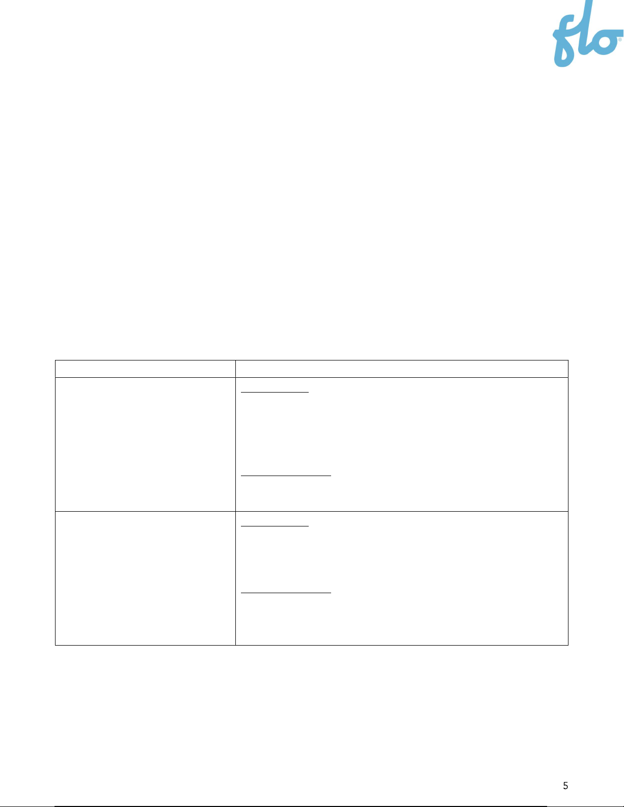
2.1. Configurations
The SmartTWO-BSRTM can be purchased with different configurations. The type of
configuration needed varies based on the site layout.
Model
Description
Master SmartTWO-BSR Power input
From an integrated distribution cabinet (Installed at the
back of the pedestal – Not provided by FLO) OR from a
deported distribution cabinet.
Communication
Integrated cellular gateway
Auxiliary SmartTWO-BSR Power Input
From the Master SmartTWO-BSR integrated distribution
panel OR a deported distribution panel.
Communication
No gateway. Communicates via zigbee communication
protocol with the Master SmartTWO-BSR gateway.
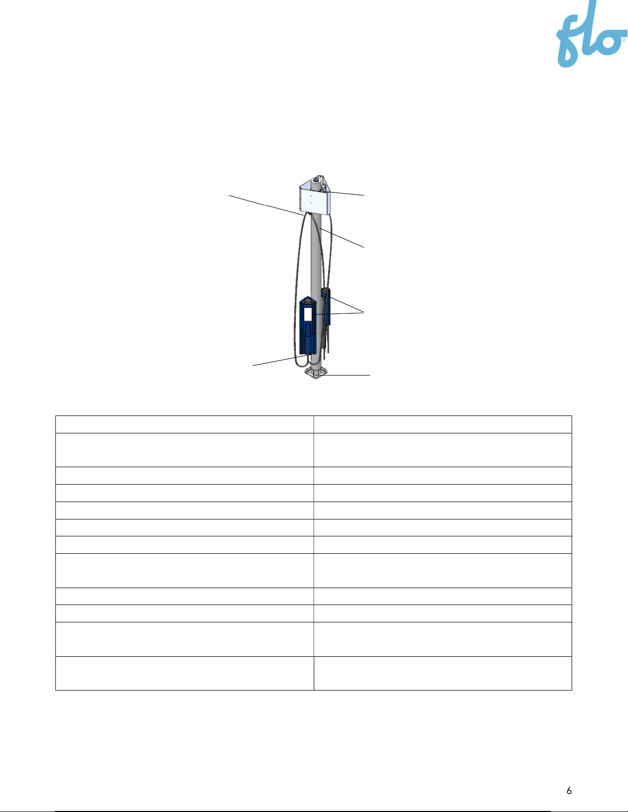
2.2. Specifications
The SmartTWO-BSR is made of one dual pedestal, two SmartTWO charging stations and
two cable management systems. Depending on the chosen configuration, the SmartTWO-
BSR can also be provided with a Cellular Gateway.
Product family
SmartTWO-BSR
Models Master SmartTWO-BSR
Auxiliary SmartTWO-BSR
Aluminum casing Type 3R
Storage temperature -40 °C to 70 °C / -40 °F to 158 °F
Humidity Up to 95% (non-condensing)
Weight
80 kg / 175 lb
s
Electrical load
2 x 30 A @ 240 VAC or 208 VAC
Output current 6 A to 30 A (Maximum configurable by
software for each charging station)
Frequency
60 Hz
Accessibility ADA Compliant
Certifications CSA certified
USA: UL2594, UL2231-1, UL2231-2, CTEP
EMI Compliance
CAN
-
ICES
-
003 (A) / NMB
-
3 (A) USA
-
FCC
47 CFR part 15 class A
Dual pedestal
SmartTWO charging stations
Cellular Gateway (Master
configuration only)
Cable management system
Pedestal door opening Pedestal mounting bolts
openings

2.3. Dimensions
The dimensions below apply to both Master and Auxiliary configurations of the SmartTWO-
BSR.
3. Site Layout
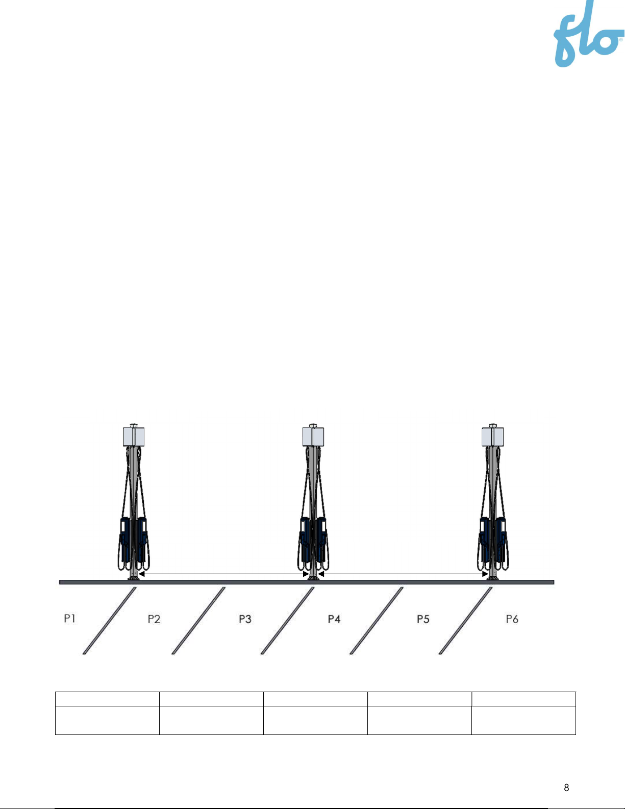
3.1. Pedestal Positioning
For each installation site, one master curbside pedestal should be installed, followed by
auxiliary curbside pedestals (optional). The master curbside pedestal is equipped with a
cellular LTE communication gateway that will link with up to 18 auxiliary unit charging
stations (up to 9 pedestals) in close vicinity to the centralized network management
server.
Prior to starting the installation, make sure that the specific location chosen for the master
curbside pedestal installation has a good LTE signal strength. See the reference table
below for typical LTE signal strengths. To ensure linking every charging station on a site,
the maximum distance between any unit is 160’ (48.7 meters), without any obstacle
interfering with the line of sight.
RECOMMENDATION: Each pedestal is equipped with two charging stations. We
recommend installing them at the junction of 2 successive parking spaces on the side of a
street.
LTE signal strength
Excellent Good Fair Poor Deadzone
-90 dBm -91 dBm to -105
dBm
-106 dBm to -110
dBm
-111 dBm to -119
dBm
-120 dBm
Master pedestal
Auxiliary pedestal
Auxiliary pedestal
Maximum distance 160’ (48.7 m) Maximum distance 160’ (48.7 m)

3.2. Concrete Base
The installer should make a concrete base on site (or use a prefabricated base). Two
configurations are suggested depending on whether there is an integrated or deported
electrical distribution panel.
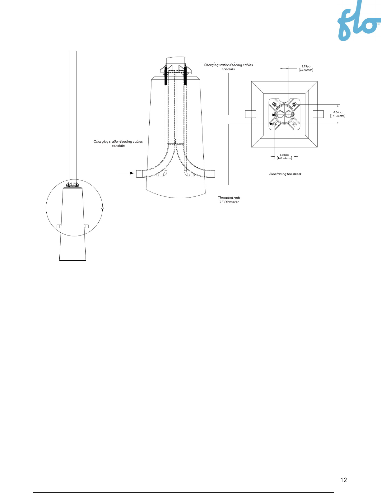
3.2.1. Concrete Base – For Master Pedestals with an
Integrated Electrical Distribution Panel
When an electrical panel is installed on the back of the SmartTWO-BSR pedestal, it requires
a separate conduit for the power input coming from the grid and going to the panel. The
pedestal has a provision at the center of its base to let the power input pass from the
concrete base up to the electrical panel.
The concrete base should have the following characteristics:
Four 1” (25.4 mm) diameter threaded rods, spaced according to the pattern
shown below.
The rods should extend 4” (101.6 mm) out of the concrete base.
Two cable conduits to pass the charging station wiring feeding the auxiliary
SmartTWO-BSR.
The cable conduits should exceed the concrete base by 2” (50.8 mm) in the
center of the mast.
One 2" to 3" (50.8 to 76.2 mm) diameter aluminium cable conduit to pass the grid
cables to the integrated electrical distribution panel dedicated opening.

NOTE: The power input position for the integrated electrical distribution cabinet might
vary. Validate that the cable can be routed correctly from the pedestal opening
dedicated to the grid cabling conduit, to the position of the power input in the electrical
distribution panel.

3.2.2. Concrete Base – For Pedestals without an Integrated
Electrical Distribution Panel
This configuration is suitable for Auxiliary pedestals, and for Master pedestals without an
integrated distribution panel. These configurations do not require grid power cables to be
connected; therefore, the concrete base does not need a separate conduit to pass the grid
cables.
The concrete base should have the following characteristics:
Four 1” (25.4 mm) diameter threaded rods, spaced according to the pattern
shown below.
The rods should extend 4” (101.6 mm) out of the concrete base.
Two cable conduits to pass the wiring feeding the charging stations.
The cable conduits should extend over the concrete base by 2” (50.8 mm) in the
center of the mast.
4. Electrical Configuration
Different electrical configurations are possible depending on the incoming power input.
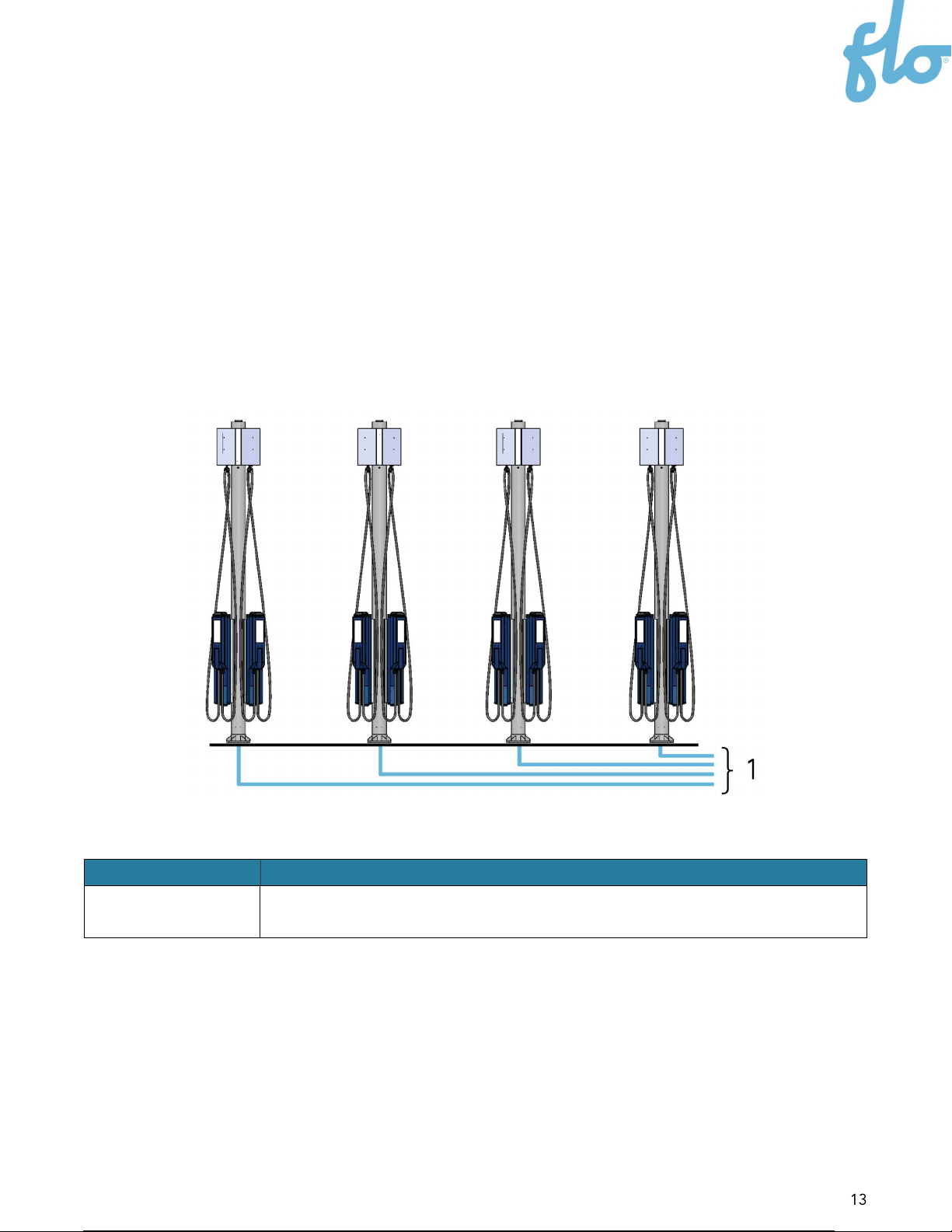
4.1. Power Input: Deported Electrical Distribution Panel
These two configurations imply that the electricity is supplied by a deported electrical
distribution panel that is not mounted on a Master SmartTWO-BSR pedestal. One conduit
per pedestal is required to bring the cables to their respective pedestals.
Number
in Image
Description
1
Only 1 conduit per pedes
tal to bring the 2x 40 A circuit from the
deported distribution panel.
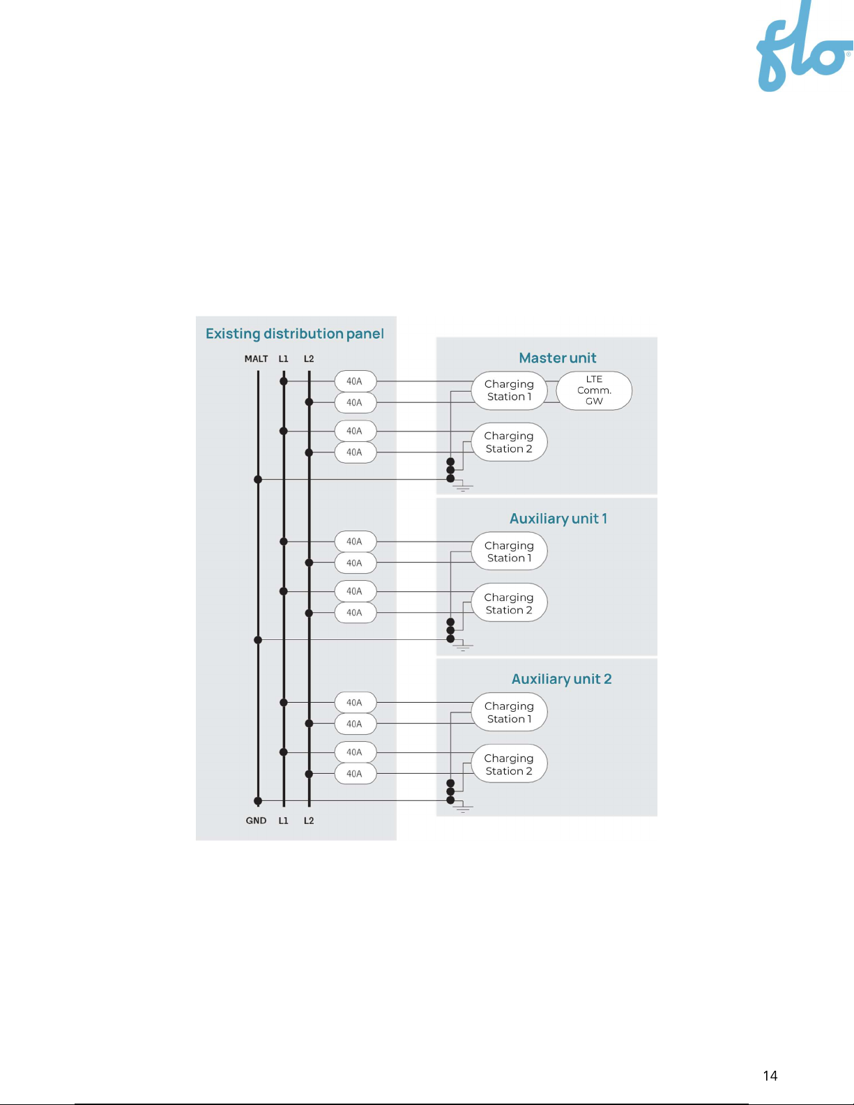
4.1.1. 240V Split Phase Configuration
To feed each pedestal, two 240 V 40 A circuits (without neutral) are required to power the
208/240 V 30 A charging stations. In this case, only one conduit bringing all the cables in
the center of the mast is required to feed the two charging stations installed on the
pedestal.
Split-Phase Supply from an Electrical Cabinet
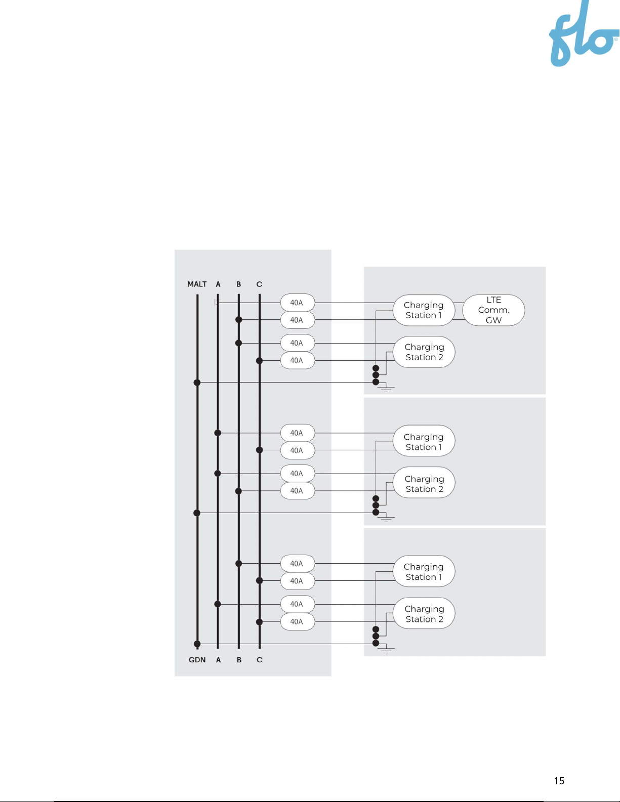
4.1.2. 208 V 3-Phase Supplied by a Deported Electrical
Distribution Panel
To feed each pedestal, two x 40 A phase to phase circuits (without neutral) are required to
power the 208/240 V 30 A charging stations. We highly recommend evenly distributing the
connections among the 3 phases in order to keep the load as balanced as possible. In this
case, only one conduit bringing all the cabling inside the center of the mast is required to
feed the two charging stations installed on the pedestal.
Three Phase Supply from an Electric Distribution Panel
Exis
ting
D
istribution
P
anel
Master Unit
Auxiliary Unit 1
Auxiliary Unit 2
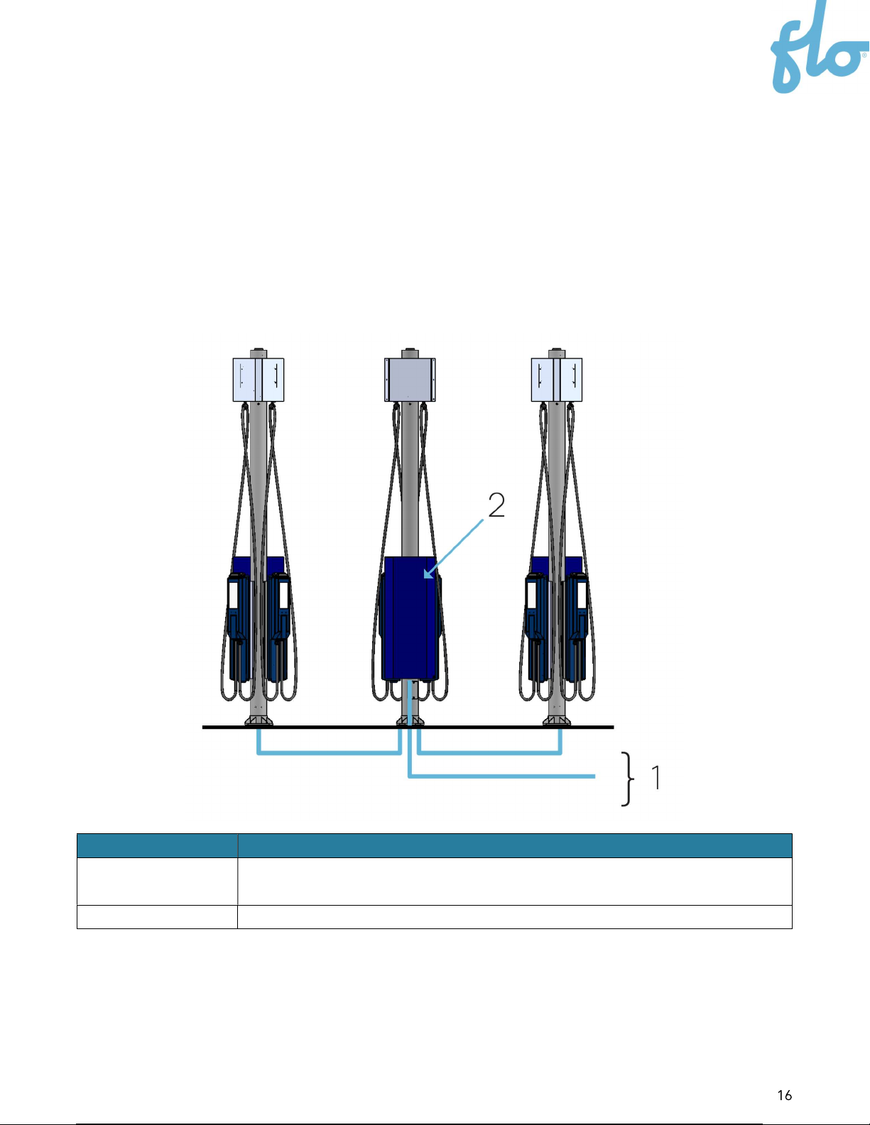
4.2. Power Input: Integrated Electrical Distribution
Panel
This configuration implies that an electrical distribution panel is installed on the back of the
Master pedestal. The recommended layout should have one Master pedestal and up to two
Auxiliary pedestals connected to the electrical distribution panel. See the
Integrated
Electrical Distribution Panel
section for more information.
Number Description
1
2 to 3 inch
(50.8 mm to 76.2 mm) conduit bringing the feedi
ng cables
from the grid directly into the integrated electrical distribution panel
2 Integrated electrical distribution panel (Not provided by FLO)
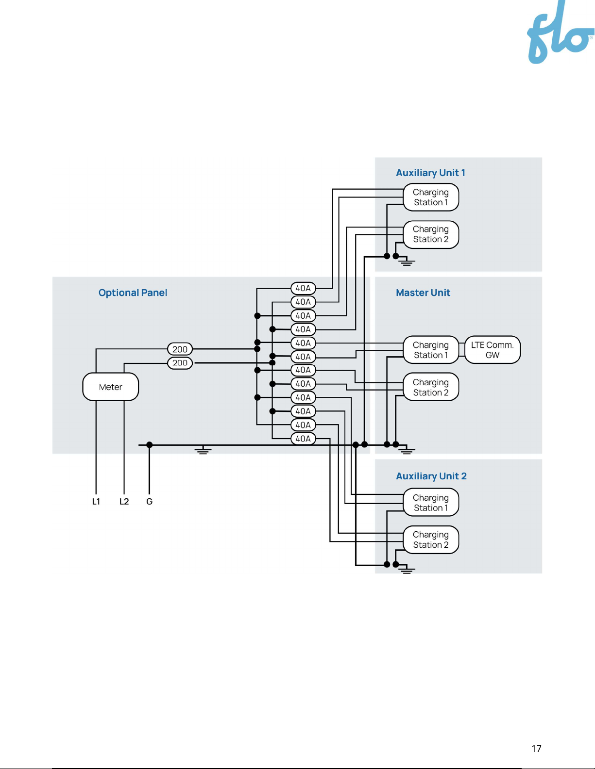
4.2.1. 240 V Split Phase Configuration
To feed each pedestal, two 240 V 40 A circuits (without neutral) are required to power the
208/240 V 30 A charging stations. In this case, a separate conduit is needed to bring the
grid cable to the integrated electrical distribution panel.

5. Integrated Electrical
Distribution Panel
It is possible to install an electrical distribution panel that follows local regulations on the
back of the Master SmartTWO-BSR pedestal.
NOTE: FLO only provides physical dimensions and guidelines. It does not provide electrical
distribution panels and does not participate in the design of custom electrical distribution
panels.
5.1. Electrical Design
The electrical design of the integrated electrical distribution panel should consider the
pedestal and charging station’s layout. The Master SmartTWO-BSR pedestal is designed
with internal space to allow cable routing to up to six charging stations (two for the Master
pedestal, four for auxiliary pedestals).
5.2. Mechanical Design
The Master SmartTWO-BSR pedestal is designed with provisions to install an electrical
distribution panel (Not provided by FLO) on its back. The latter can be installed directly at
the back of the Master SmartTWO-BSR pedestal using the dedicated threaded anchor
points, or on a fabricated rack designed to fit on the Master SmartTWO-BSR pedestal.
The section below provides guidelines to design a custom rack that will fit on the
SmartTWO-BSR pedestal.
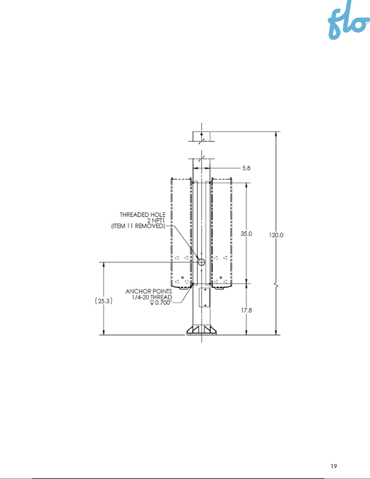
5.2.1. Anchor Points
The fabricated rack should have the following anchor point characteristic:
Four anchor points with ¼-20 threaded inserts
RECOMMENDATION: We recommend designing horizontal slotted holes to match the
anchor positioning tolerances (5.8"± 1/8" or 147.32 mm ± 3.175 mm).

RECOMMENDATION: Use 3/4" (19.05 mm) spacers between the anchor points and the
electrical distribution panel. This will prevent interference between the back of the
pedestal and the electrical distribution panel.
5.3. Installation
The electrical distribution panel should be installed securely on the pedestal using the
fabricated rack. The opening for the conduits should be sealed properly.
The next steps describe how to install the electrical distribution panel on the back of the
Master SmartTWO-BSR pedestal:
1. Remove the pedestal upper access door by unscrewing the two screws. A 2NPT1
hole will be exposed.
Access
door
2NPT1
hole
Table of contents
Other Flo Batteries Charger manuals


Popular Batteries Charger manuals by other brands


GYS
GYS CT 160 instruction manual

Everpower Electronics
Everpower Electronics EPA 1204 instruction manual

Kemo Electronic
Kemo Electronic M172N quick start guide

VISIONARY DESIGNS
VISIONARY DESIGNS InCharg MOD-1456 Setup instructions

Transmedia
Transmedia MW 1 L user manual

Jegs
Jegs 81961 installation instructions


