Flo Home G5 User manual

Installation guide
FLO Home
G5 Model

Languages
English 3
Français 19
A customer experience
or technical support
representative can assist
you!
Customer and Technical Support
For any questions regarding charging
station installation, conguration or any
technical problem.
1-855-543-8356
You can also contact us at:
service@o.com
Un représentant du
service à la clientèle ou
un agent du soutien
technique peut vous
aider !
Service à la clientèle et Soutien
technique
Pour toutes questions relatives à
l’installation et à la conguration des
bornes de recharge, ou tout autres
problèmes techniques.
1-855-543-8356
Vous pouvez également nous contacter:
service@o.com
Assistance

3
FLO Home G5 | Installation guide | o.com | October 2018
Table of Contents
Assistance 2
Safety Instructions 4
Before You Install 5
Box Contents 6
Installing the Station 7
Setting the Current Limit 9
Light Indicator 11
Charging Station Serial Number 13
Warranty - USA 14
Warranty - CA 16
Casing: 100% aluminum NEMA 4X Certied, designed for outdoor or indoor installation
Finish: Anthracite grey with high resistance coating
Voltage: 208 - 240 V @ 60 Hz
Output Current: 30 A
Maximum Output Power: 7.2 kW @ 240 V or 6.2 kW @ 208 V
Cable: 7.62 m (25 ft) ultra-exible cable
Charging Connector: SAE J1772 designed to withstand over 10,000 charging cycles
Security Features: Integrated GFCI circuit breaker (20 mA, 3 reset attempts at 15-minute
intervals)
Operating Temperature: -40 °C to 50 °C (-40 °F to 122 °F)
Weight with cable, connector and mounting plate: 11.23 kg (24.76 lbs)
Communication Interface: None

4October 2018 | o.com | Installation guide | FLO Home G5
Safety Instructions
INSTRUCTIONS PERTAINING TO A RISK OF FIRE OR ELECTRIC SHOCK
SAVE THESE INSTRUCTIONS!
WARNING: When using electrical appliances, basic precautions should always be followed.
This manual contains important instructions that must be followed when installing,
operating and maintaining the unit. Please read this guide carefully before attempting to
install the charging station.
1. CAUTION -To reduce the risk of re, connect only to a branch circuit provided with a
maximum surge protection of 40 A in accordance with the Canadian Electrical Code
(CSA C22.1-12) and the National Electrical Code (ANSI / NFPA 70).
2. This charging station has been designed for wall or post mounting.
3. Ensure that the mounting surface for the wall or pole is strong enough to support the
weight of the charging station and that the anchors used are compatible with the
surface.
4. Verify that there is no piping, electrical installation or underground electrical installation
in the area where you will install the station, to avoid serious injuries.
5. Connect the power supply of the charging station with caliber 6 AWG to 8 AWG copper
conductors rated for usage at a temperature of at least 75 °C.
6. This product must be connected to a grounded, metal, permanent wiring system, or an
equipment-grounding conductor must be run with the circuit conductors and
connected to the equipment grounding terminal and installed by a certied electrician.
7. Communicate with a certied contractor, certied electrician or trained installer to
ensure compliance with local building code, regulation, security standards and weather
conditions.
8. Any modication to any part of the charging station will void the warranty.
9. Handle parts with care, since they can be sharp-edged. Always use safety glasses and
gloves when unpacking and installing.
10. Do not install on or over a combustible surface.
11. The power supply cables of the charging station must be rated FT2 minimum.
12. The input cable strain relief, conduits or armed-cable bushings and adapter:
A) have to be certied for both Canada and USA;
B) have to be waterproof (NEMA 4X);
C) have to be suitable for the outside diameter of the chosen cable and suitable for
mounting into a 28.17 mm (1.109 in) diameter opening (for connection through the
bottom or back cable opening).
General safety instructions
This device should be supervised when used around children.
Never insert your nger into the electric vehicle connection.
Never use the charging station if the exible power cord or EV cable is frayed, has broken
insulation, or any other signs of damage.
Never use the charging station if the enclosure or the EV connector is broken, cracked,
open, or shows any other signs of damage.
This charging station was designed to be used with electric vehicles equipped with
a SAE J1772 connector.
This charging station is to be used to charge vehicles that do not require a ventilated
environment during charging.
Always disconnect the power supply of the charging station before servicing.

5
FLO Home G5 | Installation guide | o.com | October 2018
Before You Install
IMPORTANT CONSIDERATIONS WHEN INSTALLING THE STATION
The station must be installed by a certied electrician.
The station has built-in protection against overvoltage conditions and leakage current to
ground.
Any alteration to any part of the charging station will void the warranty.
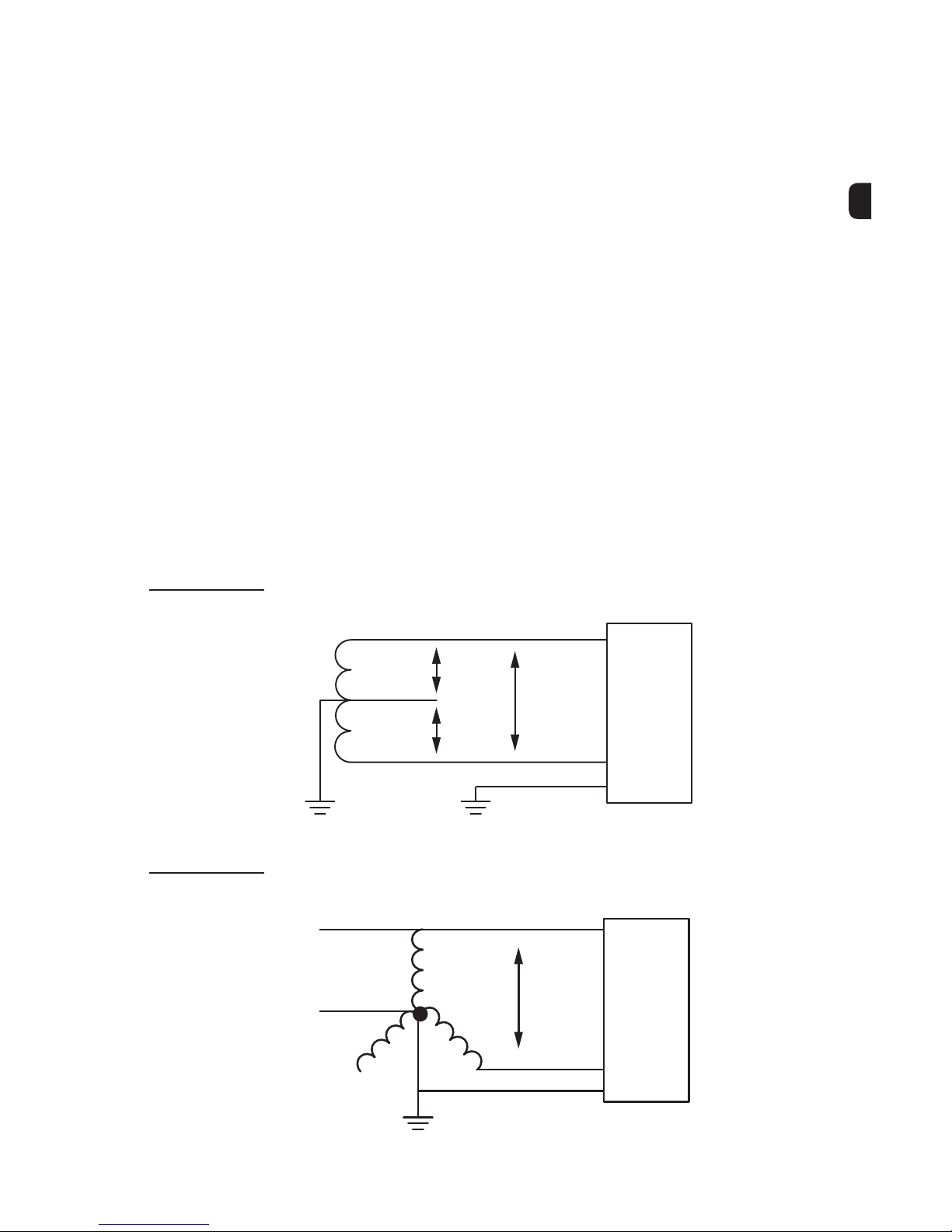
Connecting your new charging station requires:
- Single-Phase 120/240 VAC supply (gure 1) or 3-Phase 120/208 VAC supply (gure 2)
- A connection with 6 AWG to 8 AWG copper conductors
- Protection by a 40 A double circuit breaker or two fuses
- 2 phases and a ground connection with 120 VAC between each phase and ground
NOTE: neutral is not required.
Maximum output power: 7.2 kW @ 240 V or 6.2 kW @ 208 V
Figure 1
Single-Phase 120/240 VAC
GND
120
VAC 240
VAC
Charging
Station
120
VAC
L1
L2
Ground
Ground
3-Phase 120/208 VAC
Figure 2
GND 208
VAC Charging
Station
AL1
L2
BC
Ground

6October 2018 | o.com | Installation guide | FLO Home G5
Box Contents
1 Charging station
2 Cable and charging connector
3 Wall mounting plate
4 NEMA 6-50 POWER CORD PLUG (for US Models Only)
Recommended height to facilitate handling of the connector, as well as preventing the cable
from touching the ground.
Floor
60 in
152.4 cm
17 in
43.2 cm
7.6 in
19.3 cm 6.9 in
17.5 cm

7
FLO Home G5 | Installation guide | o.com | October 2018
Installing the Station
NOTE
The power supply cable can be inserted from
the rear (a) or from under (b) the station:
- 3/4˝ knockout (a) and (b)
- Remove a single cap
- Strain relief not included
1 Disassemble the front casing by removing the 2 front screws and then separate the
mounting plate by unscrewing the lower screw.
WARNING: Your charging station must be installed by a licensed electrician.
Front casing Back housing Mounting plate
Front screws Lower screw
b
a
2 Use the mounting plate as a drilling template after determining the input to be used,
either at the rear or under the station.

8October 2018 | o.com | Installation guide | FLO Home G5
3 Hang the mounting plate securely
to a stable surface using a
minimum of 3 anchor screws.
4 Insert the conductors and secure the strain relief to the rear housing so that the
conductors are long enough to reach the terminals.
5 Secure the rear housing of the station to the mounting plate.
6 Screw the lower screw to secure the mounting.
7 Connect the two power wires (L1 and L2) and the ground wire (GND).
Anchoring screws
Mininum of 3
Maximum of 6
Wall structure
51 mm
2.25"
27 mm
1.06"
42 mm
1.69"
152 mm
6.00"
152 mm
6.00"
178 mm / 7.62"
107 mm
4.22"
406 mm
16.96"
L1
L2
GND
Nominal torque for conductors
L1-L2: 6 AWG = 16 lbs-in
8 AWG = 16 lbs-in
GND: 6 AWG = 45 lbs-in
8 AWG = 40 lbs-in
WARNING:
ALWAYS use a manual screwdriver; DO
NOT use an Impact Driver, risk voiding the
warranty if screws are damaged.
8 Tighten the connector nut. Ensure the wire is secure.

9
FLO Home G5 | Installation guide | o.com | October 2018
9 Install the front housing of the charging station:
A) Hang the top by presenting the front housing at an angle of about 30 degrees, then
pivot vertically without forcing.
B) Tighten the 2 front screws with a nominal torque of 55 lbs-in.
Detail A
About
30°
A
B
10 Switch on the electrical circuit breaker.
Wiring the NEMA 6-50
Power Cord Plug
1 Remove the rubber cap (located at the bottom
of the charging station).
2 Pull cables inside the station. Ensure the plug blades
are facing the wall.
3 Follow steps, ‘‘Installing the Station’’ 7 to 9 (p8 and p9).
4 Connect to power outlet
5 Switch on the electrical circuit breaker.

10 October 2018 | o.com | Installation guide | FLO Home G5
Setting the Current Limit
By default, the FLO Home G5 is set to maximum power (factory). If your home’s electrical
infrastructure does not allow the charging station at maximum power (or preventing any
potential current overload), it can be reduced using the Current Limiter Switch.
WARNING: Your charging station must be installed by a licensed electrician.
Procedure
1 Switch “OFF” the charging station:
A) In the Breaker Panel set the circuit breaker switching the charging station to “OFF”.
B) Conrm the charging station’s Light Indicator is “OFF”.
NOTE: Before handling the charging station, use a multimeter to determine
if an electrical cable is hot. Keep in mind, it is possible for more than
one wire to be live.
2 Remove charging station front housing (See p. 9).
3Locate Current Limiters switch.
Switch

11
FLO Home G5 | Installation guide | o.com | October 2018
4 Using a at-bladed screwdriver, gently rotate the Switch to the desired position.
(See table below).
Current Limiters Switch
Position
G5 charging station
Power (A)
Circuit Breaker (A)
* in Breaker Panel
030 40
127 35
224 30
320 25
416 20
512 15
6810
7610
8Not Used Not Used
9Not Used Not Used
5 Put back the front housing.
6 Switch “ON” the charging station.

12 October 2018 | o.com | Installation guide | FLO Home G5
Blue
Light Indicator
State - solid color (not blinking):
Connector plugged in, with energy transfer
Red
light indicator
State - Blinking:
Fault requiring an action
Station Status
light indicator
Green
Light Indicator
State - solid color (not blinking):
Powered station, ready for use
White
Light Indicator
State - solid color (not blinking):
Connector connected to the vehicle, without energy
transfer
1 time No ground connection
(switch off the station and check electrical installation)
2 times Ground fault
(the charging station will attempt to automatically restart the charging session after 15
minutes)
3 times Ventilation required for vehicle
(please contact our technical support)
4 times Communication error with the vehicle
(please contact our technical support)
5 times Internal error
(switch off the station and then restart it and if the problem persists, contact our technical
support)
6 times Maximum ground fault during a load session
(switch off the station and then restart it and if the problem persists, contact our technical
support)
7+ times Internal error
(switch off the station and then restart it and if the problem persists, contact our technical
support)

13
FLO Home G5 | Installation guide | o.com | October 2018
Charging Station
Serial Number
When contacting the customer or technical support, you may be
required to provide your charging station serial number. If you do not
know your charging station serial
number, you can nd it at the bottom of the charging station right
beside the connector cable.
If you have any problems locating the serial number, follow the
procedure below.
FLO Home charging station
bottom view
AddÉnergie Technologies
P/N: XX-X-XXX-XX-XXXX-XXX
S/N: XXX-XXXXX
Volt: 208 / 240 VAC 60Hz
Courant max: 30A
Amp: 30A max
Boîtier / Enclosure: Type 4x
Date Code: 201611
Operating Temp: -40oC to 50oC
S/N: XXX-XXXXX
AddÉnergie Technologies
P/N: XX-X-XXX-XX-XXXX-XXX
S/N: XXX-XXXXX
Volt: 208 / 240 VAC 60Hz
Courant max: 30A
Amp: 30A max
Boîtier / Enclosure: Type 4x
Date Code: 201611
Operating Temp: -40oC to 50oC
S/N: XXX-XXXXX
1Open the camera app and press the “reverse
camera” icon.
2Hold your smart phone at a 20oangle under
the charging station.
3Line up the phone screen with the serial
number sticker.
4When you see the sticker take the picture.
If you have a smart phone

14 October 2018 | o.com | Installation guide | FLO Home G5
Compliance
IC statement: CAN ICES-3 (B)/NMB-3 (B)
This device complies with Industry Canada licence-exempt RSS standard(s). Operation is subject to the
following two conditions: (1) this device may not cause interference, and (2) this device must accept any
interference, including interference that may cause undesired operation of the device.
FCC statement (for USA only)
This equipment has been tested and found to comply with the limits for a Class B digital device, pursuant to
Part 15 of the FCC Rules. Operation is subject to the following two conditions: (1) This device may not cause
harmful interference, and (2) this device must accept any interference received, including interference that may
cause undesired operation. Changes or modications not expressly approved by the manufacturer could void
the user’s authority to operate this device. These limits are designed to provide reasonable protection against
harmful interference in a residential installation. This equipment generates, uses and can radiate radio
frequency energy and, if not installed and used in accordance with the instructions, may cause harmful
interference to radio communications. However, there is no guarantee that interference will not occur in a
particular installation. If this equipment does cause harmful interference to radio or television reception, which
can be determined by turning the equipment off and on, the user is encouraged to try to correct the interference
by one or more of the following measures: Reorient or relocate the receiving antenna; Increase the separation
between the equipment and receiver; Connect the equipment into an outlet on a circuit different from that to
which the receiver is connected; Consult the dealer or an experienced radio/television technician for help.
This equipment complies with FCC radiation exposure limits set forth for an uncontrolled environment. In order
to avoid the possibility of exceeding the FCC radio frequency exposure limits, human proximity to the antenna
shall not be less than 20 cm during normal operation.
Compliance with safety standards
- CSA C22.2 No. 0-10 General Requirements – Canadian Electrical code, part II.
- CSA C22.2 No. 281.1-12/UL2231-1 Standard for safety for personnel protection systems for electrical vehicle
(EV) supply circuits: General requirements.
- CSA C22.2 No. 281.2-12/UL2231-2 Standard for safety for personnel protection systems for electric vehicle
(EV) supply circuits: Particular requirements for protection devices for use in charging systems.
- CSA C22.2 No. 280-13/UL2594 (1st edition) Electric vehicle supply equipment (EVSE).
- CSA C22.2 No. 0.8-12 Safety functions incorporating electronic technology.
- UL1998 Standard for software in programmable components.
- UL991 Standard for Tests for Safety-Related Controls Employing Solid-State Devices.
- NEC 2014 section 625.
FLO Home
This Limited Warranty (the “Warranty”) is provided by FLO Services USA Inc. principal oce at oces located
at Corporation Trust Center, 1209 Orange Street, Wilmington, New Castle County, Delaware 19801, USA.
1.The products covered by this warranty are the FLO Home G5 Model and the FLO Home X5 Model (hereinafter
referred to as the “Products”).
2.Limited Warranty. Subject to the warranty exclusions described below, the Products are warranted to (i) be
free from defects in material and workmanship and (ii) function in accordance with FLO’s technical
specications applicable, including the user manual and any technical specications provided at the time of
purchase and any service communications (the “Product Specications”). This Warranty only applies to the
original purchaser named in the original purchase invoice for a Product (the “Purchaser”), may not be
transferred and shall only apply to purchasers located in the U.S.
3.Warranty Period. This Warranty is valid for a period of ve (5) years (the “Warranty Period”) from date of
original purchase by the Purchaser. NO WARRANTIES SHALL APPLY AFTER THE EXPIRATION OF THE
APPLICABLE WARRANTY PERIOD.
Warranty USA
254081

15
FLO Home G5 | Installation guide | o.com | October 2018
4.Limited Remedies. If a Product is found by FLO after inspection to be defective or to not function in
accordance with the Technical Specications during the Warranty Period FLO’s sole obligation under this
Warranty is limited to performing one of the following actions, at FLO’s sole and absolute discretion: (1)
repairing; (2) replacing or (3) reimbursing the Purchaser for the purchase price of the Product, at FLO’s sole and
absolute discretion. All replacement or repaired Products are warranted only for the remainder of the original
Warranty Period, prolonged only by the period during which the Product was being repaired or You
acknowledge that replacement parts or Products may be remanufactured or reconditioned parts or Products
which offer substantially similar functionality. Moreover, all original parts or Products that are replaced shall
become FLO’s sole and exclusive property. This Warranty covers both parts and labor necessary to repair or
replace your eligible Product, but does not include: (a) any on-site labor costs related to removal or
reinstallation of the repaired or replacement Product (each of which shall be performed upon your approval
and at FLO’s then-current service rate and charges), or (b) certain shipping costs described below.
5.Warranty Claim Procedure. Any claim under this Warranty must be made via e-mail to FLO Customer Service
at service@o.com to obtain a Return Material Authorization (“RMA”) As part of the RMA process, you may be
asked to provide information regarding the Product such as condition, model/serial number and proof of
purchase. FLO will provide a shipping label that will cover mailing costs associated with transporting the
Product within the United States only to FLO for evaluation and, if the product is eligible for Warranty, coverage,
FLO shall be responsible for costs related to returning the Product to the Purchaser’s address designated in its
RMA, so long as the address is within the United States. FLO will not cover costs associated with shipping the
Product from another country. Additional fees will apply to return the Product to an address in another country.
Customer service contact information is at www.o.com. Any Product determined to be ineligible for service
under this Warranty will be returned, repaired or replaced upon your approval at FLO’s then-current service rate
and charges.
6.Exclusion of FLO’s Warranty does not apply to any Product that has been installed, removed, handled, altered,
disassembled or repaired by any person other than a service provider authorized by FLO, or where the original
Product identication (e.g. serial number, logos, copyright notices and trademarks) has been removed, altered
or degraded. The Warranty does not apply to any damage to a Product resulting from: (i) improper site
preparation or maintenance, installation, neglect (including damage caused by a vehicle), abuse, vandalism or
improper use of the Product including any use that is not in accordance with the applicable Product
Specications; (ii) normal wear and tear, cosmetic or supercial damage, normal aging, scratches, stains, dents
or exterior fading; (iii) accident, re or exposure to any other hazard (including extreme power surge, extreme
electromagnetic eld or any acts of nature such as earthquakes, tornados, oods, biological infestations, snow,
lightning, etc.) or (iv) any other reason beyond FLO’s control. OTHER THAN AS SET OUT IN THIS WARRANTY,
FLO DISCLAIMS TO THE FULLEST EXTENT PERMITTED BY LAW ALL WARRANTIES AND CONDITIONS OF ANY
KIND, WHETHER EXPRESS OR IMPLIED, INCLUDING, BUT NOT LIMITED TO, THE IMPLIED WARRANTIES AND
CONDITIONS OF MERCHANTABILITY, FITNESS FOR A PARTICULAR PURPOSE AND NON-INFRINGEMENT
WITH RESPECT TO THE PRODUCTS. IN NO EVENT SHALL FLO BE LIABLE FOR INDIRECT, SPECIAL,
INCIDENTAL, EXEMPLARY, PUNITIVE OR CONSEQUENTIAL DAMAGES OF ANY NATURE (EVEN IF THE ADVENT
OF SUCH DAMAGE WAS KNOWN OR COULD HAVE BEEN KNOWN BY FLO) OR ANY CAUSE OF ACTION IN
CONNECTION WITH PRODUCT MALFUNCTION OR IN CONNECTION WITH THE PRODUCTS, THEIR PURCHASE,
THEIR HANDLING, INSTALLATION OR USE BY THE PURCHASER AND/OR ANY PERSON AUTHORIZED BY THE
PURCHASER RESULTING FROM ANY BREACH OF WARRANTY OR CONDITION OR UNDER ANY OTHER LEGAL
THEORY, INCLUDING BUT NOT LIMITED TO LOSS OF USE; LOSS OF REVENUE; LOSS OF ACTUAL OR
ANTICIPATED PROFITS (INCLUDING LOSS OF PROFITS ON CONTRACTS); LOSS OF THE USE OF MONEY; LOSS
OF ANTICIPATED SAVINGS; LOSS OF BUSINESS; LOSS OF OPPORTUNITY; LOSS OF GOODWILL; LOSS OF
REPUTATION; LOSS OF OR DAMAGE TO OTHER PROPERTY SUCH AS AN AUTOMOBILE; OR ANY INDIRECT OR
CONSEQUENTIAL LOSS OR DAMAGE HOWSOEVER CAUSED INCLUDING THE REPLACEMENT OF EQUIPMENT
AND PROPERTY. FLO does not warrant that the Products or related services will be error-free or will operate
without interruption. IN NO EVENT SHALL FLO’S AGGREGATE LIABILITY FOR ALL CLAIMS RELATED TO THE
PRODUCTS AND RELATED SERVICES TO YOU EXCEED THE PURCHASE PRICE YOU PAID FOR THE PRODUCTS.
THE REMEDIES IN THIS WARRANTY ARE YOUR SOLE AND EXCLUSIVE REMEDIES. SOME JURISDICTIONS DO
NOT ALLOW THE EXCLUSION OR LIMITATION OF CERTAIN WARRANTIES, SO THE ABOVE LIMITATION MAY
NOT APPLY TO YOU. No Product reseller, agent or employee is authorized to make any modication, extension
or addition to this Warranty. If any term is held to be illegal or unenforceable, the remaining terms shall not be
affected or impaired. This Warranty is governed by and construed under the laws of the state of Delaware,
exclusive of its conicts of laws principles. The U.N. Convention on Contracts for the International Sale of
Goods shall not apply.
© 2018. FLO Services USA Inc. All rights reserved.

16 October 2018 | o.com | Installation guide | FLO Home G5
254081
Compliance
IC statement: CAN ICES-3 (B)/NMB-3 (B)
This device complies with Industry Canada licence-exempt RSS standard(s). Operation is subject to the
following two conditions: (1) this device may not cause interference, and (2) this device must accept any
interference, including interference that may cause undesired operation of the device.
FCC statement (for USA only)
This device complies with Part 15 of the FCC Rules. Operation is subject to the following two conditions: (1)
This device may not cause harmful interference, and (2) this device must accept any interference received,
including interference that may cause undesired operation. This equipment has been tested and found to
comply with the limits for a Class B digital device. These limits are designed to provide reasonable protection
against harmful interference in a residential installation. This equipment generates, uses and can radiate radio
frequency energy and, if not installed and used in accordance with the instructions, may cause harmful
interference to radio communications.However, there is no guarantee that interference will not occur in a
particular installation. If this equipment does cause harmful interference to radio or television reception, which
can be determined by turning the equipment off and on, the user is encouraged to try to correct the interference
by one or more of the following measures: Reorient or relocate the receiving antenna; Increase the separation
between the equipment and receiver; Connect the equipment into an outlet on a circuit different from that to
which the receiver is connected; Consult the dealer or an experienced radio/television technician for help.
Compliance with safety standards
- CSA C22.2 No. 0-10 General Requirements – Canadian Electrical code, part II.
- CSA C22.2 No. 281.1-12/UL2231-1 Standard for safety for personnel protection systems for electrical vehicle
(EV) supply circuits: General requirements.
- CSA C22.2 No. 281.2-12/UL2231-2 Standard for safety for personnel protection systems for electric vehicle
(EV) supply circuits: Particular requirements for protection devices for use in charging systems.
- CSA C22.2 No. 280-13/UL2594 (1st edition) Electric vehicle supply equipment (EVSE).
- CSA C22.2 No. 0.8-12 Safety functions incorporating electronic technology.
- UL1998 Standard for software in programmable components.
- UL991 Standard for Tests for Safety-Related Controls Employing Solid-State Devices.
- NEC 2014 section 625.
FLO Home
This Limited Warranty (the “Warranty”) is provided by Services Flo Inc. of 2327, Versant Nord Boulevard Oce
120, Québec (Québec) G1N 4C2 CANADA (“FLO”).
1.The products covered by this warranty are the FLO Home G5 Model and the FLO Home X5 Model (hereinafter
referred to as the “Products”).
2.Limited Warranty. Subject to the warranty exclusions described below, the Products are warranted to (i) be
free from defects in material and workmanship and (ii) function in accordance with FLO’s technical
specications, including the user manual and any technical specications provided at the time of purchase and
any service communications (the “Product Specications”). This Warranty only applies to the original
purchaser named in original purchase invoice for a Product (the “Purchaser”), may not be transferred and shall
only apply to purchasers located in Canada.
3.Warranty Period. The terms and conditions of this Warranty are valid for a period of three (3) years (the
“Warranty Period”) from date of original purchase by the Purchaser. NO WARRANTIES SHALL APPLY AFTER
THE EXPIRATION OF THE APPLICABLE WARRANTY PERIOD.
Warranty CA

17
FLO Home G5 | Installation guide | o.com | October 2018
4.Limited Remedies. If a Product is found by FLO after inspection to be defective or to not function in
accordance with the Technical Specications during the Warranty Period FLO’s sole obligation under this
Warranty is limited to performing one of the following actions, at FLO’s sole and absolute discretion: (1)
repairing; (2) replacing or (3) reimbursing the Purchaser for the purchase price of the All replacement or
repaired Products are warranted only for the remainder of the original Warranty Period, prolonged only by the
period during which the Product was being repaired or replaced. You acknowledge that replacement parts or
Products may be remanufactured or reconditioned parts or Products which offer substantially similar
functionality. Moreover, all original parts or Products that are replaced shall become FLO’s sole and exclusive
property. This Warranty covers both parts and labor necessary to repair or replace your eligible Product, but
does not include: (a) any on-site labor costs related to removal or reinstallation of the repaired or replacement
Product (each of which shall be performed upon your approval and at FLO’s then-current service rate and
charges), or (b) certain shipping costs described below.
5.Warranty Claim Procedure. Any claim under this Warranty must be made via FLO Customer Service at
service@o.ca to obtain a Return Material Authorization (“RMA”) As part of the RMA process, you may be
asked to provide information regarding the Product such as condition, model/serial number and proof of
purchase. FLO will provide a shipping label that will cover mailing costs associated with transporting the
Product within Canada only to FLO for evaluation and, if the product is eligible for Warranty, coverage, FLO shall
be responsible for costs related to returning the Product to the Purchaser’s address designated in its RMA, so
long as the address is in Canada. FLO will not cover costs associated with shipping the Product from another
country. Additional fees will apply to return the Product to an address in another country. Customer service
contact information is at www.o.ca. Any Product determined to be ineligible for service under this Warranty
will be returned, repaired or replaced upon your approval at FLO’s then-current service rate and charges.
6.Exclusion of FLO’s Warranty does not apply to any Product that has been installed, removed, handled, altered,
disassembled or repaired by any person other than a service provider authorized by FLO, or where the original
Product identication (e.g. serial number, logos, copyright notices and trademarks) has been removed, altered
or degraded. The Warranty does not apply to any damage to a Product resulting from: (i) improper site
preparation or maintenance or installation, neglect (including damage caused by a vehicle), abuse, vandalism
or improper use of the Product including any use that is not in accordance with the applicable Product
Specications; (ii) normal wear and tear, cosmetic or supercial damage, normal aging, scratches, stains, dents
or exterior fading; (iii) accident, re or exposure to any other hazard (including extreme power surge, extreme
electromagnetic eld or any acts of nature such as earthquakes, tornados, oods, biological infestations, snow,
lightning, etc.) or (iv) any other reason beyond FLO’s control. OTHER THAN AS SET OUT IN THIS WARRANTY,
FLO DISCLAIMS TO THE FULLEST EXTENT PERMITTED BY LAW ALL WARRANTIES AND CONDITIONS OF ANY
KIND, WHETHER EXPRESS OR IMPLIED, INCLUDING, BUT NOT LIMITED TO, THE IMPLIED WARRANTIES AND
CONDITIONS OF MERCHANTABILITY, FITNESS FOR A PARTICULAR PURPOSE AND NON-INFRINGEMENT
WITH RESPECT TO THE PRODUCTS. IN NO EVENT SHALL FLO BE LIABLE FOR INDIRECT, SPECIAL,
INCIDENTAL, EXEMPLARY, PUNITIVE OR CONSEQUENTIAL DAMAGES OF ANY NATURE (EVEN IF THE ADVENT
OF SUCH DAMAGE WAS KNOWN OR COULD HAVE BEEN KNOWN BY FLO) OR ANY CAUSE OF ACTION IN
CONNECTION WITH PRODUCT MALFUNCTION OR IN CONNECTION WITH THE PRODUCTS, THEIR PURCHASE,
THEIR HANDLING, INSTALLATION OR USE BY THE PURCHASER AND/OR ANY PERSON AUTHORIZED BY THE
PURCHASER RESULTING FROM ANY BREACH OF WARRANTY OR CONDITION OR UNDER ANY OTHER LEGAL
THEORY, INCLUDING BUT NOT LIMITED TO LOSS OF USE; LOSS OF REVENUE; LOSS OF ACTUAL OR
ANTICIPATED PROFITS (INCLUDING LOSS OF PROFITS ON CONTRACTS); LOSS OF THE USE OF MONEY; LOSS
OF ANTICIPATED SAVINGS; LOSS OF BUSINESS; LOSS OF OPPORTUNITY; LOSS OF GOODWILL; LOSS OF
REPUTATION; LOSS OF OR DAMAGE TO OTHER PROPERTY SUCH AS AN AUTOMOBILE; OR ANY INDIRECT OR
CONSEQUENTIAL LOSS OR DAMAGE HOWSOEVER CAUSED INCLUDING THE REPLACEMENT OF EQUIPMENT
AND PROPERTY. FLO does not warrant that the Products or related services will be error-free or will operate
without interruption. IN NO EVENT SHALL FLO’S AGGREGATE LIABILITY FOR ALL CLAIMS RELATED TO THE
PRODUCTS AND RELATED SERVICES TO YOU EXCEED THE PURCHASE PRICE YOU PAID FOR THE PRODUCTS.
THE REMEDIES IN THIS WARRANTY ARE YOUR SOLE AND EXCLUSIVE REMEDIES. SOME JURISDICTIONS DO
NOT ALLOW THE EXCLUSION OR LIMITATION OF CERTAIN WARRANTIES, SO THE ABOVE LIMITATION MAY
NOT APPLY TO YOU. No Product reseller, agent or employee is authorized to make any modication, extension
or addition to this Warranty. If any term is held to be illegal or unenforceable, the remaining terms shall not be
affected or impaired. This Warranty is governed by and construed under the laws of the province in which the
Product purchase took place.
© 2018. Services FLO Inc. All rights reserved.

Guide d’installation
FLO Maison
modèle G5

19
FLO Maison G5 | Guide d’installation | o.com | Octobre 2018
Table des matières
Assistance 2
Consignes de sécurité 21
Planication de votre installation 22
Contenu de la boite 23
Installation de la borne 24
Réglage de la limite de courant 26
Indicateurs lumineux 28
Numéro de série de la borne de recharge 29
Garantie - CA 30
Boîtier : 100% aluminium agréé NEMA 4X conçu pour une installation extérieure ou
intérieure
Finition : Fini haute résistance gris anthracite
Tension : 208 - 240 V @ 60 Hz
Courant de sortie : 30 A
Puissance de sortie maximale : 7,2 kW @ 240 V ou 6,2 kW @ 208 V
Câble de recharge : 7,62 m (25 pieds) ultra souple
Connecteur de recharge : SAE J1772 conçu pour plus de 10 000 cycles de recharge
Dispositifs de sûreté : Disjoncteur de défaut de fuite à la terre (DDFT) intégré (20 mA,
3 réenclenchements espacés de 15 minutes)
Température de fonctionnement : -40 °C à 50 °C (-40 °F à 122 °F)
Poids avec câble, connecteur et plaque : 11,18 kg (24,65 lbs)
Interface de communication : Aucune

20 Octobre 2018 | o.com | Guide d’installation | FLO Maison G5
Consignes de sécurité
INSTRUCTIONS RELATIVES AUX RISQUES D’INCENDIE OU DE CHOC ÉLECTRIQUE
CONSERVER CES INSTRUCTIONS
AVERTISSEMENT : Lors de l’utilisation d’appareils électriques, des précautions de base doivent
toujours être respectées. Ce manuel contient des instructions importantes qui doivent être suivies
lors de l’installation, l’exploitation et la maintenance de l’appareil. Veuillez lire ce guide attentivement
avant d’entreprendre l’installation de la borne de recharge.
1. IMPORTANT - Pour réduire le risque d’incendie, connecter uniquement à un circuit de dérivation
fourni avec une protection de surintensité de 40 ampères maximum conformément avec le Code
canadien de l’électricité (CSA C22.1-12) et le Code national de l’électricité (ANSI / NFPA 70).
2. Cette borne de recharge a été conçue pour une xation au mur ou sur poteau.
3. Vous devez vous assurer que les types de surface de montage pour le mur ou le poteau sont
assez fortes pour supporter le poids de la borne et que les ancrages utilisés sont compatibles
avec le type de surface.
4. Assurez-vous que l’espace où vous installerez la borne ne comporte aucune canalisation,
installation électrique ou installation électrique souterraine, auquel cas vous risqueriez de vous
iniger de graves blessures.
5. Raccordez l’alimentation électrique de la borne de recharge avec des conducteurs de cuivre de
calibre 6 AWG à 8 AWG conformes à une utilisation d’au moins 75 °C.
6. Ce produit doit être raccordé à un réseau de câblage mis à la terre, métallique et permanent, ou
un conducteur de mise à la terre de l’appareil doit être ajouté au circuit et raccordé à la borne de
terre de l’appareil ou au conducteur d’alimentation de l’appareil, par un électricien certié.
7. Consulter un contracteur agréé, un électricien certié ou un installateur formé pour assurer la
conformité au code local du bâtiment, à la règlementation locale, aux normes de sécurité et aux
conditions climatiques.
8. Toute modication d’une pièce de la borne de recharge en annulera la garantie.
9. Les pièces peuvent présenter des arêtes vives, les manipuler avec attention. Utiliser des lunettes
et des gants de sécurité lors du déballage et au cours de l’installation.
10. Ne pas installer sur ou par-dessus des surfaces combustibles.
11. Les câbles d’alimentation de la borne de recharge doivent rencontrer les exigences minimales de
FT2 pour la ammabilité.
12. Le connecteur de réduction de tension du câble d’alimentation, le conduit ou les raccords et
garnitures du câble armé :
A) doivent être agréés pour le Canada et les États-Unis;
B) doivent être étanches à l’eau (NEMA 4X);
C) doivent être adaptés au diamètre extérieur du câble choisi et adaptés au montage dans une
ouverture d’un diamètre de 28,17 mm (1,109 pcs) (pour la connexion à travers l’ouverture
prévue pour l’insertion du câble).
Consignes générales de sécurité
L’utilisation de la borne de recharge en présence d’enfants nécessite une constante supervision.
Ne jamais mettre les doigts dans la connexion du véhicule électrique.
Ne pas utiliser la borne si le cordon souple ou le câble VÉ est eloché, si l’isolant est endommagé, ou
s’il présente tout autre signe d’endommagement.
Ne pas utiliser la borne si le boîtier ou la prise VÉ est endommagé, ssuré, ouvert, ou s’il présente tout
autre signe d’endommagement.
Cette borne de recharge a été conçue pour une utilisation avec véhicules électriques munis d’un
connecteur SAE J1772.
Cette borne de recharge doit être utilisée pour la recharge de véhicules ne demandant pas un
environnement ventilé lors de la recharge.
Assurez-vous de toujours déconnecter l’alimentation électrique de la borne de recharge avant d’en
faire l’entretien. N’insérez jamais votre doigt dans la prise électrique du véhicule.
Other manuals for Home G5
1
Table of contents
Languages:
Other Flo Batteries Charger manuals