Flo CoRe+ User manual

CoRe+TM
Cable management
system and pedestal
installation guide


CoRe+TM
Cable management system and pedestal installation guide
3
Cable Management System Guide . . . . . . . . . . . . . . . . . . . . . . . . . . . . . . . . . . . . . 4
Wall mounted installation .............................................5
Cable management system installation ................................7
Single charging station installation.....................................8
Cable management system installation ................................9
Dual back-to-back charging station installation.........................10
Cable management system installation ...............................11
Dual side-to-side charging station installation ..........................12
Side-to-side charging station supports and cable management
systems Installation.................................................13
Positioning the cable clamp ..........................................15
Positioning the poster panel..........................................16
Pedestal Specications..............................................18
Maintenance and Safety .............................................19
Pedestal Dimensions ................................................20
Pedestal Installation.................................................21
Conduit Positioning .................................................22
1 or 2 devices on separate Electrical Circuits ...........................23
Multiple Pedestals, Multiple Devices on independent Electrical Circuits....24
Multiple Pedestals, Multiple Devices sharing the same Electrical Circuit ...25
Multiple Pedestals, Multiple Devices sharing the same Electrical Circuit,
but with Circuit Breaker for each Devices ..............................26
Table of contents

CoRe+TM
Cable management system and pedestal installation guide
4
Cable Management System Guide
This guide aims at describing how to install a Cable management system on a new charging station
or on a device that has already been installed.
The Cable management system is reliable, made from aluminum and convenient to use. It’s maintenance
free and keeps cables safely off the ground.
The instructions have been adapted for each type of installation. There are four types: a) wall mounted
installation; b) single charging station installation; c) dual back-to-back charging station installation;
d) dual side-to-side charging station installation. Make sure to refer to the proper section of this guide,
according to the type of installation you are about to do.
Other than instructions, you will nd in this guide the list of parts that are included in the package,
depending on the type of installation, as well a list of specic tools or material required to do the work
as the case may be.

CoRe+TM
Cable management system and pedestal installation guide
5
www
Wall mounted installation
Specic Tools or Material Required
• Wall attachment hardware material (¼ in diameter screw, washers and wall anchors as required)
BEFORE GETTING STARTED
! When unpackaging the Cable management system, make sure to remove the security screw
used to hold the counterweight during transport.
¡
Installing a new charging station and a Cable management system.
First, install the charging station. Refer to the CoRe+TM Installation Guide. Then, install the Cable
management system as indicated on the following page.
¡
Installing a Cable management system on an existing wall mounted charging station.
Install the Cable management system as indicated on the following page.
Included material Qty
Wall mounted cable management system columns and cable clamp 1
Lower wall mount bracket 1
Upper wall mount bracket 1
Spacing shims 2
Self-adhesive rubber band 6 in X 13/8 in 1
¼-20 x 2¾ screw, ¼-20 bolt and Split lock washer 1

CoRe+TM
Cable management system and pedestal installation guide
6
• Determine where the wall mount (column) will be placed. Allow 12 to
14 in between the column and the charging station.
• Determine what wall attachment hardware is required (wall anchors,
screws and washers) to securely install the mount brackets to the
wall. Use ¼ in diameter screws and anchors of the appropriate size, if
the screws cannot be secured directly in a wall stud.
Recommendations : Install the column at least 6 in from the ground
(allow enough clearance to facilitate floor cleaning). The upper wall mount
bracket should be installed at least 60 in above the lower wall mount
bracket.
60 in
6 in
Floor
Before getting started
CoRe+TM
Cable management system and pedestal installation guide
7
Cable management
system installation
1. First, install one of the two spacing shims and the
lower wall mount bracket at the desired height by
using two ¼ in diameter screws and appropriate
washer. Make sure that both brackets are levelled
horizontally.
Remark : The lower wall mount bracket can be identied
by its factory pre-drilled holes.
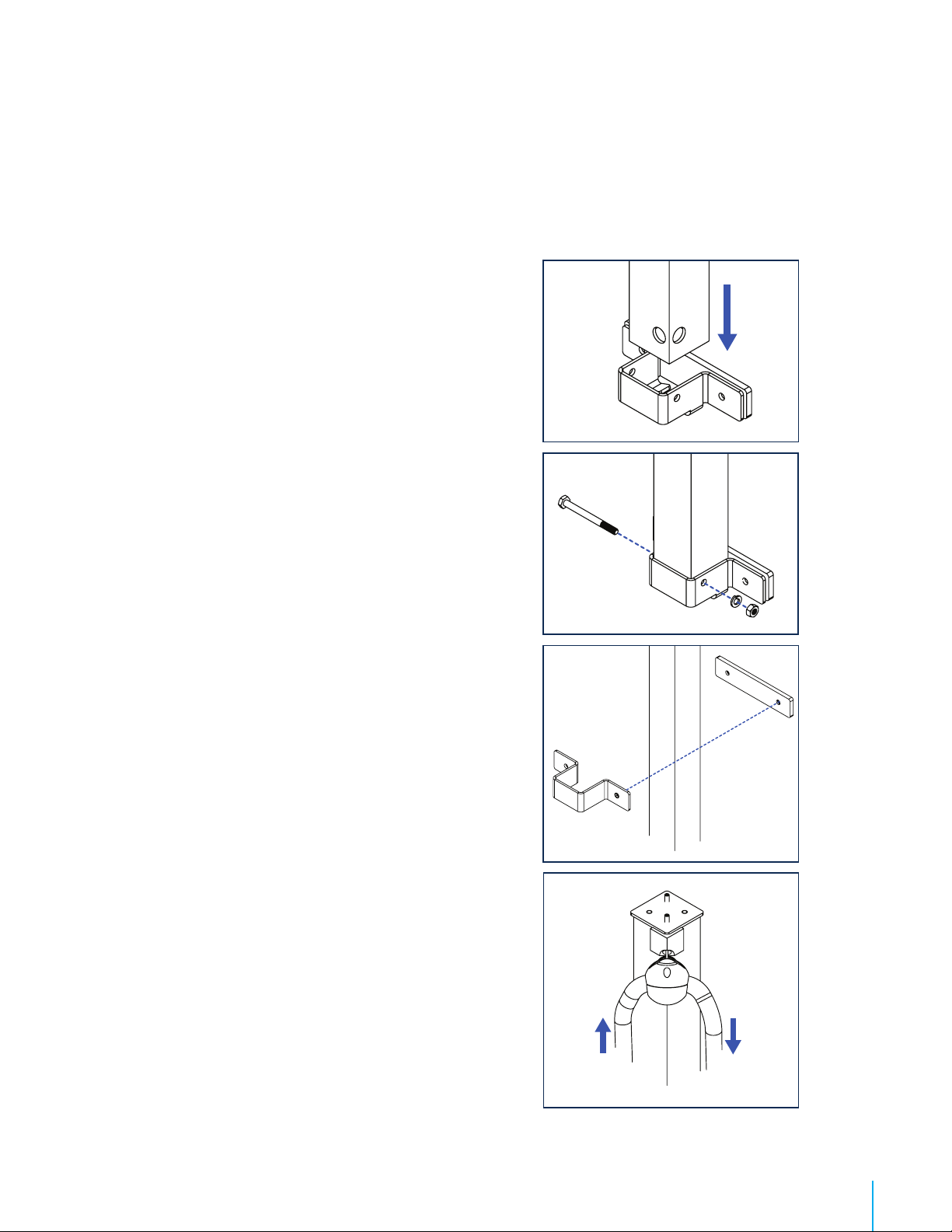
2. Sit the column in the lower wall mount bracket.
Remark : Make sure to position the Cable management
system’s cable clamp on the correct side, that is on the
right or the left, according to where the charging station is
located.
3. Secure the column by installing the screw and bolt in
the lower wall mount bracket thought the pre drilled
holes with a ratchet wrench and an axel nut socket
(the security screw that was used for holding the
counterweight).
4. Install the top bracket and the rectangular spacing
shim while inserting the column between the parts.
Once you ensure that the bracket is flush with
the plate and assembly is level, secure it with the
appropriate screws (according to wall type).
5. Verify the column’s angle with a level.
6. Proceed with the positioning of the cable clamp. Refer
to page 15.
7. Pull on the Cable management system’s cable a few
times to ensure that all parts are moving freely.
CoRe+TM
Cable management system and pedestal installation guide
8
Single charging station installation
Included material Qty
Cable management system columns and cable clamp 1
Empty column 1
Column mount bracket 2
Round spacing shims 2
Rectangular spacing shims 2
Self-adhesive rubber band 1
¼-20 screws (1’’) (for pre-drilled pedestal) 6
Self-drilling screws (1’’) (for pedestal with no holes) 6
Drilling template 1
Drilling template (bottom pedestal)1
IF THE PEDESTAL IS NOT PRE-DRILLED, USE THE FOLLOWING DRILLING TEMPLATES:
Top Drilling template
MEC-CST-00280
Bottom Drilling template
MEC-CST-00278
CoRe+TM
Cable management system and pedestal installation guide
9
BEFORE GETTING STARTED
! When unpackaging the Cable management system, make sure to remove the
security screw used to hold the counterweight during transport.
¡
Installing on a new single charging station.
First, install the pedestal and the charging station. Refer to CoRe+ MC
Installation Guide for pedestal and CoRe+
MC Installation Guide respectively. Then, install the Cable management system
as indicated below. If the pedestal is pre-drilled, use the ¼-20 screws provided
in the package. Otherwise, use the drilling template and self-drilling screws also
included with the kit. Refer to the illustration on the former page to know where
to place the template on the pedestal, and mark the holes to drill.
¡ Installing on an existing single charging station.
Drill holes that will be used to install the mount bracket for the column with the Cable
management system and the empty column. Use the drilling template and the self-drilling
screws provided with the kit. Refer to the illustration on the former page to know where to place
the template on the pedestal, and mark the holes to drill.
Cable management
system installation
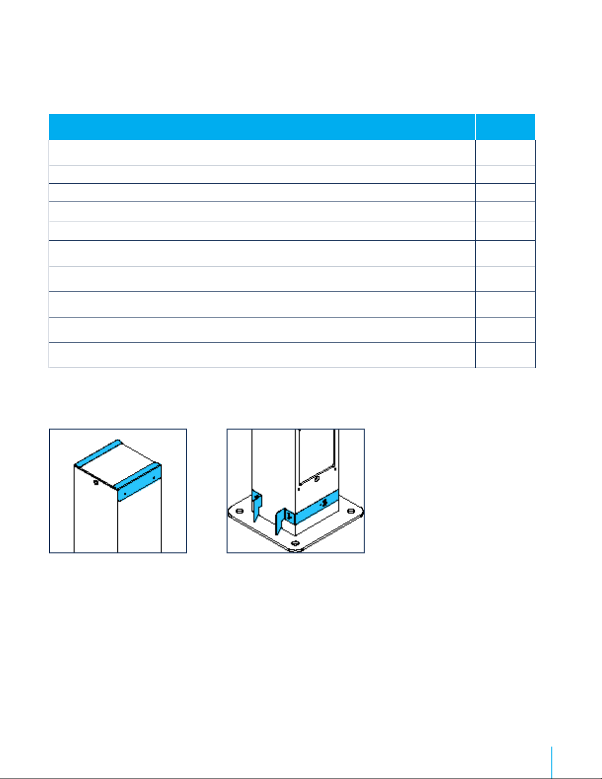
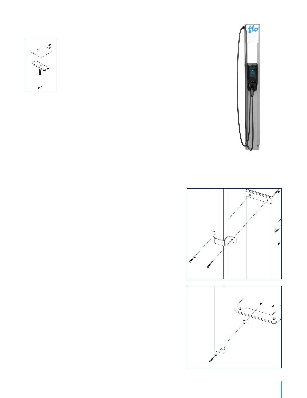
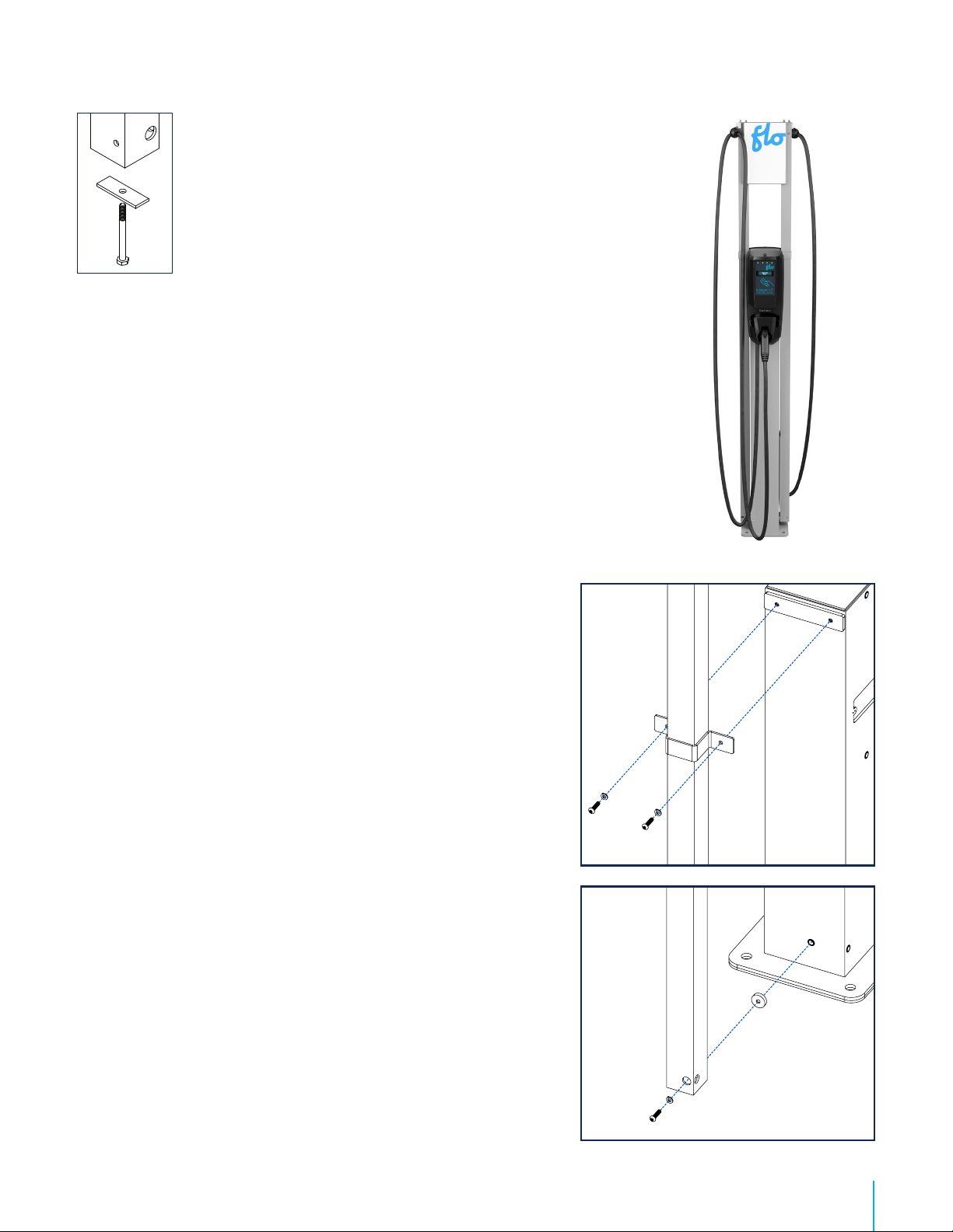
1. Install the rectangular spacing shim, place the column
and than install the upper mount bracket on top.
Screw parts loosely with ¼-20 or self-drilling screws,
depending on the type of pedestal you have, so the
Cable management system column is maintained in
place and moves freely to install the lower mounting
hardware.
Recommendation : To position the column, when
standing in front of the charging station, make sure to
place the output of the Cable management on the exterior
side.
2. Screw the column of the Cable management system
by placing the round spacing shim (circled in red in
the image included) between the pedestal and the
column, and tighten the screws to solidly secure the
column.
3. Secure the top bracket.
4. Install the empty column on the opposite side of the
charging station by following the above steps 1 to 3.
5. Proceed with the positioning of the cable clamp. Refer
to page 15.
6. Install the poster panel. Refer to page 16.
Caution : This pedestal is certied like an electrical enclosure,
and any alteration must comply with local regulation.

CoRe+TM
Cable management system and pedestal installation guide
10
Dual back-to-back charging
station installation
IF THE PEDESTAL IS NOT PRE-DRILLED, USE THE FOLLOWING DRILLING TEMPLATES:
Top Drilling template
MEC-CST-00280
Bottom Drilling template
MEC-CST-00278
Included material Qty
Cable management system columns and cable clamp 2
Top mounting brackets 2
Round spacing shims 2
Rectangular spacing shims 2
Self-adhesive rubber band 2
¼-20 screws (1’’) (for pre-drilled pedestal) 6
Self-drilling screws (1’’) (for pedestal with no holes) 6
Drilling template 1
Drilling template (bottom pedestal)1
CoRe+TM
Cable management system and pedestal installation guide
11
BEFORE GETTING STARTED
! When unpackaging the Cable management system, make sure to remove
the security screw used to hold the counterweight during transport.
¡
Installing on new back-to-back dual charging stations.
First, install the pedestal and the two charging stations. Refer to CoRe+ MC
Installation Guide for piedestal and CoRe+ MC Installation Guide respectively.
Then, install the Cable management system as indicated below. If the pedestal
is pre-drilled, use the ¼-20 screws provided in the package. Otherwise, use the
drilling template and self-drilling screws also included with the kit. Refer to the
illustration on the former to know where to place the template on the pedestal,
and mark the holes to drill.
¡ Installing on existing back-to-back dual charging stations.
Drill holes that will be used to secure the Cable management system attachment hardware. Use
the drilling template and the self-drilling screws provided with the kit.
1. Install the rectangular spacing shim, place the column
and than install the upper mount bracket on top.
Screw parts loosely with ¼-20 or self-drilling screws,
depending on the type of pedestal you have, so the
Cable management system column is maintained in
place and moves freely to install the lower mounting
hardware.
Recommendation : To position the column, when
standing in front of the charging station, make sure to
place the output of the Cable management on the exterior
side.
2. Screw the column of the Cable management system
by placing the round spacing shim (circled in red in
the image included) between the pedestal and the
column, and tighten the screws to solidly secure the
column.
3. Secure the top bracket.
4. Install the empty column on the opposite side of the
charging station by following the above steps 1 to 3.
5. Proceed with the positioning of the cable clamp. Refer
to page 15.
6. Install the poster panel. Refer to page 16.
Caution : This pedestal is certied like an electrical enclosure,
and any alteration must comply with local regulation.
Cable management
system installation

CoRe+TM
Cable management system and pedestal installation guide
12
Dual side-to-side charging
station installation
IF THE PEDESTAL IS NOT PRE-DRILLED, USE THE FOLLOWING DRILLING TEMPLATES:
Top Drilling template
MEC-CST-00280
Bottom Drilling template
MEC-CST-00278
Included material Qty
Cable management system columns and cable clamp 2
Round spacing shims 2
Self-adhesive rubber band 2
¼-20 screws (1’’) (for pre-drilled pedestal) 6
Self-drilling screws (1’’) (for pedestal with no holes) 6
Drilling template (for pedestal with no holes) 1
Charging station mount brackets (V-shape mount) and ¼-20 screws 2
Flexible tube 2
Column mount brackets, ¼-20 screws and bolts 4
Back cover and screws 2
Drilling template (bottom pedestal) 1
Gasket 2
Rectangular spacing shims 2
CoRe+TM
Cable management system and pedestal installation guide
13
BEFORE GETTING STARTED
! When unpackaging the Cable management system, make sure to remove the security
screw used to hold the counterweight during transport.
¡
Installing new side-by-side charging stations
• First, install the pedestal. Refer to CoRe+ MC Installation Guide for pedestal.
• Then, prepare installation material for the side-by-side charging station mount
brackets and Cable management systems, and follow the instructions that are
indicated below.
• Finally, install the charging stations. Refer to CoRe+ MC Installation Guide.
• Installing on existing side-by-side charging stations
Caution : Before getting started, cut off the current to prevent an electric shock.
INSTALLATION ON PRE-INSTALLED CHARGING STATIONS
1. Remove both charging stations from the pedestal so that you can install the new side-by-side
charging station mount brackets and the two Cable management systems.
2. Remove the wiring as you will need to hook the charging stations to new wires.
3. Then, prepare installation material for the side-by-side charging station mount brackets and Cable
management systems, and follow the instructions that are indicated below.
4. Reinstall the charging station on the new brackets.
Allow 10" (30 cm) of additional electrical wiring to connect the new charging station
to the installation.
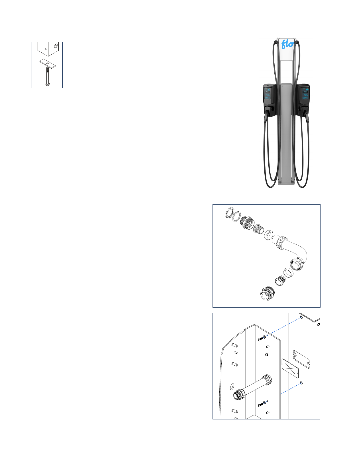
Side-to-side charging
station supports and cable
managements installation
1. Assemble the flexible tube.
2. Remove the plate giving you access to the electric wires at the bottom
of the pedestal and allow 30 cm (10 in) of extra wiring so to connect the
charging station once the flexible tube has been installed.
3. Screw the end of the flexible tube to the charging station mount bracket, on
the pedestal side.
4. Pass wires through the flexible tube.
5. Screw the rst charging station mount bracket to the pedestal* using the
holes provided for this purpose with the included screws, that is, the holes
that were used to secure the charging stations that were installed back-to-
back previously.
Caution : This pedestal is certied like an electrical enclosure, and any alteration must
comply with local regulation.
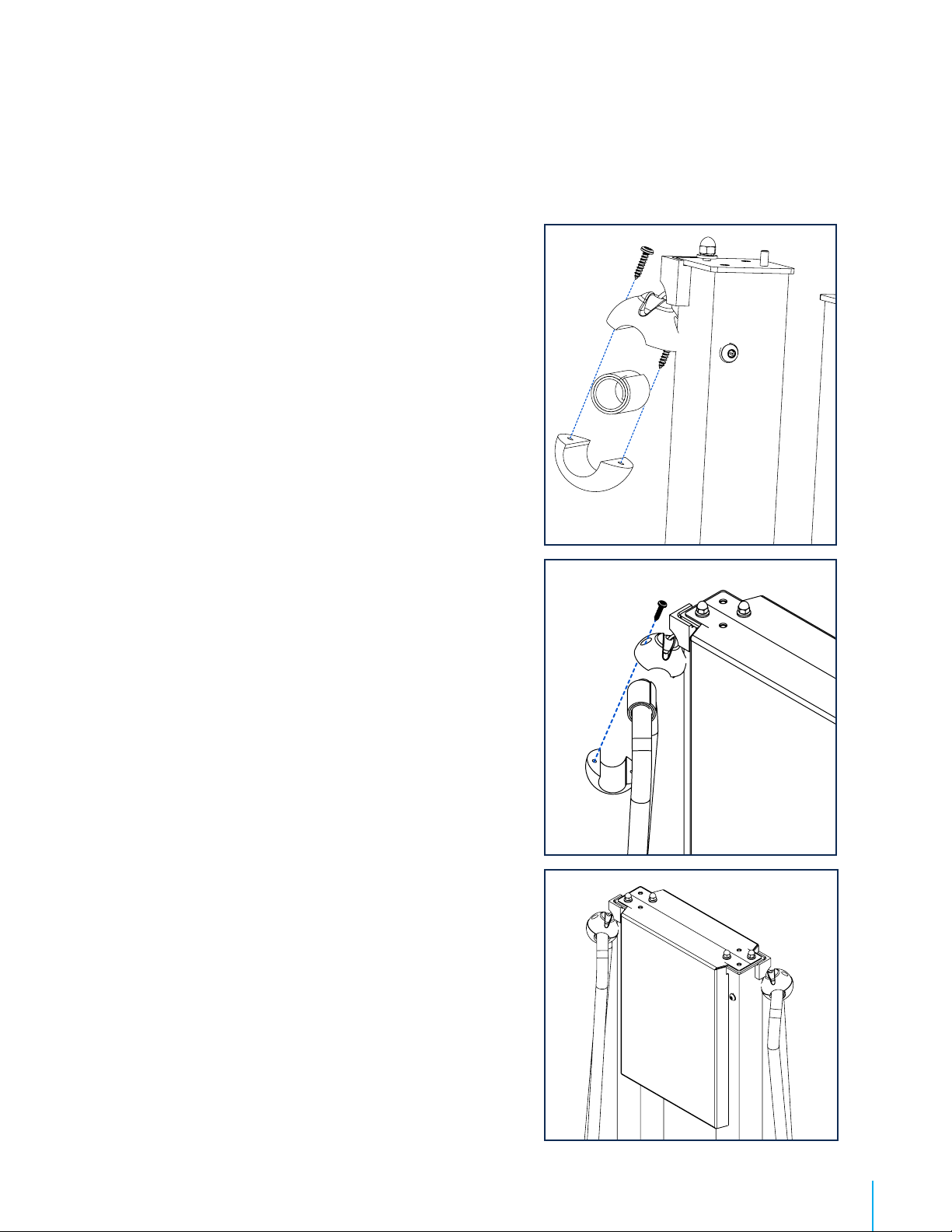
6. Place the column of the Cable management system inside the charging
station mount bracket, place tightly in the corner.
Recommendation : To position the column, when you stand in front of the
charging station, make sure to place the output (cable clamp) of the Cable
management system on the exterior side, and a gasket is inserted between the
pedestal and the back cover.
7. Screw the bottom column of the Cable management system by placing the
round spacing shim between the pedestal and the column, and tighten the
screws solidly to secure the column.

CoRe+TM
Cable management system and pedestal installation guide
14
8. Insert the other end of the flexible tube in the hole
provided for this purpose , and screw the bushing from
the exterior of the charging station mount bracket so to
maintain the flexible tube in place.
Remark : This will allow to hold the column during the
installation of the bottom column mount brackets.
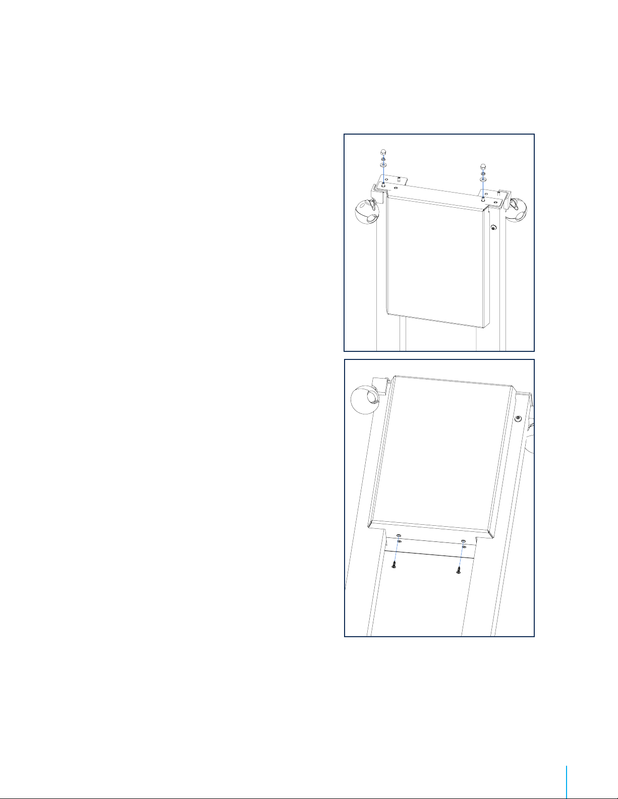
9. Install both column mount brackets starting with the 1st
assembly (1 on illustration) then proceed installing the 2nd
(2 on illustration).
Remarks : Each column mount bracket has a slot to make
its installation easier, which must be place on the front side
of the bracket, in other words on the side where the charging
station will be installed. Do not screws the bolts too tight
when placing the brackets so you can move them easily and
position them correctly. Once everything is well positioned,
tighten the bolts.
10. Secure the back cover in the column mount brackets
with the four screws.
Side-to-side charging station
supports and cable managements
installation
11. Install the second column on the opposite side of the
charging station by following the above steps 1 to 10.
12. Install or reinstall the charging stations. Refer to the
CoRe+ MC Installation Guide if need be.
13. Proceed with the positioning of the cable clamp. Refer to
page 15.
14. Install the poster panel. Refer to page 16.
1
2
CoRe+TM
Cable management system and pedestal installation guide
15
Positioning the cable clamp
1. Pull on the cable of the Cable management system to
hold the cable clamp in your hand.
2. Remove Torx screws.
3. Determine where to position the charging station cable
clamp.
Recommendation : The cable portion between the clamp
and the charging connector must not touch the ground when
the Cable management system is completely retracted. The
cable should hang about 2.5 in above the ground.
4. Apply the self-adhesive rubber band around the cable for
protection purposes. Set the clamp over the band and
reinsert the screws in it by adjusting the torque of your
tool to 7 in-lb.
5. Let the cable retract itself. Verify the clearing between
the charging station cable and the ground.
6. Roll the cable overhang around the charging station
cable holder.

CoRe+TM
Cable management system and pedestal installation guide
16
Positioning the poster panel
1. The top of the columns has embedded screws with rubber
caps and washers attached to them. Remove them and set
aside.
2. The poster panel is comprised of two parts. Before installing
it, secure the attachment plate to the base of one of the
panels with the screws provided. The plate is placed inside
the panel, and the screws are inserted inwards.
Matériel fourni / Included material Qty / Qté
Poster panel (including two sides) 2
Attachment plate and screws 1
Bolts 4
Washers 4
Rondelle de blocage / Split Lock Washer 4
CoRe+TM
Cable management system and pedestal installation guide
17
Positioning the poster panel
3. Place this panel on top of the columns by aligning the
panel holes with the embedded screws and secure the the
assembly.
4. Install the second panel as mentioned in step number 3,
and screw the attachment plate to assemble both panels
together.
5. Screw the bolts and washers on the second panel.
Remark : If you are installing a charging station “for private
use”, make sure to afx the self-adhesive label included for this
purpose.

CoRe+TM
Cable management system and pedestal installation guide
18
4
© 2014 ADDÉNERGIE TECHNOLOGIES INC. TOUS DROITS RÉSERVÉS Les informations et les spécications contenues dans ce document sont sujettes aux changements, modications et ajouts à n’importe quel moment et sans préavis.
© 2014 ADDÉNERGIE TECHNOLOGIES INC. ALL RIGHTS RESERVED Information and specications contained in this document are subject to change, amendments and additions at any time, without notice.
www
Spécications / Specications
Famille de produit / Product family: CoRe+TM
Modèle / Model: C+V1-PED-ADD
Révision / Revision: A
Info Compagnie / Company Info: AddÉnergie Technologies Inc.
Révision du document / Document revision number: 06
©2014 AddÉnergie Technologies Inc. Tous droits réservés. Ce matériel est protégé par les lois sur les droits
d’auteur de plusieurs pays et ne devrait pas être modié, reproduit ou distribué sans le consentement écrit
préallable de AddÉnergie Technologies.
©2014 AddÉnergie Technologies Inc. All Rights Reserved. This document is protected by copyright laws of
many countries and should not be modied, reproduced or distributed without the prior written consent of
AddÉnergie Technologies.
Spécications:
Plage de température d’opération : -40°C à+50°C
Étanchéité: NEMA 3R, pour utilisation extérieure
Poids à la livraison: approximativement 15 kg
Conformité aux normes de sécurité:
• UL 50 Issue: 2007/09/04 Ed:12 Rev: 2012/04/27 UL Standard for Safety Enclosures for Electrical Equipment,
Non-Environmental Considerations
• UL 50E Issue: 2007/09/04 Ed: 1 Rev: 2012/04/27 UL Standard for Safety Enclosures for Electrical Equipment,
Environmental Considerations
• CSA C22.2#94.1 Issued: 2007/09/04 Ed: 1 (R2012) Enclosures for Electrical Equipment, Non-Environmental
Considerations - General Instruction No.1: 2008/07/01
• CSA C22.2#94.2 Issue: 2007/09/04 Enclosures for Electrical Equipment Environmental Considerations;
General Instruction No. 1: 2008/07/01
Specications:
Ingress Protection rating: NEMA 3R enclosure, suitable for outdoor use.
Shipping weight: Approximately 15 kg
Security standard compliance:
• UL 50 Issue: 2007/09/04 Ed:12 Rev: 2012/04/27 UL Standard for Safety Enclosures for Electrical Equipment,
Non-Environmental Considerations
• UL 50E Issue: 2007/09/04 Ed: 1 Rev: 2012/04/27 UL Standard for Safety Enclosures for Electrical Equipment,
Environmental Considerations
• CSA C22.2#94.1 Issued: 2007/09/04 Ed: 1 (R2012) Enclosures for Electrical Equipment, Non-Environmental
Considerations - General Instruction No.1: 2008/07/01
• CSA C22.2#94.2 Issue: 2007/09/04 Enclosures for Electrical Equipment Environmental Considerations;
General Instruction No. 1: 2008/07/01
4009606
www
Pedestal Specications
Product family: CoRe+TM
Model: CO-PE-000002
Revision: A
Company Info: Flo Services Inc.
Document revision number: FLO_Installation_CoRe+_CableMgmt+Pedestal_US_12.2019_V11
©2019 AddÉnergie Technologies Inc. All Rights Reserved. This document is protected by
copyright laws of many countries and should not be modied, reproduced or distributed
without the prior written consent of AddÉnergie Technologies.
Specications:
Ingress Protection rating: NEMA 3R enclosure, suitable for outdoor use.
Shipping weight: Approximately 33 lbs
Security standard compliance:
• UL 50 Issue: 2007/09/04 Ed:12 UL Standard for Safety Enclosures for Electrical Equipment,
Non-Environmental Considerations
• UL 50E Issue: 2007/09/04 Ed: 1 UL Standard for Safety Enclosures for Electrical Equipment,
Environmental Considerations
• CSA C22.2#94.1 Issued: 2007/09/04 Ed: 1 (R2012) Enclosures for Electrical Equipment,
Non-Environmental Considerations - General Instruction No.1: 2008/07/01
• CSA C22.2#94.2 Issue: 2007/09/04 Enclosures for Electrical Equipment Environmental Considerations;
General Instruction No.1

CoRe+TM
Cable management system and pedestal installation guide
19
Maintenance and Safety
Carefully read this guide before installing the pedestal
1. This pedestal was designed to be ground-based, it must be mounted on a non-combustible surface.
2. This pedestal was designed to help meeting American Disability Act requirments.
3. Make sure with local authorities that the location where the pedestal is to be installed is free from underground
pipelines or electrical equipment, otherwise you might inflict yourself serious injuries.
4. Grounding: to ensure the safe operation of the pedestal, it must be connected to a grounding circuit compliant
with local regulations and installed by a certied electrician.
5. Communicate with a certied contractor, certied electrician or trained installer to ensure compliance with
local building code, regulation, security standards and weather conditions.
6. Handle parts with care, since they can be sharp-edged. Always use safety glasses and gloves when unpacking
and installing.
7. Some parts are heavy and could cause injuries. Use proper lifting techniques and wear safety boots at all times
during installation.
IMPORTANT SAFETY INSTRUCTIONS - PLEASE DO NOT DISCARD THESE INSTRUCTIONS
CoRe+TM
Cable management system and pedestal installation guide
20
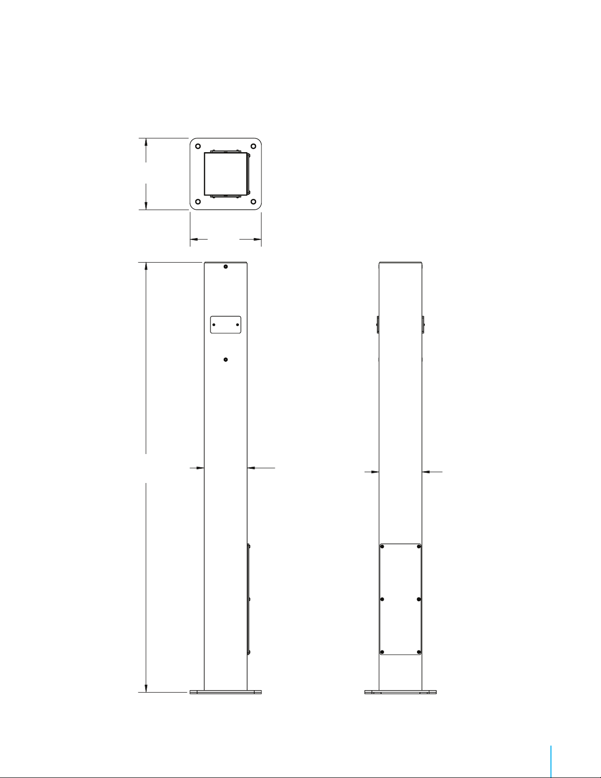
Dimensions
6
© 2014 ADDÉNERGIE TECHNOLOGIES INC. TOUS DROITS RÉSERVÉS
© 2014 ADDÉNERGIE TECHNOLOGIES INC. ALL RIGHTS RESERVED
Dimensions / Dimensions
132 cm
(52.125’’) 15.2 cm
(6’’)
15.2 cm
(6’’)
25.4 cm
(10’’)
25.4 cm
(10’’)
Other manuals for CoRe+
5
This manual suits for next models
1
Table of contents
Other Flo Batteries Charger manuals


