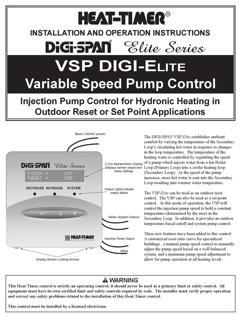
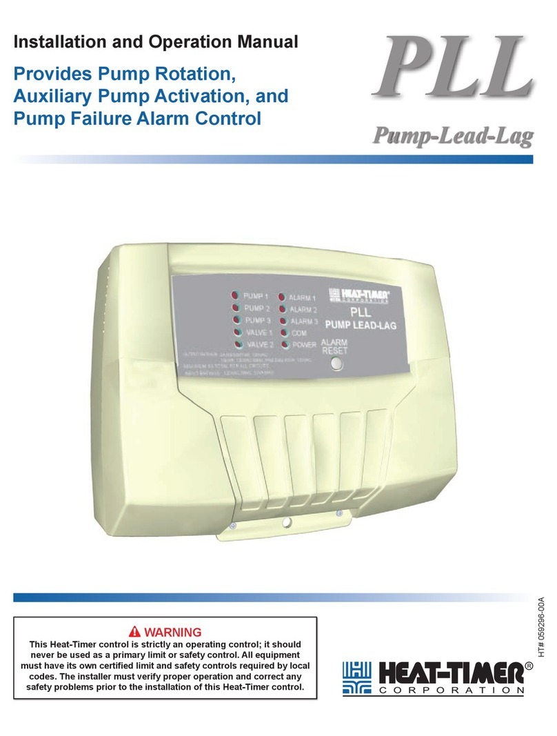
heat-timer Multi-MOD Platinum User manual

MULTI-MOD
Platinum
MADE IN U.S.A.
PREV.
SAFETY
GROUND
MUST BE
CONNECTED
OUT
TEMP
PROVE
/DHW
STAGE
A
STAGE
B
MENU FUNCTIONS
SELECT enters menus or accepts changes
ADJUST selects menu items or changes settings
BACK returns to previous menu
PREV./NEXT steps through stage status
STAGEHELP NEXT
PRESS TO
SELECT
BACK
SYS= 125oF OD= 31oF
ADJUST
A1
A2
A3
A4
A5
A6
A7
A8
A9
A10
A11
A12
STAGE
C
DO NOT APPLY ANY VOLTAGE
TO SENSOR TERMINALS
B1
B2
B3
B4
B5
B6
NETWORK
4-20 mA
SYSTEM
SHUTDOWN
SYSTEM
TEMP
INPUTS
ROUTE SENSOR AND AUXILIARY WIRES
THROUGH THIS KNOCKOUT ONLY
TGT= 126oF
<A> B C D
100% 50% --- ---
T
T
OUTPUT RATINGS:
120VAC, 6A RESISTIVE
1A PILOT DUTY
15A TOTAL
FOR ALL CIRCUITS
INPUT RATINGS:
115VAC 60Hz
30VA MAX
USE COPPER WIRE,
CLASS 1 WIRE ONLY
ENCLOSED
ENERGY
MANAGEMENT
EQUIPMENT
LISTED
99RA
STAGE selects stage menus or next stage
SYSTEM B C DA
LINE
NEUTRAL
SYS B C DA
1 2 3 4 5 6 7 8 9 10 11 12
FULL MODULATION
SEQUENCING CONTROL
LOCKOUT
INPUTS
STAGE
D
B7
B8
OPERATING LIMIT
OUTPUTS
SIGNAL
SHIELD
+
EMS
MODULATION OUTPUTS
A B C D
C1 C2 C3 C4 C5 C6 C7 C8 C9 C10 C11 C12
S
+
Multi-MOD
Platinum
HT# 059299-00 A

HT# 059299-00 A
Content 2
Multi-MoD PlatinuM overview 3
Standard Features 3
Optional Features 4
MoDulation ConCePt 4
unDerstanDing oPeration ConCePt 5
Reset Ratio/Outdoor Reset 5
Space Feedback Concept 6
initial Pilot PrograM 7
Make Sure You Have the Right Control 7
Multi-MoD PlatinuM FunCtion Chart 8
Multi-MoD PlatinuM BaCk Chart 9
extension FunCtion Chart 10
extension BaCk Chart 11
installation 12
Mounting the Enclosure 12
Activate the Battery 12
Remote Communication Wiring 12
BACnet MSTP or Modbus RS485 Wiring 12
Internet or BACnet IP Ethernet Wiring 13
Input Wiring 17
Outdoor sensor 17
System Sensor 17
4-20mA Temperature Sensor Wiring 18
Setback Wiring 20
Interfacing to MPC 20
Interfacing to HWR 20
Connecting Multi-MOD Platinum to Extensions 21
External Set Point Wiring 22
Connecting Internet communication 22
Connecting BACnet Communication 22
Connecting MODBUS Communication 22
Network Sensors Wiring 22
Modulating Output Card Installation 23
DisPlay 23
Button FunCtions 23
DisPlay stage MoDulation status 24
Display Messages 24
systeM startuP Menu 25
systeM startuP 26
Sensor Type 26
Sensor Type Table 26
System Temperature Sensor Type 26
EMS Input Mode 27
Stage Interface 27
DHW Set Point 29
Sensor Fault 29
Fast Cool Down 30
Day Light Saving 30
systeM settings Menu 31
systeM settings 32
Season 32
Set Point 32
Outdoor Cutoff Temperature 32
Outdoor Reset Settings 32
Reset Ratio 33
Target Offset 33
Minimum Target 33
Maximum Target 34
System Run-On 34
stage MoDulation 36
Gain 36
Purge Delay 36
Lag Delay 37
Standby Time 37
Last-Stage-Hold 37
Soft-off Delay 37
Modulation Speed 38
Lead Stage Rotation 38
Lead Stage 38
Lead Auto Rotate 38
stage settings 39
Stage Menu 39
Moving Around the Stages Menus 39
Mode 39
Ignition % 40
Modulation Start 40
Copy Settings (Stage A Only) 41
sCheDules Menu 42
Schedules 42
Shift 42
Day/Night Schedule 43
Copy Schedule 44
Set Date and Time 44
Vacation Schedule Setting 44
CoMMuniCation Menu 45
Internet Communication 45
Space Lockout 45
Day and Night Target 46
Space Feedback Gain 46
BACnet Communication 46
Modbus Communication 46
MaintenanCe Menu 47
System and Outdoor Sensor Trim 47
Stage Output Trim 47
seCurity 48
Password Enabled 48
Password Change 48
reset Control to FaCtory DeFaults 48
trouBleshooting 49
sPeCiFiCations 51
Multi-MOD Platinum Specications 51
Extension Module Specications 51
wiring DiagraMs 52
warranty 58

HT# 059299-00 A
The Multi-MOD Platinum is a multi-boiler modulating control It uses PID logic in addition to overlapping
the lead and lag boiler modulation, its patent logic, to achieve a smooth modulation and efcient system
performance It is capable of modulating 4 on board boilers When used with extensions panels it can
connect to a total of 20 modulating boilers Up to two external extensions can be used, each connecting to
8 modulating boilers The Multi-MOD Platinum is used in a variety of applications including building heating
and process applications
The Multi-MOD Platinum can operate in heating or cooling applications
When connected to a temperature sensor and an outdoor sensor, the Multi-MOD Platinum
can change the target based on the outdoor temperature (Outdoor Reset) or it can
modulate the boilers to maintain a xed set point See "Sensor Type" on page 26
The Multi-MOD Platinum can operate in a temperature or pressure environment to
maintain a set point For high temperature applications it can connect to 4-20mA
temperature sensors See "Sensor Type" on page 26
It accurately modulate motors using any of the 0-5V, 0-10V, 1-5V, 2-10V, 4-20 mA, or
0-135Ω modulating signals It can also modulate a combination of boilers with different
modulating signals See "Output Type" on page 27
The Multi-MOD Platinum now has a built-in 7-day schedule Each day has 4 day and 4
night time settings See "Schedules" on page 42
The Multi-MOD Platinum can accept setback input from external controls to lower the
target Set Point See "Setback Wiring" on page 20 and "Setback" on page 35
The Boost raises the building space temperature to day levels quicker It does that by
raising the target water temperature before the rst day schedule See "Boost and Early
Shutdown" on page 34
This feature allows the user to temporarily switch the control from Night Time settings to
Day Time settings or visa versa See "Shift" on page 42
The outdoor sensor is used to turn all the outputs off whenever the outdoor temperature
rises above the outdoor Cutoff value See "Outdoor Cutoff Temperature" on page 32
The Multi-MOD Platinum operation can be turned off during off-season using the Season
setting See "Season" on page 32
The control has three modes of rotation: Manual, Last-On, or Automatic The Automatic
option rotates the stages based on time See "Lead Stage Rotation" on page 38
Use Normal (PID) logic for slow responding systems as in heating systems Use Process
in fast responding systems See "Modulating Mode" on page 28
Any stage can be set to be a standby boiler (backup boiler) A Standby boiler will only run
after the rest of the boilers reach full re and remain at it for the Standby Delay period
See "Standby Time" on page 37
This input checks for component status before activating any stage It can be used to
check the combustion air damper or ow switch status See "Prove Wiring" on page 19
This input turns off the heating from a remote location See "Shutdown Wiring" on page 18
This output can be used to activate a system pump, combustion air damper, or perform
any other function that is required before any stage is activated
The control offers multiple DHW Priority options See "Prove/DHW Mode" on page 28
The Multi-MOD Platinum can accept a remote 4-20 mA set point signal See "External
Set Point Wiring" on page 22
The Gain adjusts the aggressiveness of the modulation See "Gain" on page 36
This feature is used primarily to reduce boiler short cycling The Last Stage Hold
maintains the system on longer and off longer See "Last-Stage-Hold" on page 37
The Multi-MOD Platinum is equipped with a password that is used to stop unauthorized
user from changing any of the control settings See "Security" on page 48

HT# 059299-00 A
The Internet communication option gives remote access to the control from
any computer with a web browser The access is through Heat-Timer ICMS
web site Internet ready controls have the capability to connect to a large
number of network sensors These sensors can be space, temperature,
pressure, oil tank levels, and many more Furthermore, the Internet option
adds history graphing, export reports to e-mail, and alarming that is delivered
by e-mail, web, and text messaging See "Internet Communication" on page
45
The Multi-MOD Platinum can be upgraded to communicate over BACnet IP
or MSTP networks All Multi-MOD Platinum functions can be monitored from
a remote location See BACnet Communication Upgrade Manual
The Multi-MOD Platinum can be upgraded to communicate over Modbus
RTU networks All Multi-MOD Platinum functions can be monitored from a
remote location See Modbus Communication Upgrade Manual
When the Multi-MOD Platinum is equipped with Internet communication,
it can connect to a large number of wireless and wired space sensors It
uses the space average temperature to regulate the building heat for better
comfort control and fuel savings See "Space Feedback Concept" on page 6
The Multi-MOD Platinum modulates the boilers to achieve the smoothest operation and highest system
efciency It does that by overlapping the lead and lag boiler operation The concept depends on the
Ignition % and the Modulation Start %
20%
20%
Purge
60%
100%
20%
20%
100%
Boiler A Modulating
Boiler B Modulating
Purge
Boiler B
MODULATING CONCEPT
SETTINGS:
Ignition % = 20%
Modulation Start % = 60%
Lag boiler drop= 40% x 60% = 24%
Modulation Increasing
Boiler A
20% 100%
20%
20%
24%
20%
Lead Boiler A remain
at 20% until System
Sensor exceeds Target
Lag Boiler B remains
at Ignition % while Lead
Boiler A modulates down Decrease Modulation
Boiler A
Boiler B
When the control needs to start heating, it activates the System output In most cases, this output operates
a system pump or a combustion air damper Then, the control checks the safety components operation
status by checking the Prove input for closure If the Prove signal was shorted, the control starts the
lead boiler Purge Whenever a boiler is activated, it must rst go through the Purge period See "Purge
Delay" on page 36 During Purge the control sets the boiler modulation to the lowest ring rate set by the
Ignition % See "Ignition %" on page 40 After the Purge ends, the control starts to modulate the lead boiler
gradually Whenever, the lead boiler reaches its Modulation Start %, the control starts the lag boiler Purge
See "Modulation Start" on page 40 After the lead boiler reaches its full capacity, the lag boiler may start its
upward modulation This process repeats for each additional lag boiler or until the system is satised

HT# 059299-00 A
20%
20%
Purge
60%
100%
20%
20%
100%
Boiler A Modulating
Boiler B Modulating
Purge
Boiler B
MODULATING CONCEPT
SETTINGS:
Ignition % = 20%
Modulation Start % = 60%
Lag boiler drop= 40% x 60% = 24%
Modulation Increasing
Boiler A
20% 100%
20%
20%
24%
20%
Lead Boiler A remain
at 20% until System
Sensor exceeds Target
Lag Boiler B remains
at Ignition % while Lead
Boiler A modulates down Decrease Modulation
Boiler A
Boiler B
When the load is reduced, the control will gradually decrease the lag boiler's modulation until it reaches its
lowest ring % The lag boiler will remain at the Ignition % while the control is reducing the lead boiler's
modulation When the lead boiler reaches 40% of the Modulation Start %, the control turns off the lag
boiler
The Multi-MOD Platinum has multiple operating modes that
satisfy most hydronic or steam systems When used to control
a hydronic system, it can change the target Set Point based
on outdoor temperature (Outdoor Reset) or it can modulate its
stages to achieve a xed Set Point
In Outdoor Reset, the Multi-MOD Platinum controls a hot water
heating system to provide a building with comfortable and even
heat levels It varies the temperature of the circulating heating
water in response to changes in the outdoor temperature The
heating water temperature is controlled through the modulation of
the stages
The Multi-MOD Platinum also controls the system-circulating
pump with an adjustable Outdoor Cutoff When the outdoor
temperature is above Outdoor Cutoff, the pump is off and no
heating water is circulated through the system When the outdoor
temperature drops below the Outdoor Cutoff, the system pump
output is activated and the heating water circulates through the
system The temperature of the heating water is controlled by the
Reset Ratio, Offset, Minimum Target, Maximum Target, and the
outdoor temperature
Reset Ratio (Outdoor : Water)
70 60 50 40 2030 0 -1010 -20
100
120
110
130
140
150
160
180
170
190
200
210
220
Water Temperature (in °F)
Reset Ratio Curves
Outdoor Temperature (in °F)
1:1.25
1:1
1.25:1
1.5:1
2:1
3:1
4:1
1:4 1:3 1:2 1:1.5
When a building is being heated, heat escapes through the walls,
doors, and windows to the colder outside air The colder the
outside temperature, the more heat escapes If you can input
heat into the building at the same rate that it is lost out of the
building, then the building temperature will remain constant The
Reset Ratio is an adjustment that lets the building achieve this
equilibrium between heat input and heat loss Outdoor reset is
the most efcient way a building can be heated

HT# 059299-00 A
The starting reset ratio for most systems is the 100 (OD):100
(SYS) (Outdoor Temperature : Heating Water Temperature) ratio
This means that for every degree the outdoor temperature drops,
the temperature of the heating water will increase one degree
The starting point of the ratio is adjustable, but comes factory
set to 70°F Outdoor Temperature and 100°F Water Temperature
For example with a 100 (OD):100 (SYS) ratio, if the outdoor
temperature is 50°F, this means that the outdoor temperature has
fallen 20° from the starting point of 70°F Therefore, the heating
water temperature will increase 20° to 120°F (100°F + 20°F)
When controlling a none-condensing
boiler directly without the use of a
mixing valve, minimum boiler water
temperature must be set to boiler
manufacturer specifications In that
case, system temperature must not go
below such temperature
Each building has different heat loss characteristics A very well
insulated building will not lose much heat to the outside air, and
may need a Reset Ratio of 200 (OD):100 (SYS) (Outdoor :
Water) This means that the outdoor temperature would have
to drop 2° to increase the water temperature 1 degree On the
other hand, a poorly insulated building with insufcient radiation
may need a Reset Ratio of 100 (OD):200 (SYS) This means
that for each degree the outdoor temperature drops the water
temperature will increase 2° The Multi-MOD Platinum has
a full range of Reset Ratios to match any buildings heat loss
characteristics
A heating curve that relies not only on Outdoor temperature but
also on type of radiation will improve the comfort See the Building
Suggested Settings table for different types of radiation based on
an average building insulation and heat loss The contractor can
ne-tune these settings to the specic building need
Radiators (Steel & Cast
Iron) 100 : 100 0˚F
Baseboard (Finned copper
tube& Cast Iron) 100 : 100 0˚F
Radiant (High Mass/
Concrete) 400 : 100 -10˚F
Radiant (Low Mass/Joists) 200 : 100 -10˚F
Fan Coils & Air Handlers 100 : 100 20˚F
A Multi-MOD Platinum control that is equipped with Internet
communication is capable of using Heat-Timer space sensors to
ne-tune its outdoor reset operation while providing signicant
savings The Multi-MOD Platinum adjusts the target water
temperature based on the Space Feedback Gain and the
difference between the current Space Average and the Space
target Example: Using a Space Feedback Gain of 4, if the
Space Average is 70°F and the day target is set to 72°F, the
control will add 4° to the System Target temperature for every 1°
(ambient temperature) the Space Average is below the Space
Target In this example, it would add 8° to the target water
temperature to compensate for the 2° reduction in the Space
Average See "Space Feedback Gain" on page 47
If the Space temperature exceeded the Space Target by 2°
while the target water temperature is at the Minimum Target
temperature for an hour, the control will turn the boilers off until
the Space Average drops below the Space Target

HT# 059299-00 A
Setting an Initial Pilot Program eases the installation and conguration of the Multi-MOD Platinum and gives
the opportunity to use many of the energy saving features while providing comfort
The program should consist of the following:
• Select the features that your system can utilize,
• Making sure you are ordering the right control and accessories (Multi-MOD Platinums do not come with
sensors or stage relays, these items must be ordered separately,
• Install and wire the Control,
• Set the System Startup menu,
• Set the System Settings,
• Set the Stages and their rotation,
• Set the Schedules
• Adjust the Reset Ratio and Water Offset (In Reset Mode Only) or set the Set Point,
The following are for communication equipped controls only:
• If the control had communication, connect and install the communication,
• If the control had Internet communication, install and wire the sensors
If you need the Multi-MOD Platinum to do additional tasks that either is not listed or do not know
how to congure them, contact Heat-Timer Corp Sales Department either by Phone (973)575-4004,
E-mail to: support@heat-timercom, or using the web contact form http://wwwheat-timercom

HT# 059299-00 A
MULTI-MOD
Platinum
MADE IN U.S.A.
PREV.
SAFETY
GROUND
MUST BE
CONNECTED
OUT
TEMP
PROVE
/DHW
STAGE
A
STAGE
B
MENU FUNCTIONS
SELECT enters menus or accepts changes
ADJUST selects menu items or changes settings
BACK returns to previous menu
PREV./NEXT steps through stage status
STAGEHELP NEXT
PRESS TO
SELECT
BACK
SYS= 125oF OD= 31oF
ADJUST
A1
A2
A3
A4
A5
A6
A7
A8
A9
A10
A11
A12
STAGE
C
DO NOT APPLY ANY VOLTAGE
TO SENSOR TERMINALS
B1
B2
B3
B4
B5
B6
NETWORK
4-20 mA
SYSTEM
SHUTDOWN
SYSTEM
TEMP
INPUTS
ROUTE SENSOR AND AUXILIARY WIRES
THROUGH THIS KNOCKOUT ONLY
TGT= 126oF
<A> B C D
100% 50% --- ---
T
T
OUTPUT RATINGS:
120VAC, 6A RESISTIVE
1A PILOT DUTY
15A TOTAL
FOR ALL CIRCUITS
INPUT RATINGS:
115VAC 60Hz
30VA MAX
USE COPPER WIRE,
CLASS 1 WIRE ONLY
ENCLOSED
ENERGY
MANAGEMENT
EQUIPMENT
LISTED
99RA
STAGE selects stage menus or next stage
SYSTEM B C DA
LINE
NEUTRAL
SYS B C DA
1 2 3 4 5 6 7 8 9 10 11 12
FULL MODULATION
SEQUENCING CONTROL
LOCKOUT
INPUTS
STAGE
D
B7
B8
OPERATING LIMIT
OUTPUTS
SIGNAL
SHIELD
+
EMS
MODULATION OUTPUTS
A B C D
C1 C2 C3 C4 C5 C6 C7 C8 C9 C10 C11 C12
S
+
Green Ground screw
must be connected
to Earth Ground
120VAC
Power
System Output controls
pumps, dampers, valves or
other system components.
Each output is wired in series
with each unit’s limit circuit.
The modulation outputs can be
voltage (0-5V, 0-10V, 1-5V, 2-10V,
4-20ma, or 135Ω). Different output boards
mount on the back of the Multi-MOD
to determine the output type.
If a unit is in Lockout,
the MultiMOD will not
consider it an active
To System Temp sensor
mounted in common header
4-20mA power sourcing
input for pressure and
temperature sensors
When closed, all heat
outputs are turned off*
To Heat-Timer network
sensors (Not MSI)**
* DRY CONTACTS ONLY
** Only available with the Remote Communications package
Checks status of system
components or DHW Call*
Depress the knob to go to menu and
accept changes. Rotate the knob to
scroll and change settings.
Depress the button to view the date and
time or to go back through the menus
The digital display shows the system status,
set point, lead stage <in brackets>, and
status of each stage.
To Outdoor sensor
Provides remote set
point adjustment with
a 4-20mA signal or
provides a setback
function
LEDs indiate each
output relay status
Button functions vary
Each active stage must
have a relay installed.
Relays must be
ordered separately
(HT# 500054-00)

HT# 059299-00 A
N
5V
8V
CPU Board
Battery
Ethernet
RS485
Main Board
Control Stages
A & B
Control Stages
C & D
A1
G1
B1
A2
G2
B2
RS485
Communication Board
(HT# 900234-20-XXX)
Fuse
Battery
HT#020002-00
Ethernet (RJ45) connects to:
• Internet
• BACnet IP Green RS485 connects to:
• MSI HUB interface
RS485 connects to
Extensions only.
Cables are provided with
Extension
Modulating Output Cards:
• 135Ω Output Card (HT# 900203-135)
• Current and Volt Output Cards
(HT# 900203-C/V)
Black RS485 connects to:
• BACnet MSTP
• Modbus RTU
• Network Manager

HT# 059299-00 A
ENCLOSED
ENERGY
MANAGEMENT
EQUIPMENT
LISTED
99RA
LOCKOUT
INPUTS
B1
B2
B3
B4
B5
B6
B7
B8
B9
B10
B11
B12
B13
B14
B15
B16
E F G H I J K L
MODUALTION OUTPUTS MODUALTION OUTPUTS
C1 C2 C3 C4 C5 C6 C7 C8 C9 C10 C11 C12 C13 C14 C15 C16 C17 C18 C19 C20 C21 C22 C23 C24
- + +
- + +
- + +
- + +
MADE IN U.S.A.
SAFETY
GROUND
MUST BE
CONNECTED
EXTENSION
MODULE
C O R P O R A T I O N
R
POWER COMMUNICATION
STAGE
ACTIVE
OUTPUT RATINGS:
120VAC, 6A RESISTIVE
1A PILOT DUTY
15A TOTAL
FOR ALL CIRCUITS
Lockout
Lockout
E
F
G
H
I
J
K
L
E
F
G
H
I
J
K
L
INPUT RATINGS:
115VAC 60Hz
30VA MAX
USE COPPER WIRE,
CLASS 1 WIRE ONLY
LINE
NEUTRAL
1
2
3
4
5
6
7
8
9
10
11
12
13
14
15
16
Serial No.:
OPERATING
LIMIT OUTPUTS
E
F
G
H
I
J
K
L
Relay
Outputs*
* DRY CONTACT ONLY
Communication LED
Blinks on good
communication
Power LED
will be ON
Green Earth
Ground screw
120VAC
Power
Burner Modulating
Outputs. Not used
with the HWRQ
Lockout
Inputs *
Stage LED is O
when relay is
energized

HT# 059299-00 A
1 2 3 4 5 6 7 8
On
Control Stages
1 & 2
Control Stages
3 & 4
Control Stages
5 & 6
Control Stages
7 & 8
Modulating Output Cards:
• 135Ω Output Card (HT# 900203-135)
• Current and Volt Output Cards
(HT# 900203-C/V)
Fuse
RS485 connects to
(MMOD, HWRQ, or
MPCQ Platinum)
Dip Switches
determine Extension
number
EXT1 Dip1=ON, DIP2=ON
EXT2 Dip1=OFF, DIP2=ON

HT# 059299-00 A
• Select a location near the equipment to be
controlled
• The surface should be at, sufciently wide, and
strong enough to hold the Multi-MOD
• Installation location should be away from extreme
heat, cold, or humidity
• Remove the control from its enclosure by removing
the top center screw and loosening the two bottom
screws
• Screw the enclosure to the surface through the
mounting holes in the back of the enclosure
• Return the panel to the enclosure Replace the top
screw and tighten the bottom two screws
Use existing the Enclosure Knockouts
DRILLING HOLES THROUGH THE CONTROL
ENCLOSURE VOIDS CONTROL WARRANTY
Mounting Holes
Communication
Knockout
Wiring
Knockouts
Enclosure
Lock
• Turn the Multi-MOD Platinum panel over to reveal the
piggyback circuit board (CPU board)
• Remove the plastic strap the covers the battery The contacts
should be touching the battery
Do not install the battery unless you plan to power the control at once
If the control is not powered, the battery will lose its charge in 100 days
N
5V
8V
CPU Board
Battery
Ethernet
RS485
Main Board
Control Stages
A & B
Control Stages
C & D
A1
G1
B1
A2
G2
B2
RS485
Communication Board
(HT# 900234-20-XXX)
• If a control is ordered as a standard control, it can be eld
upgraded to have communication by adding the appropriate
upgrade kit A new CPU board and a communication board will
be included in any of the Upgrade Kits
Multi-MOD Internet Upgrade Kit 900204-20-RINet
Multi-MOD BACnet IP or MSTP Upgrade Kit 900204-20-BAC
Multi-MOD Modbus Upgrade Kit 900204-20-BUS
• All Communication to Modbus RTU or BACnet MSTP must use
the RS485 on the control's Communication Board
N
5V
8V
CPU Board
Battery
Ethernet
RS485
Main Board
Control Stages
A & B
Control Stages
C & D
A1
G1
B1
A2
G2
B2
RS485
Communication Board
(HT# 900234-20-XXX)
Connect to BACnet MSTP Network
or MODBUS RTU Network
RS485 Cable

HT# 059299-00 A
• The RS485 cable length must not exceed 3500 feet
• The RS485 cable must use one of the Platinum control’s
enclosure side knockouts Do not use bottom knockouts for
communication cabling
• Connect the RS485 cable coming from the BACnet MSTP or
Modbus network to the Black RS485 communication socket on
the back of the control’s Communication Board The terminals
are labeled ‘A1 (+)’, G1 (Ground), and ‘B1 (-)’
The RS485 Ground terminal (G) MUST be
connected to the BMS RS485 Ground
• The Ethernet cable must use one of the Platinum control’s
enclosure side knockouts Do not use bottom knockouts for
communication cabling
• For reliable communication, the maximum Ethernet cable run
must not exceed 200'
• Use only CAT-5E Ethernet cable or better when connecting
from the Internet Modem, router or the IP network to the
Ethernet RJ45 communication socket on the back of the
control’s Communication Board
Class 1 voltage wiring (low voltage) must use a different knockout
and conduit from any Class 2 voltage wiring (high voltage)
N
5V
8V
CPU Board
Battery
Ethernet
RS485
Main Board
Control Stages
A & B
Control Stages
C & D
A1
G1
B1
A2
G2
B2
RS485
Communication Board
(HT# 900234-20-XXX)
Connect to BACnet IP Network
or the Internet
CAT5-E Cable
• Bring the 120VAC power wires through the enclosure's bottom knockouts
• Connect the hot line to the Line terminal (1) and connect the neutral line to
the Neutral terminal (2) Connect the green screw to Earth Ground
• Heat-Timer recommends the installation of a surge suppressor and a
power switch before the power line connection
• Use a separate circuit breaker for the control Do not share the control power
with other major equipment, pumps and motors
• Output relays do not source any power A separate power source must be
used Use the output relay to enable or disable the equipment
• Output relays do not source any power If the equipment connected to an
output relay requires power, an external power source must be used
• To use an output, you must install a relay Relays must be ordered
separately (HT# 500054-00)
• Each output relay on the Multi-MOD is rated for 1 Amp (1/8 HP) at 120
VAC 60 Hz If higher relay rating is required, connect the equipment to an
external relay Use the Multi-MOD output relay to control the external relay
MULTI-MOD
Platinum
MADE IN U.S.A.
PREV.
(DEL)
SAFETY
GROUND
MUST BE
CONNECTED
OUT
TEMP
PROVE
/DHW
STAGE
A
STAGE
B
MENU FUNCTIONS
SELECT enters menus or accepts changes
ADJUST selects menu items or changes settings
BACK returns to previous menu
PREV./NEXT steps through stage status
DEL deletes schedule settings
STAGE
(DAY)
HELP NEXT
PRESS TO
SELECT
BACK
ADJUST
A1
A2
A3
A4
A5
A6
A7
A8
A9
A10
A11
A12
STAGE
C
DO NOT APPLY ANY VOLTAGE
TO SENSOR TERMINALS
B1
B2
B3
B4
B5
B6
NETWORK
PRESS
4-20 mA
SHUTDOWN
SYSTEM
TEMP
INPUTS
ROUTE SENSOR AND AUXILIARY WIRES
THROUGH THIS KNOCKOUT ONLY
<A> B C D
100% 50% --- ---
T
T
OUTPUT RATINGS:
120VAC, 6A RESISTIVE
1A PILOT DUTY
15A TOTAL
FOR ALL CIRCUITS
INPUT RATINGS:
115VAC 60Hz
30VA MAX
USE COPPER WIRE,
CLASS 1 WIRE ONLY
ENCLOSED
ENERGY
MANAGEMENT
EQUIPMENT
LISTED
99RA
STAGE selects stage menus or next stage
DAY selects next day
SYSTEM B C DA
LINE
NEUTRAL
SYS B C DA
1 2
3 4 5 6 7 8 9 10 11 12
FULL MODULATION
SEQUENCING CONTROL
LOCKOUT
INPUTS
STAGE
D
B7
B8
OPERATING LIMIT
OUTPUTS
SIGNAL
SHIELD
+
EMS
MODULATION OUTPUTS
ABCD
C1 C2 C3 C4 C5 C6 C7 C8 C9 C10 C11 C12
S
+
L
N
Earth
Ground
120VAC

HT# 059299-00 A
• The System output can be used to activate a pump, a pump starter, a
combustion air damper, or other equipment
• The Multi-MOD Platinum activates the System output whenever there is a
call for any of the stages The System output remains energized whenever
a stage is active
• The System output does not source any power A separate power source
is required for the equipment
• The System relay comes pre-installed
MULTI-MOD
Platinum
MADE IN U.S.A.
PREV.
(DEL)
SAFETY
GROUND
MUST BE
CONNECTED
OUT
TEMP
PROVE
/DHW
STAGE
A
STAGE
B
MENU FUNCTIONS
SELECT enters menus or accepts changes
ADJUST selects menu items or changes settings
BACK returns to previous menu
PREV./NEXT steps through stage status
DEL deletes schedule settings
STAGE
(DAY)
HELP NEXT
PRESS TO
SELECT
BACK
ADJUST
A1
A2
A3
A4
A5
A6
A7
A8
A9
A10
A11
A12
STAGE
C
DO NOT APPLY ANY VOLTAGE
TO SENSOR TERMINALS
B1
B2
B3
B4
B5
B6
NETWORK
PRESS
4-20 mA
SHUTDOWN
SYSTEM
TEMP
INPUTS
ROUTE SENSOR AND AUXILIARY WIRES
THROUGH THIS KNOCKOUT ONLY
<A> B C D
100% 50% --- ---
T
T
OUTPUT RATINGS:
120VAC, 6A RESISTIVE
1A PILOT DUTY
15A TOTAL
FOR ALL CIRCUITS
INPUT RATINGS:
115VAC 60Hz
30VA MAX
USE COPPER WIRE,
CLASS 1 WIRE ONLY
ENCLOSED
ENERGY
MANAGEMENT
EQUIPMENT
LISTED
99RA
STAGE selects stage menus or next stage
DAY selects next day
SYSTEM
B C DA
LINE
NEUTRAL
SYS
B C DA
1 2 3 4 5
6 7 8 9 10 11 12
FULL MODULATION
SEQUENCING CONTROL
LOCKOUT
INPUTS
STAGE
D
B7
B8
OPERATING LIMIT
OUTPUTS
SIGNAL
SHIELD
+
EMS
MODULATION OUTPUTS
ABCD
C1 C2 C3 C4 C5 C6 C7 C8 C9 C10 C11 C12
S
+
System Pump
L
N
120VAC
MULTI-MOD
Platinum
MADE IN U.S.A.
PREV.
(DEL)
SAFETY
GROUND
MUST BE
CONNECTED
OUT
TEMP
PROVE
/DHW
STAGE
A
STAGE
B
MENU FUNCTIONS
SELECT enters menus or accepts changes
ADJUST selects menu items or changes settings
BACK returns to previous menu
PREV./NEXT steps through stage status
DEL deletes schedule settings
STAGE
(DAY)
HELP NEXT
PRESS TO
SELECT
BACK
ADJUST
A1
A2
A3
A4
A5
A6
A7
A8
A9
A10
A11
A12
STAGE
C
DO NOT APPLY ANY VOLTAGE
TO SENSOR TERMINALS
B1
B2
B3
B4
B5
B6
NETWORK
PRESS
4-20 mA
SHUTDOWN
SYSTEM
TEMP
INPUTS
ROUTE SENSOR AND AUXILIARY WIRES
THROUGH THIS KNOCKOUT ONLY
<A> B C D
100% 50% --- ---
T
T
OUTPUT RATINGS:
120VAC, 6A RESISTIVE
1A PILOT DUTY
15A TOTAL
FOR ALL CIRCUITS
INPUT RATINGS:
115VAC 60Hz
30VA MAX
USE COPPER WIRE,
CLASS 1 WIRE ONLY
ENCLOSED
ENERGY
MANAGEMENT
EQUIPMENT
LISTED
99RA
STAGE selects stage menus or next stage
DAY selects next day
SYSTEM B C DA
LINE
NEUTRAL
SYS B C DA
1 2 3 4 5 6 7 8 9 10 11 12
FULL MODULATION
SEQUENCING CONTROL
LOCKOUT
INPUTS
STAGE
D
B7
B8
OPERATING LIMIT
OUTPUTS
SIGNAL
SHIELD
+
EMS
MODULATION OUTPUTS
ABCD
C1 C2 C3 C4 C5 C6 C7 C8 C9 C10 C11 C12
S
+
System Pump
L
N
120VAC
• If an outdoor sensor was used, the System output will remain active after
all the stages are turned off for as long as the outdoor temperature is below
the outdoor Cutoff See "Outdoor Cutoff Temperature" on page 32 If the
outdoor temperature rises 2° above the outdoor Cutoff, the System output
de-activates after it runs for the full Run-On period See "System Run-On"
on page 34
• If no outdoor sensor was used and after the last stage turns off, the System
output runs for the Run-On period before turning off
• The System output activated whenever the outdoor temperature drops
below the outdoor Cutoff
• When the outdoor temperature rises 2°F above the Outdoor Cutoff, the
System output will remain active for the Run-On, then turn off
• The Multi-MOD Platinum is designed to operate up to four boilers without
the addition of Extensions modules The Multi-MOD Platinum can connect
to a maximum of two Extension modules maximizing the number of stages
controlled to 20 Each Extension module can connect to a maximum of
eight stages
• Each of the Multi-MOD Platinum or extension stages has an activation
output in addition to the modulation output Each of the stage outputs has
an LED to show its status
• Some modulating boilers may require an activation signal The stage
activation output is used to provide this signal To use the stage activation
output, you must install a relay in the stage relay socket Relays must be
ordered separately (HT# 500054-00)
• Each output relay on the Multi-MOD is rated for 1 Amp at 120 VAC 60 Hz
• Wire the stage activation signal in series with the boiler limits
For proper operation set the Mode of any
unused stage to Off See "Mode" on page 39
MULTI-MOD
Platinum
MADE IN U.S.A.
PREV.
(DEL)
SAFETY
GROUND
MUST BE
CONNECTED
OUT
TEMP
PROVE
/DHW
STAGE
A
STAGE
B
MENU FUNCTIONS
SELECT enters menus or accepts changes
ADJUST selects menu items or changes settings
BACK returns to previous menu
PREV./NEXT steps through stage status
DEL deletes schedule settings
STAGE
(DAY)
HELP NEXT
PRESS TO
SELECT
BACK
ADJUST
A1
A2
A3
A4
A5
A6
A7
A8
A9
A10
A11
A12
STAGE
C
DO NOT APPLY ANY VOLTAGE
TO SENSOR TERMINALS
B1
B2
B3
B4
B5
B6
NETWORK
PRESS
4-20 mA
SHUTDOWN
SYSTEM
TEMP
INPUTS
ROUTE SENSOR AND AUXILIARY WIRES
THROUGH THIS KNOCKOUT ONLY
<A> B C D
100% 50% --- ---
T
T
OUTPUT RATINGS:
120VAC, 6A RESISTIVE
1A PILOT DUTY
15A TOTAL
FOR ALL CIRCUITS
INPUT RATINGS:
115VAC 60Hz
30VA MAX
USE COPPER WIRE,
CLASS 1 WIRE ONLY
ENCLOSED
ENERGY
MANAGEMENT
EQUIPMENT
LISTED
99RA
STAGE selects stage menus or next stage
DAY selects next day
SYSTEM
B C DA
LINE
NEUTRAL
SYS
B C DA
1 2 3 4
5 6 7 8 9 10 11 12
FULL MODULATION
SEQUENCING CONTROL
LOCKOUT
INPUTS
STAGE
D
B7
B8
OPERATING LIMIT
OUTPUTS
SIGNAL
SHIELD
+
EMS
MODULATION OUTPUTS
ABCD
C1 C2 C3 C4 C5 C6 C7 C8 C9 C10 C11 C12
S
+
Boiler1
Ativation Boiler3
Ativation
Boiler2
Ativation Boiler4
Ativation
Boiler
Activation

HT# 059299-00 A
• To have the Multi-MOD Platinum operate the boilers and their pumps, use
SPDT relays (Single-Pole Double-Throw) and TDR relays (Time-Delay
relay)
• The SPDT relay sends the activation signal from the Multi-MOD Platinum
stage activation output to the boiler Interlock (TT) and its pump
• The TDR relay receives the SPDT pump activation signal and send it to the
pump When the SPDT relay signal ends, the TDR keeps the pump running
for an additional period This additional delay acts as the Run-On delay
available for the System output See "System Run-On" on page 34
MULTI-MOD
Platinum
MADE IN U.S.A.
PREV.
(DEL)
SAFETY
GROUND
MUST BE
CONNECTED
OUT
TEMP
PROVE
/DHW
STAGE
A
STAGE
B
MENU FUNCTIONS
SELECT enters menus or accepts changes
ADJUST selects menu items or changes settings
BACK returns to previous menu
PREV./NEXT steps through stage status
DEL deletes schedule settings
STAGE
(DAY)
HELP NEXT
PRESS TO
SELECT
BACK
ADJUST
A1
A2
A3
A4
A5
A6
A7
A8
A9
A10
A11
A12
STAGE
C
DO NOT APPLY ANY VOLTAGE
TO SENSOR TERMINALS
B1
B2
B3
B4
B5
B6
NETWORK
PRESS
4-20 mA
SHUTDOWN
SYSTEM
TEMP
INPUTS
ROUTE SENSOR AND AUXILIARY WIRES
THROUGH THIS KNOCKOUT ONLY
<A> B C D
100% 50% --- ---
T
T
OUTPUT RATINGS:
120VAC, 6A RESISTIVE
1A PILOT DUTY
15A TOTAL
FOR ALL CIRCUITS
INPUT RATINGS:
115VAC 60Hz
30VA MAX
USE COPPER WIRE,
CLASS 1 WIRE ONLY
ENCLOSED
ENERGY
MANAGEMENT
EQUIPMENT
LISTED
99RA
STAGE selects stage menus or next stage
DAY selects next day
SYSTEM B C DA
LINE
NEUTRAL
SYS
B C DA
1 2 3
45 6 7 8 9 10 11 12
FULL MODULATION
SEQUENCING CONTROL
LOCKOUT
INPUTS
STAGE
D
B7
B8
OPERATING LIMIT
OUTPUTS
SIGNAL
SHIELD
+
EMS
MODULATION OUTPUTS
ABCD
C1 C2 C3 C4 C5 C6 C7 C8 C9 C10 C11 C12
S
+
SPDT
Relay 1
Boiler
Activation
Boiler1 Pump1
TDR
Relay 1
L N
120VAC
SPDT
Relay 2
Boiler2 Pump2
TDR
Relay 2
L N
120VAC
• The Multi-MOD Platinum can operate up to four 135 Ω modulating motors
(Multi-MOD ordered with 135-Ohm Output cards) Each 135 Ohm Output
card operates two stages See "Modulating Output Card Installation" on
page 23
• Terminals C1, C4, C7, and C10 on the Multi-MOD Platinum connects to the
modulation decreasing terminals on the burners (Blue/Black modulating
wires)
• Terminals C3, C6, C9, and C12 on the Multi-MOD Platinum connects to the
modulation increasing on the burners (White modulating wires)
• Terminals C2, C5, C8, and C11 on the Multi-MOD Platinum connects to the
modulation common terminals on the burners (Red modulating wires)
MULTI-MOD
Platinum
MADE IN U.S.A.
PREV.
(DEL)
SAFETY
GROUND
MUST BE
CONNECTED
OUT
TEMP
PROVE
/DHW
STAGE
A
STAGE
B
MENU FUNCTIONS
SELECT enters menus or accepts changes
ADJUST selects menu items or changes settings
BACK returns to previous menu
PREV./NEXT steps through stage status
DEL deletes schedule settings
STAGE
(DAY)
HELP NEXT
PRESS TO
SELECT
BACK
ADJUST
A1
A2
A3
A4
A5
A6
A7
A8
A9
A10
A11
A12
STAGE
C
DO NOT APPLY ANY VOLTAGE
TO SENSOR TERMINALS
B1
B2
B3
B4
B5
B6
NETWORK
PRESS
4-20 mA
SHUTDOWN
SYSTEM
TEMP
INPUTS
ROUTE SENSOR AND AUXILIARY WIRES
THROUGH THIS KNOCKOUT ONLY
<A> B C D
100% 50% --- ---
T
T
OUTPUT RATINGS:
120VAC, 6A RESISTIVE
1A PILOT DUTY
15A TOTAL
FOR ALL CIRCUITS
INPUT RATINGS:
115VAC 60Hz
30VA MAX
USE COPPER WIRE,
CLASS 1 WIRE ONLY
ENCLOSED
ENERGY
MANAGEMENT
EQUIPMENT
LISTED
99RA
STAGE selects stage menus or next stage
DAY selects next day
SYSTEM B C DA
LINE
NEUTRAL
SYS B C DA
1 2 3 4 5 6 7 8 9 10 11 12
FULL MODULATION
SEQUENCING CONTROL
LOCKOUT
INPUTS
STAGE
D
B7
B8
OPERATING LIMIT
OUTPUTS
SIGNAL
SHIELD
+
EMS
MODULATION OUTPUTS
A B C D
C1 C2 C3 C4 C5 C6 C7 C8 C9 C10 C11 C12
S
+
Boiler1
135Ω
Signal
B R W
Boiler2
135Ω
Signal
B R W
Boiler4
135Ω
Signal
B R W
Boiler3
135Ω
Signal
B R W
Boiler 135Ω
Modulation Signal
B R W R W R W R WB B B
• The Multi-MOD Platinum can operate up to four 4-20 mA modulating
motors (Multi-MOD ordered with C/V (Current/Voltage) output cards) See
"Modulating Output Card Installation" on page 23
• To program the control for 4-20 mA output, See "Output Type" on page 27
• Apply the supplied label marked Current/Voltage below the modulating
terminals
• The Multi-MOD sources 24VDC excitation voltage for the 4-20mA signal

HT# 059299-00 A
• Terminals C2, C5, C8, and C11 on the Multi-MOD Platinum must be
connected to the modulation Signal (+) terminals on the burners
• Terminals C1, C4, C7, and C10 on the Multi-MOD Platinum must be
connected to the modulation Common terminals on the burners
MULTI-MOD
Platinum
MADE IN U.S.A.
PREV.
(DEL)
SAFETY
GROUND
MUST BE
CONNECTED
OUT
TEMP
PROVE
/DHW
STAGE
A
STAGE
B
MENU FUNCTIONS
SELECT enters menus or accepts changes
ADJUST selects menu items or changes settings
BACK returns to previous menu
PREV./NEXT steps through stage status
DEL deletes schedule settings
STAGE
(DAY)
HELP NEXT
PRESS TO
SELECT
BACK
ADJUST
A1
A2
A3
A4
A5
A6
A7
A8
A9
A10
A11
A12
STAGE
C
DO NOT APPLY ANY VOLTAGE
TO SENSOR TERMINALS
B1
B2
B3
B4
B5
B6
NETWORK
PRESS
4-20 mA
SHUTDOWN
SYSTEM
TEMP
INPUTS
ROUTE SENSOR AND AUXILIARY WIRES
THROUGH THIS KNOCKOUT ONLY
<A> B C D
100% 50% --- ---
T
T
OUTPUT RATINGS:
120VAC, 6A RESISTIVE
1A PILOT DUTY
15A TOTAL
FOR ALL CIRCUITS
INPUT RATINGS:
115VAC 60Hz
30VA MAX
USE COPPER WIRE,
CLASS 1 WIRE ONLY
ENCLOSED
ENERGY
MANAGEMENT
EQUIPMENT
LISTED
99RA
STAGE selects stage menus or next stage
DAY selects next day
SYSTEM B C DA
LINE
NEUTRAL
SYS B C DA
1 2 3 4 5 6 7 8 9 10 11 12
FULL MODULATION
SEQUENCING CONTROL
LOCKOUT
INPUTS
STAGE
D
B7
B8
OPERATING LIMIT
OUTPUTS
SIGNAL
SHIELD
+
EMS
MODULATION OUTPUTS
A B C D
C1 C2 C3 C4 C5 C6 C7 C8 C9 C10 C11 C12
S
+
Boiler1
4-20mA
Signal
+-
Boiler3
4-20mA
Signal
+-
Boiler2
4-20mA
Signal
+-
Boiler4
4-20mA
Signal
+-
Boiler 4-20mA
Modulation Signal
mA
Com mA
Com
mA
Com mA
Com
• The Multi-MOD Platinum can operate up to four voltage-modulating
motors (Multi-MOD ordered with C/V (Current Voltage) output cards) See
"Modulating Output Card Installation" on page 23
• The Multi-MOD Platinum can modulate any of the following voltage motors:
0-10V, 0-5V, 2-10BV, 1-5V See "Output Type" on page 27
• Apply the supplied label marked Current/Voltage below the modulating
terminals
• Terminals C1, C4, C7, and C10 on the Multi-MOD Platinum must be
connected to the modulation Ground terminals on the burners
• Terminals C3, C6, C9, and C12 on the Multi-MOD Platinum must be
connected to the modulation Voltage (V+) terminals on the burners
MULTI-MOD
Platinum
MADE IN U.S.A.
PREV.
(DEL)
SAFETY
GROUND
MUST BE
CONNECTED
OUT
TEMP
PROVE
/DHW
STAGE
A
STAGE
B
MENU FUNCTIONS
SELECT enters menus or accepts changes
ADJUST selects menu items or changes settings
BACK returns to previous menu
PREV./NEXT steps through stage status
DEL deletes schedule settings
STAGE
(DAY)
HELP NEXT
PRESS TO
SELECT
BACK
ADJUST
A1
A2
A3
A4
A5
A6
A7
A8
A9
A10
A11
A12
STAGE
C
DO NOT APPLY ANY VOLTAGE
TO SENSOR TERMINALS
B1
B2
B3
B4
B5
B6
NETWORK
PRESS
4-20 mA
SHUTDOWN
SYSTEM
TEMP
INPUTS
ROUTE SENSOR AND AUXILIARY WIRES
THROUGH THIS KNOCKOUT ONLY
<A> B C D
100% 50% --- ---
T
T
OUTPUT RATINGS:
120VAC, 6A RESISTIVE
1A PILOT DUTY
15A TOTAL
FOR ALL CIRCUITS
INPUT RATINGS:
115VAC 60Hz
30VA MAX
USE COPPER WIRE,
CLASS 1 WIRE ONLY
ENCLOSED
ENERGY
MANAGEMENT
EQUIPMENT
LISTED
99RA
STAGE selects stage menus or next stage
DAY selects next day
SYSTEM B C DA
LINE
NEUTRAL
SYS B C DA
1 2 3 4 5 6 7 8 9 10 11 12
FULL MODULATION
SEQUENCING CONTROL
LOCKOUT
INPUTS
STAGE
D
B7
B8
OPERATING LIMIT
OUTPUTS
SIGNAL
SHIELD
+
EMS
MODULATION OUTPUTS
A B C D
C1 C2 C3 C4 C5 C6 C7 C8 C9 C10 C11 C12
S
+
Boiler1
Voltage
Signal
+-
Boiler Voltage
Modulation Signal
Boiler3
Voltage
Signal
+-
Boiler2
Voltage
Signal
+-
Boiler4
Voltage
Signal
+-
V+
GND V+
GND V+
GND V+
GND
• The Multi-MOD Platinum can communicate to and modulate burners
equipped with the Siemens® LMV The LMV communicates over Modbus
networks See "Stage Interface" on page 27
• The LMV Interface communicates the boiler modulation from
the Multi-MOD Platinum to the Siemens® LMV burner control In
addition, it sends the boiler lockout information from the LMV to the
Multi-MOD Platinum Each burner must be connected to a LMV Interface
The LMV Interface must be purchased separately (HT #926621-00) In
addition, an Interface Power Supply (HT #926622-00) must be purchased
for every 10 LMV Interfaces
• See LMV Interface Manual for information on conguring and wiring to the
Siemens® LMV equipped burners

HT# 059299-00 A
• An outdoor sensor must be used when selecting Reset °F or
Reset °C The sensor is used to calculate the system target In
addition it is used in the outdoor Cutoff See "Sensor Type" on
page 26 and "Outdoor Cutoff Temperature" on page 32
• If an outdoor sensor is installed in any of the set point options,
it will only be used in the outdoor Cutoff This feature will
automatically be activated when an outdoor sensor is connected
• Use only the Outdoor Sensor included with the unit
(HT# 904220-00)
• Locate the sensor on the north side of the building at least 10'
above the ground The sensor MUST never be in direct sunlight
• Be sure the location is away from doors, windows, exhaust fans,
vents, or other possible heat or cool sources
• Adhere the Outdoor Label to the back of the sensor base
• Use the Enclosure Base bottom knockout for the conduit Use
the locknut to hold the conduit and enclosure base together
Install and screw the cover to the base
• If screws are used to afx the enclosure to the wall, make sure to
seal around the sensor and wall except from the bottom
Class 1 voltage wiring (low voltage)
must use a different knockout and
conduit from any Class 2 voltage
wiring (high voltage)
To avoid damage to the Multi-MOD,
NO VOLTAGE can be applied to the
Multi-MOD Platinum input terminals
Outdoor Sensor
snap-in location
Shield
not connected
Conduit
Outdoor Label
on back of Sensor
Outdoor Sensor
Mounting
screws
location
Seal around
sensor and wall
Outdoor
drip-hole
Conduit
Well
Sensor
in well
• Connect the sensor wires to the Out Temp terminals
Temperature sensors have no polarity
• Connect the shield to terminal A12 with one of the other sensor
wires Do not connect the shield at the sensor end
• The sensor wires can be extended up to 500’ using 18 AWG
2-conductor shielded cable (HT# 703001-01)
MULTI-MOD
Platinum
MADE IN U.S.A.
PREV.
(DEL)
SAFETY
GROUND
MUST BE
CONNECTED
OUT
TEMP
PROVE
/DHW
STAGE
A
STAGE
B
MENU FUNCTIONS
SELECT enters menus or accepts changes
ADJUST selects menu items or changes settings
BACK returns to previous menu
PREV./NEXT steps through stage status
DEL deletes schedule settings
STAGE
(DAY)
HELP NEXT
PRESS TO
SELECT
BACK
ADJUST
A1
A2
A3
A4
A5
A6
A7
A8
A9
A10
A11
A12
STAGE
C
DO NOT APPLY ANY VOLTAGE
TO SENSOR TERMINALS
B1
B2
B3
B4
B5
B6
NETWORK
PRESS
4-20 mA
SHUTDOWN
SYSTEM
TEMP
INPUTS
ROUTE SENSOR AND AUXILIARY WIRES
THROUGH THIS KNOCKOUT ONLY
<A> B C D
100% 50% --- ---
T
T
OUTPUT RATINGS:
120VAC, 6A RESISTIVE
1A PILOT DUTY
15A TOTAL
FOR ALL CIRCUITS
INPUT RATINGS:
115VAC 60Hz
30VA MAX
USE COPPER WIRE,
CLASS 1 WIRE ONLY
ENCLOSED
ENERGY
MANAGEMENT
EQUIPMENT
LISTED
99RA
STAGE selects stage menus or next stage
DAY selects next day
SYSTEM B C DA
LINE
NEUTRAL
SYS B C DA
1 2 3 4 5 6 7 8 9 10 11 12
FULL MODULATION
SEQUENCING CONTROL
LOCKOUT
INPUTS
STAGE
D
B7
B8
OPERATING LIMIT
OUTPUTS
SIGNAL
SHIELD
+
EMS
MODULATION OUTPUTS
ABCD
C1 C2 C3 C4 C5 C6 C7 C8 C9 C10 C11 C12
S
+
Shield Outdoor
Sensor
The Multi-MOD must be connected to a temperature or pressure
sensor The sensor connected must match the Sensor Type
selected in the Startup menu Sensors must be ordered separately
Outdoor Sensor
snap-in location
Shield
not connected
Conduit
Outdoor Label
on back of Sensor
Outdoor Sensor
Mounting
screws
location
Seal around
sensor and wall
Outdoor
drip-hole
Conduit
Well
Sensor
in well
• The Multi-MOD Platinum is designed to connect to a Heat-Timer
temperature sensor (HT# 904250-00) The sensor must be
inserted into a 3/8ID well (HT# 904011-00)
• Locate the sensor in the common header where it will register the
output before any takeoffs If the sensor cannot read the output
of all the stages, it will not be able to control the system properly

HT# 059299-00 A
• Attach the sensor wires to the Out Temp terminals (A11 and A12)
Temperature sensors have no polarity
• Connect the shield to terminal A12 with one of the other sensor
wires Do not connect the shield at the sensor end
• The sensor wires can be extended up to 500’ using shielded
2-conductor cable (#18/2)
MULTI-MOD
Platinum
MADE IN U.S.A.
PREV.
(DEL)
SAFETY
GROUND
MUST BE
CONNECTED
OUT
TEMP
PROVE
/DHW
STAGE
A
STAGE
B
MENU FUNCTIONS
SELECT enters menus or accepts changes
ADJUST selects menu items or changes settings
BACK returns to previous menu
PREV./NEXT steps through stage status
DEL deletes schedule settings
STAGE
(DAY)
HELP NEXT
PRESS TO
SELECT
BACK
ADJUST
A1
A2
A3
A4
A5
A6
A7
A8
A9
A10
A11
A12
STAGE
C
DO NOT APPLY ANY VOLTAGE
TO SENSOR TERMINALS
B1
B2
B3
B4
B5
B6
NETWORK
PRESS
4-20 mA
SHUTDOWN
SYSTEM
TEMP
INPUTS
ROUTE SENSOR AND AUXILIARY WIRES
THROUGH THIS KNOCKOUT ONLY
<A> B C D
100% 50% --- ---
T
T
OUTPUT RATINGS:
120VAC, 6A RESISTIVE
1A PILOT DUTY
15A TOTAL
FOR ALL CIRCUITS
INPUT RATINGS:
115VAC 60Hz
30VA MAX
USE COPPER WIRE,
CLASS 1 WIRE ONLY
ENCLOSED
ENERGY
MANAGEMENT
EQUIPMENT
LISTED
99RA
STAGE selects stage menus or next stage
DAY selects next day
SYSTEM B C DA
LINE
NEUTRAL
SYS B C DA
1 2 3 4 5 6 7 8 9 10 11 12
FULL MODULATION
SEQUENCING CONTROL
LOCKOUT
INPUTS
STAGE
D
B7
B8
OPERATING LIMIT
OUTPUTS
SIGNAL
SHIELD
+
EMS
MODULATION OUTPUTS
ABCD
C1 C2 C3 C4 C5 C6 C7 C8 C9 C10 C11 C12
S
+
Shield System
Temperature
Sensor
TGT= 126oF
SYS= 125oF OD= 31oF
• The Multi-MOD Platinum can connect to a 4-20mA temperature
sensor (HT# 904160-00) See "Sensor Type" on page 26
• Locate the temperature sensor on the main supply header where
it will register the output of all the stages If the sensor cannot
read the output of all the stages, the Multi-MOD Platinum will not
be able to control the stages properly
• 4-20mA Temperature Sensor wires can be extended up to 500' by
splicing with 18 gauge twisted pair wire
• Connect the sensor's Blue wire to terminal PRESS - A5 (S)
• Connect the sensor's Brown wire to terminal PRESS - A6 (+)
• Cut the rest of the transducer wires and tubes
MULTI-MOD
Platinum
MADE IN U.S.A.
PREV.
(DEL)
SAFETY
GROUND
MUST BE
CONNECTED
OUT
TEMP
PROVE
/DHW
STAGE
A
STAGE
B
MENU FUNCTIONS
SELECT enters menus or accepts changes
ADJUST selects menu items or changes settings
BACK returns to previous menu
PREV./NEXT steps through stage status
DEL deletes schedule settings
STAGE
(DAY)
HELP NEXT
PRESS TO
SELECT
BACK
ADJUST
A1
A2
A3
A4
A5
A6
A7
A8
A9
A10
A11
A12
STAGE
C
DO NOT APPLY ANY VOLTAGE
TO SENSOR TERMINALS
B1
B2
B3
B4
B5
B6
NETWORK
PRESS
4-20 mA
SHUTDOWN
SYSTEM
TEMP
INPUTS
ROUTE SENSOR AND AUXILIARY WIRES
THROUGH THIS KNOCKOUT ONLY
<A> B C D
100% 50% --- ---
T
T
OUTPUT RATINGS:
120VAC, 6A RESISTIVE
1A PILOT DUTY
15A TOTAL
FOR ALL CIRCUITS
INPUT RATINGS:
115VAC 60Hz
30VA MAX
USE COPPER WIRE,
CLASS 1 WIRE ONLY
ENCLOSED
ENERGY
MANAGEMENT
EQUIPMENT
LISTED
99RA
STAGE selects stage menus or next stage
DAY selects next day
SYSTEM B C DA
LINE
NEUTRAL
SYS B C DA
1 2 3 4 5 6 7 8 9 10 11 12
FULL MODULATION
SEQUENCING CONTROL
LOCKOUT
INPUTS
STAGE
D
B7
B8
OPERATING LIMIT
OUTPUTS
SIGNAL
SHIELD
+
EMS
MODULATION OUTPUTS
ABCD
C1 C2 C3 C4 C5 C6 C7 C8 C9 C10 C11 C12
S
+
TGT= 5 PSI
SYS= 4 PSI OD= 31oF
Brown (+)
Blue (-)
• The Multi-MOD Platinum is designed to connect to a pressure
transducer See "Sensor Type" on page 26
• Locate the transducer on the main supply header where it will
register the output of all the stages If the transducer cannot read
the output of all the stages, the Multi-MOD Platinum will not be
able to control the stages properly
• Attach the transducer to the steam header using a ¼" isolation
tube (pigtail) (HT# 135020-00)
• Pressure transducer wires can be extended up to 500' by splicing
with 18 gauge twisted pair wire
• Connect the Black wire from the pressure transducer to terminal
PRESS - A5 (S)
• Connect the Red wire from the pressure transducer to terminal
PRESS - A6 (+)
• Cut the rest of the transducer wires and tubes
MULTI-MOD
Platinum
MADE IN U.S.A.
PREV.
(DEL)
SAFETY
GROUND
MUST BE
CONNECTED
OUT
TEMP
PROVE
/DHW
STAGE
A
STAGE
B
MENU FUNCTIONS
SELECT enters menus or accepts changes
ADJUST selects menu items or changes settings
BACK returns to previous menu
PREV./NEXT steps through stage status
DEL deletes schedule settings
STAGE
(DAY)
HELP NEXT
PRESS TO
SELECT
BACK
ADJUST
A1
A2
A3
A4
A5
A6
A7
A8
A9
A10
A11
A12
STAGE
C
DO NOT APPLY ANY VOLTAGE
TO SENSOR TERMINALS
B1
B2
B3
B4
B5
B6
NETWORK
PRESS
4-20 mA
SHUTDOWN
SYSTEM
TEMP
INPUTS
ROUTE SENSOR AND AUXILIARY WIRES
THROUGH THIS KNOCKOUT ONLY
<A> B C D
100% 50% --- ---
T
T
OUTPUT RATINGS:
120VAC, 6A RESISTIVE
1A PILOT DUTY
15A TOTAL
FOR ALL CIRCUITS
INPUT RATINGS:
115VAC 60Hz
30VA MAX
USE COPPER WIRE,
CLASS 1 WIRE ONLY
ENCLOSED
ENERGY
MANAGEMENT
EQUIPMENT
LISTED
99RA
STAGE selects stage menus or next stage
DAY selects next day
SYSTEM B C DA
LINE
NEUTRAL
SYS B C DA
1 2 3 4 5 6 7 8 9 10 11 12
FULL MODULATION
SEQUENCING CONTROL
LOCKOUT
INPUTS
STAGE
D
B7
B8
OPERATING LIMIT
OUTPUTS
SIGNAL
SHIELD
+
EMS
MODULATION OUTPUTS
ABCD
C1 C2 C3 C4 C5 C6 C7 C8 C9 C10 C11 C12
S
+
Cut the rest of
wires and tubes
Connect to
1/4" pigtail
Black (-)
Red (+)
Transducer
4-20mA
TGT= 5 PSI
SYS= 4 PSI OD= 31oF
• The Shutdown is used to turn off the control remotely It can be
congured for Normally Open (Shutdown) or Normally Closed
(TSTAT)
• If boilers are running and he shutdown termnal is closed remotely
all active stages will modulate down to low re (Ignition %) They
will remain there until the adjustable Soft-Off period has nished
See page 37 for Soft-Off
• The System output will remain active until the Run-On Delay
ends, then it will also turn off See "System Run-On" on page 34
MULTI-MOD
Platinum
MADE IN U.S.A.
PREV.
(DEL)
SAFETY
GROUND
MUST BE
CONNECTED
OUT
TEMP
PROVE
/DHW
STAGE
A
STAGE
B
MENU FUNCTIONS
SELECT enters menus or accepts changes
ADJUST selects menu items or changes settings
BACK returns to previous menu
PREV./NEXT steps through stage status
DEL deletes schedule settings
STAGE
(DAY)
HELP NEXT
PRESS TO
SELECT
BACK
ADJUST
A1
A2
A3
A4
A5
A6
A7
A8
A9
A10
A11
A12
STAGE
C
DO NOT APPLY ANY VOLTAGE
TO SENSOR TERMINALS
B1
B2
B3
B4
B5
B6
NETWORK
PRESS
4-20 mA
SHUTDOWN
SYSTEM
TEMP
INPUTS
ROUTE SENSOR AND AUXILIARY WIRES
THROUGH THIS KNOCKOUT ONLY
<A> B C D
100% 50% --- ---
T
T
OUTPUT RATINGS:
120VAC, 6A RESISTIVE
1A PILOT DUTY
15A TOTAL
FOR ALL CIRCUITS
INPUT RATINGS:
115VAC 60Hz
30VA MAX
USE COPPER WIRE,
CLASS 1 WIRE ONLY
ENCLOSED
ENERGY
MANAGEMENT
EQUIPMENT
LISTED
99RA
STAGE selects stage menus or next stage
DAY selects next day
SYSTEM B C DA
LINE
NEUTRAL
SYS B C DA
1 2 3 4 5 6 7 8 9 10 11 12
FULL MODULATION
SEQUENCING CONTROL
LOCKOUT
INPUTS
STAGE
D
B7
B8
OPERATING LIMIT
OUTPUTS
SIGNAL
SHIELD
+
EMS
MODULATION OUTPUTS
ABCD
C1 C2 C3 C4 C5 C6 C7 C8 C9 C10 C11 C12
S
+
Shutdown
Dry Contact
To avoid damage to the Multi-MOD,
NO VOLTAGE can be applied to the
Multi-MOD Platinum input terminals

HT# 059299-00 A
• The System Prove feature is provided to check the system
component operation status before activating any stages Prove
must be selected from the Prove/DHW Startup option See
"Prove/DHW Mode" on page 28
• A typical use of this feature is to check for water ow before ring
any boiler stages When there is a call for heat, the System
Output relay activates the system pump When the pump
establishes ow, a ow switch closes the Prove input terminals
Only then, can the Multi-MOD Platinum activate and modulate the
boilers as required to hold the set point
• If the Prove input is open on a call for a stage, the Multi-MOD
Platinum will enable only the System output All stage outputs
will be off when the Prove input is open
• A factory installed jumper provides the System Prove signal Do
not remove the jumper unless it is replaced by a Prove signal
MULTI-MOD
Platinum
MADE IN U.S.A.
PREV.
(DEL)
SAFETY
GROUND
MUST BE
CONNECTED
OUT
TEMP
PROVE
/DHW
STAGE
A
STAGE
B
MENU FUNCTIONS
SELECT enters menus or accepts changes
ADJUST selects menu items or changes settings
BACK returns to previous menu
PREV./NEXT steps through stage status
DEL deletes schedule settings
STAGE
(DAY)
HELP NEXT
PRESS TO
SELECT
BACK
ADJUST
A1
A2
A3
A4
A5
A6
A7
A8
A9
A10
A11
A12
STAGE
C
DO NOT APPLY ANY VOLTAGE
TO SENSOR TERMINALS
B1
B2
B3
B4
B5
B6
NETWORK
PRESS
4-20 mA
SHUTDOWN
SYSTEM
TEMP
INPUTS
ROUTE SENSOR AND AUXILIARY WIRES
THROUGH THIS KNOCKOUT ONLY
<A> B C D
100% 50% --- ---
T
T
OUTPUT RATINGS:
120VAC, 6A RESISTIVE
1A PILOT DUTY
15A TOTAL
FOR ALL CIRCUITS
INPUT RATINGS:
115VAC 60Hz
30VA MAX
USE COPPER WIRE,
CLASS 1 WIRE ONLY
ENCLOSED
ENERGY
MANAGEMENT
EQUIPMENT
LISTED
99RA
STAGE selects stage menus or next stage
DAY selects next day
SYSTEM B C DA
LINE
NEUTRAL
SYS B C DA
1 2 3 4 5 6 7 8 9 10 11 12
FULL MODULATION
SEQUENCING CONTROL
LOCKOUT
INPUTS
STAGE
D
B7
B8
OPERATING LIMIT
OUTPUTS
SIGNAL
SHIELD
+
EMS
MODULATION OUTPUTS
ABCD
C1 C2 C3 C4 C5 C6 C7 C8 C9 C10 C11 C12
S
+
Prove Input
Dry Contact
Do not remove the factory installed
Prove jumper unless it is replaced
by a prove signal If the Prove input
is not closed/shorted, the Multi-MOD
Platinum will NOT activate the stages
The Prove input cannot be used as
a safety limit All equipment must
have its own certified limit and safety
controls as required by code
• The DHW Call feature is used to raise the system Target to the
DHW Set Point In addition, it regulates the operation of the
System output The System output operation varies based on
the DHW Priority setting selected from the Startup menu See
"Prove/DHW Mode" on page 28
• Wire a DHW aquastat to the DHW Call terminals The call must
be dry-contact
• Remove the jumper on the DHW terminals for proper operation
MULTI-MOD
Platinum
MADE IN U.S.A.
PREV.
(DEL)
SAFETY
GROUND
MUST BE
CONNECTED
OUT
TEMP
PROVE
/DHW
STAGE
A
STAGE
B
MENU FUNCTIONS
SELECT enters menus or accepts changes
ADJUST selects menu items or changes settings
BACK returns to previous menu
PREV./NEXT steps through stage status
DEL deletes schedule settings
STAGE
(DAY)
HELP NEXT
PRESS TO
SELECT
BACK
ADJUST
A1
A2
A3
A4
A5
A6
A7
A8
A9
A10
A11
A12
STAGE
C
DO NOT APPLY ANY VOLTAGE
TO SENSOR TERMINALS
B1
B2
B3
B4
B5
B6
NETWORK
PRESS
4-20 mA
SHUTDOWN
SYSTEM
TEMP
INPUTS
ROUTE SENSOR AND AUXILIARY WIRES
THROUGH THIS KNOCKOUT ONLY
<A> B C D
100% 50% --- ---
T
T
OUTPUT RATINGS:
120VAC, 6A RESISTIVE
1A PILOT DUTY
15A TOTAL
FOR ALL CIRCUITS
INPUT RATINGS:
115VAC 60Hz
30VA MAX
USE COPPER WIRE,
CLASS 1 WIRE ONLY
ENCLOSED
ENERGY
MANAGEMENT
EQUIPMENT
LISTED
99RA
STAGE selects stage menus or next stage
DAY selects next day
SYSTEM B C DA
LINE
NEUTRAL
SYS B C DA
1 2 3 4 5 6 7 8 9 10 11 12
FULL MODULATION
SEQUENCING CONTROL
LOCKOUT
INPUTS
STAGE
D
B7
B8
OPERATING LIMIT
OUTPUTS
SIGNAL
SHIELD
+
EMS
MODULATION OUTPUTS
ABCD
C1 C2 C3 C4 C5 C6 C7 C8 C9 C10 C11 C12
S
+
DHW Call
Dry Contact
• The Multi-MOD Platinum will not activate or modulate any Stage
in Lockout A Lockout signal tells the Multi-MOD Platinum that
the related stage is encountering a problem and cannot be
started The Stage display status will show (L/O)
• However, using the Lockout will drastically improve the control's
set point management
• There is a Lockout input for each stage on the Multi-MOD
Platinum and Extension Module
• The Lockout signal must be a dry-contact closure from the boiler
No voltage can be placed across the terminals If the source of
the signal has voltage, use a relay
MULTI-MOD
Platinum
MADE IN U.S.A.
PREV.
(DEL)
SAFETY
GROUND
MUST BE
CONNECTED
OUT
TEMP
PROVE
/DHW
STAGE
A
STAGE
B
MENU FUNCTIONS
SELECT enters menus or accepts changes
ADJUST selects menu items or changes settings
BACK returns to previous menu
PREV./NEXT steps through stage status
DEL deletes schedule settings
STAGE
(DAY)
HELP NEXT
PRESS TO
SELECT
BACK
ADJUST
A1
A2
A3
A4
A5
A6
A7
A8
A9
A10
A11
A12
STAGE
C
DO NOT APPLY ANY VOLTAGE
TO SENSOR TERMINALS
B1
B2
B3
B4
B5
B6
NETWORK
PRESS
4-20 mA
SHUTDOWN
SYSTEM
TEMP
INPUTS
ROUTE SENSOR AND AUXILIARY WIRES
THROUGH THIS KNOCKOUT ONLY
<A> B C D
100% 50% --- ---
T
T
OUTPUT RATINGS:
120VAC, 6A RESISTIVE
1A PILOT DUTY
15A TOTAL
FOR ALL CIRCUITS
INPUT RATINGS:
115VAC 60Hz
30VA MAX
USE COPPER WIRE,
CLASS 1 WIRE ONLY
ENCLOSED
ENERGY
MANAGEMENT
EQUIPMENT
LISTED
99RA
STAGE selects stage menus or next stage
DAY selects next day
SYSTEM B C DA
LINE
NEUTRAL
SYS B C DA
1 2 3 4 5 6 7 8 9 10 11 12
FULL MODULATION
SEQUENCING CONTROL
LOCKOUT
INPUTS
STAGE
D
B7
B8
OPERATING LIMIT
OUTPUTS
SIGNAL
SHIELD
+
EMS
MODULATION OUTPUTS
ABCD
C1 C2 C3 C4 C5 C6 C7 C8 C9 C10 C11 C12
S
+
Boiler 1
Lockout
Boiler 2
Lockout
Boiler 3
Lockout
Boiler 4
Lockout
Do not use the Lockout inputs as a
safety check All equipment must
have their certified limit and safety
controls installed as required by code

HT# 059299-00 A
• The Setback is used to reduce the system target when less load
is required during the night or on the weekends when a building is
unoccupied, but a minimum level of heat is still required
• To use the Setback, the EMS Input mode must be set to Setback
See "EMS Input Mode" on page 27 Also, the Setback value must
be greater than 0 See "Setback" on page 35
• The Setback can be activated based on the Night Schedule
settings or an external dry-contact Setback input
• When using an external Setback, wire the dry-contact Setback
signal to the EMS terminals (+) and (SIGNAL)
• When the Setback terminals are shorted, the Setback is enabled
and the Multi-MOD Platinum will hold the lower Set Point The
main display will show "Setback to: 150F" to indicate this
condition
• When the setback signal ends, the Multi-MOD Platinum will revert
to the higher target setting
To avoid damage to the Multi-MOD,
NO VOLTAGE can be applied to the
Multi-MOD Platinum input terminals
MULTI-MOD
Platinum
MADE IN U.S.A.
PREV.
(DEL)
SAFETY
GROUND
MUST BE
CONNECTED
OUT
TEMP
PROVE
/DHW
STAGE
A
STAGE
B
MENU FUNCTIONS
SELECT enters menus or accepts changes
ADJUST selects menu items or changes settings
BACK returns to previous menu
PREV./NEXT steps through stage status
DEL deletes schedule settings
STAGE
(DAY)
HELP NEXT
PRESS TO
SELECT
BACK
ADJUST
A1
A2
A3
A4
A5
A6
A7
A8
A9
A10
A11
A12
STAGE
C
DO NOT APPLY ANY VOLTAGE
TO SENSOR TERMINALS
B1
B2
B3
B4
B5
B6
NETWORK
PRESS
4-20 mA
SHUTDOWN
SYSTEM
TEMP
INPUTS
ROUTE SENSOR AND AUXILIARY WIRES
THROUGH THIS KNOCKOUT ONLY
<A> B C D
100% 50% --- ---
T
T
OUTPUT RATINGS:
120VAC, 6A RESISTIVE
1A PILOT DUTY
15A TOTAL
FOR ALL CIRCUITS
INPUT RATINGS:
115VAC 60Hz
30VA MAX
USE COPPER WIRE,
CLASS 1 WIRE ONLY
ENCLOSED
ENERGY
MANAGEMENT
EQUIPMENT
LISTED
99RA
STAGE selects stage menus or next stage
DAY selects next day
SYSTEM B C DA
LINE
NEUTRAL
SYS B C DA
1 2 3 4 5 6 7 8 9 10 11 12
FULL MODULATION
SEQUENCING CONTROL
LOCKOUT
INPUTS
STAGE
D
B7
B8
OPERATING LIMIT
OUTPUTS
SIGNAL
SHIELD
+
EMS
MODULATION OUTPUTS
ABCD
C1 C2 C3 C4 C5 C6 C7 C8 C9 C10 C11 C12
S
+
Setback Input
Dry Contact
• The MPC Platinum is a steam cycling outdoor reset control
• The MPC Platinum can be used to activate and deactivate
the Multi-MOD Platinum Shutdown terminals First, the MPC
Platinum Option 2 Relay Mode must be set to Inverse of Output
See MPC Platinum Manual
• Wire the MPC Platinum Option 2 output terminals 15 and 16 to
the Multi-MOD Platinum Shutdown input terminals A3 and A4
MULTI-MOD
Platinum
MADE IN U.S.A.
PREV.
(DEL)
SAFETY
GROUND
MUST BE
CONNECTED
OUT
TEMP
PROVE
/DHW
STAGE
A
STAGE
B
MENU FUNCTIONS
SELECT enters menus or accepts changes
ADJUST selects menu items or changes settings
BACK returns to previous menu
PREV./NEXT steps through stage status
DEL deletes schedule settings
STAGE
(DAY)
HELP NEXT
PRESS TO
SELECT
BACK
ADJUST
A1
A2
A3
A4
A5
A6
A7
A8
A9
A10
A11
A12
STAGE
C
DO NOT APPLY ANY VOLTAGE
TO SENSOR TERMINALS
B1
B2
B3
B4
B5
B6
NETWORK
PRESS
4-20 mA
SHUTDOWN
SYSTEM
TEMP
INPUTS
ROUTE SENSOR AND AUXILIARY WIRES
THROUGH THIS KNOCKOUT ONLY
<A> B C D
100% 50% --- ---
T
T
OUTPUT RATINGS:
120VAC, 6A RESISTIVE
1A PILOT DUTY
15A TOTAL
FOR ALL CIRCUITS
INPUT RATINGS:
115VAC 60Hz
30VA MAX
USE COPPER WIRE,
CLASS 1 WIRE ONLY
ENCLOSED
ENERGY
MANAGEMENT
EQUIPMENT
LISTED
99RA
STAGE selects stage menus or next stage
DAY selects next day
SYSTEM B C DA
LINE
NEUTRAL
SYS B C DA
1 2 3 4 5 6 7 8 9 10 11 12
FULL MODULATION
SEQUENCING CONTROL
LOCKOUT
INPUTS
STAGE
D
B7
B8
OPERATING LIMIT
OUTPUTS
SIGNAL
SHIELD
+
EMS
MODULATION OUTPUTS
ABCD
C1 C2 C3 C4 C5 C6 C7 C8 C9 C10 C11 C12
S
+
MPC Platinum
Option 1
PREV.
(DEL)
DAY NEXT
ROUTE SENSOR AND AUXILIARY WIRES
THROUGH THIS KNOCKOUT ONLY
SYSTEM AUX
CLOCK
OPTION
1
OPTION
2
OPTION
3
10 11 12 13 14
15 16 17 18
OPTION
3
OPTION
2
OPTION
1
AUX
CLOCK
MPC Platinum
Option 1
Multi-MOD
Platinum
• The HWR Platinum is a hydronic outdoor reset control
• The HWR Platinum is capable of controlling the Multi-MOD
Platinum To set the Multi-MOD Platinum to operate with the
HWR, set the Multi-MOD Platinum Sensor Type to HWR See
"Sensor Type" on page 26
• In the HWR mode, the Multi-MOD Platinum does not require
any sensor The HWR Platinum will have system and outdoor
sensors The HWR Platinum increases or decreases the
Multi-MOD Platinum modulation
• Connect the HWR terminal 11 to the Multi-MOD terminal A6
• Connect the HWR terminal 12 to the Multi-MOD terminal A5
• Connect the HWR terminal 13 to the Multi-MOD terminal A1
MULTI-MOD
Platinum
MADE IN U.S.A.
PREV.
(DEL)
SAFETY
GROUND
MUST BE
CONNECTED
OUT
TEMP
PROVE
/DHW
STAGE
A
STAGE
B
MENU FUNCTIONS
SELECT enters menus or accepts changes
ADJUST selects menu items or changes settings
BACK returns to previous menu
PREV./NEXT steps through stage status
DEL deletes schedule settings
STAGE
(DAY)
HELP NEXT
PRESS TO
SELECT
BACK
ADJUST
A1
A2
A3
A4
A5
A6
A7
A8
A9
A10
A11
A12
STAGE
C
DO NOT APPLY ANY VOLTAGE
TO SENSOR TERMINALS
B1
B2
B3
B4
B5
B6
NETWORK
PRESS
4-20 mA
SHUTDOWN
SYSTEM
TEMP
INPUTS
ROUTE SENSOR AND AUXILIARY WIRES
THROUGH THIS KNOCKOUT ONLY
<A> B C D
100% 50% --- ---
T
T
OUTPUT RATINGS:
120VAC, 6A RESISTIVE
1A PILOT DUTY
15A TOTAL
FOR ALL CIRCUITS
INPUT RATINGS:
115VAC 60Hz
30VA MAX
USE COPPER WIRE,
CLASS 1 WIRE ONLY
ENCLOSED
ENERGY
MANAGEMENT
EQUIPMENT
LISTED
99RA
STAGE selects stage menus or next stage
DAY selects next day
SYSTEM B C DA
LINE
NEUTRAL
SYS B C DA
1 2 3 4 5 6 7 8 9 10 11 12
FULL MODULATION
SEQUENCING CONTROL
LOCKOUT
INPUTS
STAGE
D
B7
B8
OPERATING LIMIT
OUTPUTS
SIGNAL
SHIELD
+
EMS
MODULATION OUTPUTS
ABCD
C1 C2 C3 C4 C5 C6 C7 C8 C9 C10 C11 C12
S
+
PREV.
(DEL)
PUMP
DAY
HELP NEXT
ROUTE SENSOR AND AUXILIARY WIRES
THROUGH THIS KNOCKOUT ONLY
BURNER
MOTORIZED
VALVE
CLOSE OPEN
OPTION
1
OPTION
2
AUX
CLOCK
PUMP BURNER
MOTORIZED
VALVE
CLOSE OPEN
OPTION
1
AUX
CLOCK
5 5A 6 7 8
9 11 12 13
14 15
HWR Pltinum
Option 1
Multi-MOD
Platinum
Table of contents
Other heat-timer Controllers manuals
Popular Controllers manuals by other brands

Cylon
Cylon American Auto-Matrix Aspect Matrix MAX Hardware installation guide
Linear Technology
Linear Technology LT3081 datasheet

CARLO GAVAZZI
CARLO GAVAZZI VariFlex3 RVLF Series manual

Mitsubishi Electric
Mitsubishi Electric MELSEC iQ-R Series Programming manual
Art
Art Flystick3 quick guide

WTI
WTI Net Reach RPC-4840N user guide

DX Engineering
DX Engineering DXE-EC-PS3 user manual

TDI
TDI TURBOTWIN T100-MS Installation and operating manual
K-TRON
K-TRON KCM Operating and maintenance instructions
LenelS2
LenelS2 LNL-X4420 quick reference
Resol
Resol DeltaSol BS/1 user guide
Dwyer Instruments
Dwyer Instruments MPR1 Installation, operation and maintenance instructions
