Flologic CONNECT Setup guide

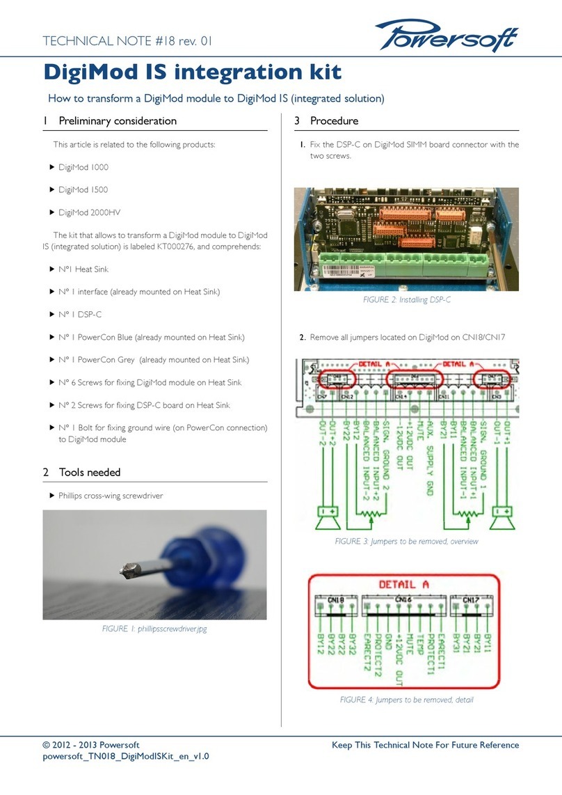
CONNECTION
VALVE MODE
STAT US
WiFi
Home
Away
Touch for Bypass
Hold for Water Shuto
Smarter Water Control™
flologic.com/connect
®
FloLogic CONNECT
Quick Start User Guide

FloLogic CONNECT
QQuick Start User Guide
This guide reviews the basics of operating your FloLogic System through the
FloLogic app. It also provides initial CONNECT Module and app setup instructions.
Visit the Support section of www.flologic.com to find any updates, helpful how-to
videos and to get answers to specific questions about operation and setup.
Scan for FloLogic App Overview Video
Scan for Connect Module Setup Video

TABLE OF CONTENTS
FloLogic CONNECT Setup
Creating an Account .............................................................................................. 1
Configuring the CONNECT Module.................................................................... 3
CONNECT Module Operation...............................................................................9
FloLogic App Basic Operation
System Mode......................................................................................................... 10
Settings.................................................................................................................. 12
Share a Device...................................................................................................... 15
Troubleshooting.................................................................................................... 16

1
CREATING AN ACCOUNT
FloLogic CONNECT Setup
CREATING AN ACCOUNT
1. Download the FloLogic app from the Apple or Google app stores.
2. From the home screen, touch the “Create Account” button in the lower left
corner.
3. Enter the email to associate with your account, the name to associate with you
as a user, and a password (Minimum 8 characters with upper case and lower
case letters, number(s) and one or more special characters).
4. You must receive and accept a confirmation email to activate the new account.
This may take several minutes. Check your spam folder if you don't see it.
5. Once you have set up an account, you can then log in to add a new device, or
accept an invitation to access an existing System.

2
FloLogic CONNECT Setup for App-Based Control
CREATING AN ACCOUNT
1. Download the FloLogic app from the Apple or Google app stores.
2. From the home screen, touch the “Create Account” button in the lower left
corner.
3. Enter the email to associate with your account, the name to associate with you
as a user, and a password.
4. You must receive and accept a confirmation email to activate the new account.
This may take several minutes.
5. Once you have set up an account, you can add a new device, or accept an
invitation to access an existing System.
CREATING AN ACCOUNT

3
CONFIGURING THE CONNECT MODULE
CONFIGURING THE CONNECT MODULE
1. Ensure that the Module mounting location is in an area with a strong 2.4 Ghz
WiFi signal. For an existing FloLogic setup, remove the Communication Cable
from the back of the FloLogic Control Panel; on a new setup, use the
Communication Cable from the FloLogic Valve.
2. Plug the black Communication Cable into the bottom of the Connect Module in
the right-side port, as you’re looking at the front of the Connect Module.
3. Then use the supplied white Local Connection Cable to plug into the left-hand
port of the Connect Module, plugging the other end into the existing Control
Panel. Cutting out the removable tab (depicted on the next page) on the
Control Panel may make this connection easier.
Extensions and longer lengths of the Communication Cable from the Valve are
available if required. Any standard telephone line cord can be used for the Local
Connection Cable, provided it is 4-conductor or greater and has “reversed”
plugs.

4
Local
Connection Cable
Communication
Cable from Valve
Removable Cable
Cutout
Factory Reset
Button
CONFIGURING THE CONNECT MODULE

5
Once the account has been setup,
the email verified and the cables
connected, log into the app. Stand
within 8 feet of the CONNECT
Module. Next, tap the “Add Device”
icon or tap the “+” symbol from the
dashboard screen to add an
additional device.
Please note, the FloLogic
CONNECT Module requires a
strong 2.4GHz router signal.
Network security experts
recommend that IoT devices get
provisioned to a guest Wi-Fi
network to segregate them from
other devices on the network.
CONFIGURING THE CONNECT MODULE

6
Enter the last six digits of the serial number found
printed on the bottom edge of the CONNECT WiFi
Module. If prompted, allow your device to join the
"FloLogic" network. Select your preferred WiFi
network from the provided list then enter the
password for the network (passwords are case
sensitive).
The CONNECT Module will now complete its
connection. This will take several minutes. When the
"CONNECTION" light on the CONNECT WiFi Module
turns solid green, you have successfully provisioned
the device. If the app does not immediately recognize
the device is online, you can close the app and
reopen it where will show as online.
If the device fails to connect after waiting five minutes,
see the next page for additional instructions.
CONFIGURING THE CONNECT MODULE

After five minutes, if you don’t get a green
CONNECTION light, you may have entered an
incorrect password. Press the WiFi button on the top
right of the Module and wait for the CONNECTION
light to blink red, close the app, reopen then restart
the process.
If the device fails to connect through the primary
method, you may be prompted to connect through a
"Legacy" method. Follow the prompts to open your
WiFi settings, connect to the FloLogic WiFi signal,
then return to the app to configure to the WiFi
network. Alternately the "Manual" method will ask for
the serial number on the CONNECT Module and
allow you to manually enter the SSID of the WiFi
network along with the password.
CONFIGURING THE CONNECT MODULE
7

8
After you get connected, personalize your System by
naming it and adding an installation address. The
Global Name field is the name that everyone
connected to your valve will see while the Friendly
Name allows you to name it something meaningful to
just yourself. IMPORTANT: Adding your insurance
information and address could help you qualify for
lower premium rates ongoing.
Once connected you can also access your FloLogic
device(s) from a browser by logging in at
myflologic.com and using the same login as the app.
Tap the "back" arrow to get to the app's main
screen and go to the Account page to enter your
phone number for future access to text alerts and
account prompts.
CONFIGURING THE CONNECT MODULE

9
CONNECT MODULE NOTIFICATIONS AND OPERATION
The CONNECT Module offers basic operation functions through its button
interface. See the below diagram to learn the functionality of each button
and about what the differing lights indicate.
CONNECTION
VALVE MODE
STATUS
WiFi
Home
Away
Touch for Bypass
Hold for Water Shutoff
Smarter Water Control™
flologic.com/connect
®
Touch to change router credentials. Hold five
seconds to restart provisioning process from the
beginning.
Places System in Home mode. Home mode
also turns water back on after a shutoff.
Places System in Away mode.
Touching puts System in Bypass mode.
Holding closes the valve for a water shutoff.
CONNECTION:
Flashing RED – Ready to Provision
Solid RED – Connecting to WiFi
Solid WHITE – Connecting to Internet
Solid BLUE – Connecting to Cloud Services
Solid GREEN – Connected and Online
VALVE MODE:
Solid GREEN – Home Mode
Solid YELLOW – Away Mode
Solid RED – Valve Closed
Flashing GREEN –Bypass Mode /
Return to Home
Flashing YELLOW – Bypass Mode /
Return to Away
STATUS:
GREEN – All OK
YELLOW – Attention Required
CONNECT MODULE OPERATION

10
APP OPERATION
FloLogic App Basic Operation:
Please note that FloLogic Systems with the CONNECT Module must continue to
have the local Control Panel powered up and operating. The Control Panel
enables local operation independent of an internet connection. When a
CONNECT Module is installed, the Control Panel will automatically remain in sync
with operation from the app, and vice versa.
HOW IT WORKS
FloLogic works by monitoring every water flow event that occurs at or above the
flow sensitivity setting. Normal water use comes in episodes whereas leaks are
continuous. FloLogic flags potential leaks when the Home or Away flow time is
exceeded.
SYSTEM MODE
To change the System mode, while on the Valve Status screen touch the mode
icon in the center of the screen to bring up the Mode Menu.

11
APP OPERATION
*MODES ARE AS FOLLOWS:
HOME MODE: Allows flow times that you can set so FloLogic won’t interfere with
showers and normal use, but will still flag and stop leaks. All flow time
allowances are adjustable.
AWAY MODE: Allows shorter flow times for ice makers, etc. to operate, while
flagging leaks quickly. Flow time allowances are adjustable, or the System can
shut off the water automatically in Away mode (when the Away time is set to
zero). Note that the ball valve auto exercises upon entering Away mode.
BYPASS: Ignores all flow for a set period of time. System automatically reverts
to Home or Away (per previous mode) upon expiration of the Bypass period.
SHUTOFF: Turns water off.
*See settings information on next page for more on System modes.

12
SETTINGS
To view and adjust
System settings, touch
the gear icon in the upper
right corner of the Valve
Status screen.
Adjustments to various
parameters can be made
within each setting
screen.
APP OPERATION

13
APP OPERATION
SYSTEM INFO: Lets you view or change Global or Friendly names for a System,
enter or edit the property address, add insurance policy information, update
software, manage the WiFi network connection, allows System disabling and
allows you to disown a System from your app/account.
FLOW SENSITIVITY: Also called the “Drip Rate,” on the Control Panel, sets the
flow level that must be reached in order for the System to begin monitoring flow.
Flow rates below this setting are ignored. FloLogic’s EverWatchTM detection
technology constantly monitors for leaks that flow at or above this setting. Flow
Sensitivity is adjustable between 0.5 - 48 ounces-per-minute.
HOME/AWAY: Allows adjusting the flow time allowances in Home and Away
modes. The Delay Away feature holds FloLogic in the Home mode for a period
upon Away mode activation. The Auto Away feature automatically activates Away
mode after no flow is recognized for the Auto Away time period.
BYPASS: Adjusts the Bypass mode time, for ignoring flow for set time periods.
TEMPERATURE: Activates low temp alert and low temp auto shutoff thresholds,
as well as allows thermometer calibration.

14
NOTIFICATIONS: Configures the System alerts and mode changes for which
you will receive notifications on your smartphone or tablet. Notification history is
also available here. Pre-Alert Notices give advance shutoff alerts, while No Flow
Detected alerts are sent when no water flow is detected for the interval of time
selected. This may be useful to monitor the use of water as a wellness check.
Note that you may also need to turn on notifications for the FloLogic app in your
phone's general settings in order to receive FloLogic push notifications.
ALERTS: Catalogs System alerts with date and timestamps.
COMMANDS LOG: Provides a history of commands received by the System.
PEOPLE: Lists all users for the respective System and allows Owners to invite
new users to have access to that System.
*Please note that some features of the app may still be in development and
therefore may not yet be available.
APP OPERATION

15
APP OPERATION
SHARE A DEVICE
From the Dashboard View, touch the Sharing
icon at the top. Touch Get Started and select the
System you wish to share, then the user
permissions you wish to grant. Next, enter the
email address of the individual. An email will be
sent to the individual providing instructions.
If the new user already has the app and an
account that matches the email address you
entered, they will see the invitation to access
your device. If they don’t have an account, they’ll
still see the invitation once they set up an
account, as long as their account email matches
your invitation email.

TROUBLESHOOTING
16
TROUBLESHOOTING:
Device Failed to Provision: This is likely due to an incorrect password or WiFi
misalignment. You will need to re-provision. Press the WiFi button on the side of the
CONNECT Module once. When CONNECTION slowly flashes red, you can restart the
provisioning process on page 5. A weak WiFi signal may cause a device to fail to
connect. A WiFi extender or signal booster may be required in this case.
Device Was On line But Remains Off line: This is likely due to a WiFi service issue
or weak WiFi signal. Check the WiFi signal and if necessary add a booster. Power
cycle by disconnecting the black cable then reconnecting. If device does not go
back online, press the WiFi button on the side of the CONNECT Module for five
seconds. When the CONNECTION light blinks red, then reconnect the device per
the provisioning instructions on page 5.
New Router/WiFi Password Change: Pressing the WiFi button quickly then re-
provisioning (per page 5 instructions) will allow you to connect a previously
provisioned device to a new router, or to an existing router with a new password.

FCC Statements
FCC Class B Part 15
This device complies with part 15 of the FCC Rules. Operation is subject to the following two
conditions: (1) This device may not cause harmful interference, and (2) This device must
accept any interference received, including interference that may cause undesired operation.
FCC ID: 2AZU8-CONNECTV2
To satisfy RF exposure requirements, this device and its antenna must operate with a
separation distance of at least 20 cm from all persons.
Changes or modifications not expressly approved by the party responsible for compliance
could void the user's authority to operate the equipment.
Table of contents
Popular Control Unit manuals by other brands

Honeywell
Honeywell DirectLine DL421 user manual
Cameron
Cameron WHEATLEY 820 Series Installation, operation and maintenance manual
Allen-Bradley
Allen-Bradley ControlNet 1747-ACN15 user manual
USR IOT
USR IOT USR-BLE100 user manual
Ricoh
Ricoh 411402 - EFI Fiery EB-105EX Controller printing guide
FISNAR
FISNAR F9000N Series manual
