manuals.online logo
Brands
  1. Home
  2. •
  3. Brands
  4. •
  5. Parker
  6. •
  7. Control Unit
  8. •
  9. Parker Sporlan LAC-4 Release note

Parker Sporlan LAC-4 Release note

INSTALLATION INSTRUCTIONS
To ensure proper performance, head
pressure control valves must be selected
and applied correctly. This is covered
thoroughly in Bulletin 90-30. However,
proper installation procedures are equally
important.
Valve Location/Piping Suggestions -
LAC-4 valves can be installed in horizontal
or vertical lines, whichever best suits the
application and permits easy accessibil-
ity of the valves. However, consideration
should be given to locating these valves
so they don’t act as oil traps or that solder
cannot run into the internal parts dur-
ing brazing. Care should also be taken
to install the valves with the flow in the
proper direction.
Figure 3 is a piping schematic only to illus-
trate the general location of the LAC-4
valve. In most cases the valve is located at
the condensing unit. When the condenser
is remote from the compressor, the usual
location is near the compressor. Spor-
lan recommends that recognized piping
references be consulted for assistance in
piping procedures. Sporlan is not respon-
sible for system design, any damage aris-
ing from faulty system design, or for mis-
application of its products. If these valves
are applied in any manner other than as
described in this bulletin, the Sporlan
warranty is void.
Inlet Strainer - The need for an inlet
strainer is a function of system cleanliness.
Inlet strainers are available for the LAC-4
and LAC-4-DS (3/8” ODF fittings must
have a rolled stop to support the strainer).
Keep in mind that the LAC model actu-
ally has two inlet fittings (condenser and
Head Pressure Control Valves
LAC-4 and LAC-4-DS
INSTALLATION AND SERVICING INSTRUCTIONS
SD-134 / 82021
discharge) and it may be desirable to use
an inlet strainer in both fittings.
Brazing Procedures - Any of the com-
monly used brazing alloys for high side
usage are satisfactory. However, when sol-
dering or brazing, it is very important that
the internal parts be protected by wrap-
ping the valve with a wet cloth to keep the
body temperature below 250°F. Also, when
using high temperature solders, the torch
tip should be large enough to avoid pro-
longed heating of the copper connections.
And, always direct the flame away from the
valve body.
Test and Operating Pressures - Inert
dry gases such as nitrogen, CO2or helium
are often used for leak detection. Excessive
leak testing or operating pressures may
damage these valves or reduce the life of
the diaphragm or bellows.
CAUTION: Inert gases must be added
to the system carefully through a
pressure regulator. Unregulated gas
pressure can seriously damage the
system and endanger human life.
Never use oxygen or explosive gases.
The maximum pressure that this valve
can withstand without damage is 500 psig.
Care must be taken to keep test or operat-
ing pressures below this maximum rated
pressure.
Table 1
FITTING SIZE INLET STRAINER
PART NUMBER
3/8” 825-003
1/2” 825-004
RECEIVER
DISCHARGE
DISCHARGE
RECEIVER
CONDENSER
Page 2 / SD-134
VALVE SETTINGS
LAC-4
The LAC-4 is available with 4 standard set-
tings for various refrigerants as shown in
Table 2. Some manufacturers’ systems use
other settings which are critical to system
operation e.g. harvest cycle on ice makers.
These non-standard settings are available
for replacement but delivery time may be
extended. See Figure 1.
LAC-4-DS
The LAC-4-DS provides the choice of two
settings, 100 psig or 180 psig (other com-
binations of high and low settings have
been produced). The higher setting is ob-
tained by a combination spring force and
air charge in the upper dome assembly.
See Figure 2. The valve supplied with the
higher of the two settings is stamped on
the hex flats of the condenser connection.
When the valve is used on systems with:
Refrigerant 407A, 407F, 448A, 449A,
and 502
1. Remove low setting stamp from hex flat
with a file.
2. Install valve. It is set to maintain 180
psig during low ambient conditions.
Refrigerant 134a and 513A
1. Clip 3/4” off dome capillary tube to
relieve air charge.
2. Remove paint from end of
capillary tube.
3. Fuse tip to prevent moisture from
entering dome.
4. Remove high setting stamp from hex
flat with a file.
5. Install valve. It is now set to maintain
100 psig during low ambient
conditions.
CONDENSER
LAC - 4
Figure 1
LAC - 4 - DS
Figure 2
WARNING: Serious injury could result from an explosion caused by the rapid expansion
of trapped liquid refrigerant subjected to high temperature. Always open or vent the sys-
tem before applying heat to remove system components. Break the element charging
cap tube on valve dome by hand or with a clean cut tool. Do not use side cutters which may
seal the opening.
SERVICE INSTRUCTIONS
There are several possible causes for system malfunction with “refrigerant side” head
pressure control and these may be difficult to isolate from each other. As with any form
of system trouble-shooting, it is necessary to know the existing operating temperatures
and pressures before system problems can be determined. Once the actual malfunction
is established, it is easier to pinpoint the cause and then take suitable corrective action.
The following chart lists the most common malfunctions, the possible causes, and the
remedies.
Figure 3
The LAC-4 Liquid Flow capacities are equal to the above hot gas flow capacities (at 5 psi ∆P) at less than
two psi pressure drop.
Table 2
REFRIGERANT RECOMMENDED SETTINGS (PSI)
12, 134a, 513A 100
401A 120
22, 502, 407A, 407F, 448A, 449A 180
404A, 507, 402A 210
Table 3
LOW AMBIENT (Winter) CAPACITIES - TONS
Capacities are based on 0°F Evaporator, 94°F Condenser, 10°F Subcooled Liquid;
Valve Setting of 100 psig for R-134a / 513A;
180 psig for 407A / 407F / 448A / 449A; 210 psig for 404A / 507
PRESSURE
DROP ACROSS
VALVE
(PSI)
REFRIGERANT
134a / 513A 448A / 449A 407A / 407F 404A / 507
MINIMUM AMBIENT DESIGN TEMPERATURE °F
-20 0 20 -20 0 20 -20 0 20 -20 0 20
5 2.9 3.1 3.5 3.4 3.6 3.9 3.7 4.0 4.3 2.5 2.6 2.9
10 4.0 4.3 4.8 4.7 5.0 5.5 5.2 5.6 6.1 3.5 3.7 4.0
20 5.4 5.9 6.6 6.5 7.0 7.6 7.2 7.7 8.4 4.8 5.1 4.9
SD-134 / Page 3
COMPRESSOR RECEIVER
CONDENSER
LAC
FOR USE ON REFRIGERATION and/or AIR CONDITIONING SYSTEMS ONLY
⚠WARNING – USER RESPONSIBILITY
Failure or improper selection or improper use of the products described herein or related items can
cause death, personal injury and property damage.
• This document and other information from Parker-Hannifin Corporation, its subsidiaries and authorized distributors provide
product or system options for further investigation by users having technical expertise.
• The user, through its own analysis and testing, is solely responsible for making the final selection of the system and
components and assuring that all performance, endurance, maintenance, safety and warning requirements of the
application are met. The user must analyze all aspects of the application, follow applicable industry standards, and follow
the information concerning the product in the current product catalog and in any other materials provided from Parker or
its subsidiaries or authorized distributors.
• To the extent that Parker or its subsidiaries or authorized distributors provide component or system options based upon
data or specifications provided by the user, the user is responsible for determining that such data and specifications are
suitable and sufficient for all applications and reasonably foreseeable uses of the components or systems.
SD-134 / 82021
© 2021 Parker Hannin Corporation
Parker Hannin Corporation
Sporlan Division
206 Lange Drive • Washington, MO 63090 USA
phone 636 239 1111 • fax 636 239 9130
www.sporlan.com
MALFUNCTION - LOW HEAD PRESSURE
POSSIBLE CAUSE REMEDY
1. Insufficient refrigerant charge to
adequately flood condenser
2. LAC fails to close due to:
a. Foreign material in valve.
b. Loss of air charge in element.
3. Wrong setting on LAC (e.g. 100 psig
on Refrigerant 22 or 502 system)
4. Discharge line to LAC restricted.
1. Charge system according to
Manufacturers Specifications or if
unavailable use Bulletin 90-30-1.
2. See Below:
a. Cause LAC to open by raising
condensing/receiver pressure
above valve setting by cycling
condenser fan. If foreign material
does not pass through valve,
replace LAC.
b. Replace LAC.
3. Replace LAC with valve with correct
setting.
4. Remove restriction in fitting(s) or line.
MALFUNCTION - HIGH HEAD PRESSURE
POSSIBLE CAUSE REMEDY
1. Dirty condenser coil.
2. Air on condenser blocked off.
3. Too much refrigerant charge.
4. Undersized receiver.
5. Non-condensable (air) in system.
6. Liquid port or liquid line plugged.
7. Wrong setting on LAC (e.g. 180 psig
on Refrigerant 12 systems).
8. Spring overheated during
installation, increasing the LAC
setting.
9. Condenser fans not running.
1. Clean coil.
2. Clear area around unit.
3. Remove charge until proper head
pressure is maintained.
4. Check receiver capacity against
refrigerant required to maintain
desired head pressure.
5. Purge from system.
6. Remove blockage in port or liquid
line.
7. Replace LAC with valve with correct
setting.
8. Replace LAC.
9. Repair or replace fan motor.
Page 4 / SD-134

This manual suits for next models

1

Other Parker Control Unit manuals

Parker PQDXXA-Z10 Installation and operation manual

Parker

Parker PQDXXA-Z10 Installation and operation manual

Parker S8VS User manual

Parker

Parker S8VS User manual

Parker P33 Quick setup guide

Parker

Parker P33 Quick setup guide

Parker Series DFplus User manual

Parker

Parker Series DFplus User manual

Parker PK2 User manual

Parker

Parker PK2 User manual

Parker PSSNACM12A Installation and maintenance instructions

Parker

Parker PSSNACM12A Installation and maintenance instructions

Parker 221 Series User manual

Parker

Parker 221 Series User manual

Parker 8902/LS User manual

Parker

Parker 8902/LS User manual

Parker Vansco User manual

Parker

Parker Vansco User manual

Parker U Series Technical specifications

Parker

Parker U Series Technical specifications

Parker 810 Series Assembly instructions
Parker

Parker 810 Series Assembly instructions

Parker B5 User manual

Parker

Parker B5 User manual

Parker DP-V1 User manual

Parker

Parker DP-V1 User manual

Parker ASV5000 Series User manual

Parker

Parker ASV5000 Series User manual

Parker DxFB Series User manual

Parker

Parker DxFB Series User manual

Parker D*1VW*EE Series User manual

Parker

Parker D*1VW*EE Series User manual

Parker D1FV EE Series User manual

Parker

Parker D1FV EE Series User manual
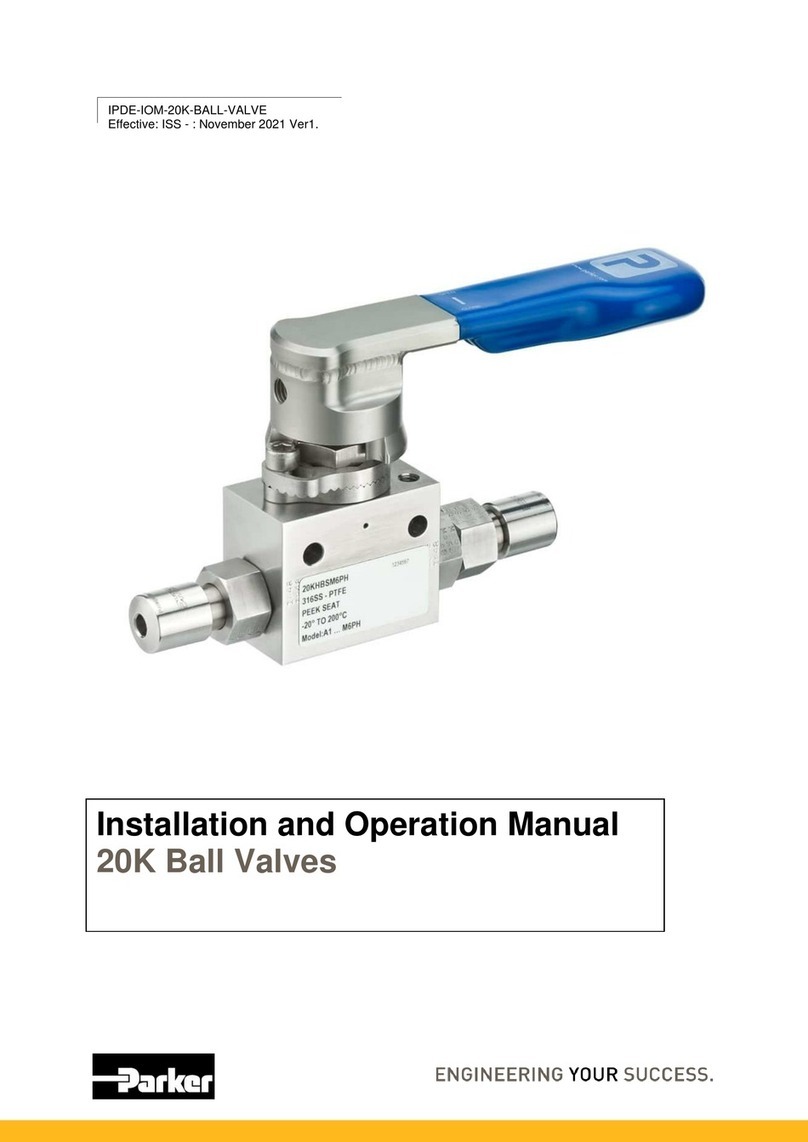
Parker CK4A-DN Operating and installation instructions

Parker

Parker CK4A-DN Operating and installation instructions

Parker CK-1 Guide

Parker

Parker CK-1 Guide

Parker HASV08R User manual

Parker

Parker HASV08R User manual

Parker CW Series Operating instructions

Parker

Parker CW Series Operating instructions

Parker C6 Series Installation and maintenance instructions

Parker

Parker C6 Series Installation and maintenance instructions

Parker CK-6D User manual

Parker

Parker CK-6D User manual

Parker D31DW*EE Series User manual

Parker

Parker D31DW*EE Series User manual
Popular Control Unit manuals by other brands

Hi-Link HLK-RM08S user manual

Hi-Link

Hi-Link HLK-RM08S user manual

urmet domus 1051/020 quick start guide

urmet domus

urmet domus 1051/020 quick start guide

LEGRAND Bticino H4652 manual

LEGRAND

LEGRAND Bticino H4652 manual

Vortice VORT T Instruction booklet

Vortice

Vortice VORT T Instruction booklet

Circutor line-M-4IO-R instruction manual

Circutor

Circutor line-M-4IO-R instruction manual

Giant Alarm System 3010-1A user manual

Giant Alarm System

Giant Alarm System 3010-1A user manual

Trenz Electronic TE0808 Schematics

Trenz Electronic

Trenz Electronic TE0808 Schematics

Sine Systems ACU-1 Setting up

Sine Systems

Sine Systems ACU-1 Setting up

Ring Engineering AM-1b user manual

Ring Engineering

Ring Engineering AM-1b user manual

Salcom 12-32-0000 product manual

Salcom

Salcom 12-32-0000 product manual

MEDENUS S 100 Operating and maintenance instructions

MEDENUS

MEDENUS S 100 Operating and maintenance instructions

Endress E-RMA LAN Translation of the original operating manual

Endress

Endress E-RMA LAN Translation of the original operating manual

Allen-Bradley PowerFlex 755 user manual

Allen-Bradley

Allen-Bradley PowerFlex 755 user manual

Fermax 2911 manual

Fermax

Fermax 2911 manual

Monacor DMP-100R quick guide

Monacor

Monacor DMP-100R quick guide

Ebyte E107-SC01 Series user manual

Ebyte

Ebyte E107-SC01 Series user manual

Cornelius LEOPARD ERV Operator's manual

Cornelius

Cornelius LEOPARD ERV Operator's manual

National Instruments NI 9759 user manual

National Instruments

National Instruments NI 9759 user manual

manuals.online logo
manuals.online logoBrands
  • About & Mission
  • Contact us
  • Privacy Policy
  • Terms and Conditions

Copyright 2025 Manuals.Online. All Rights Reserved.