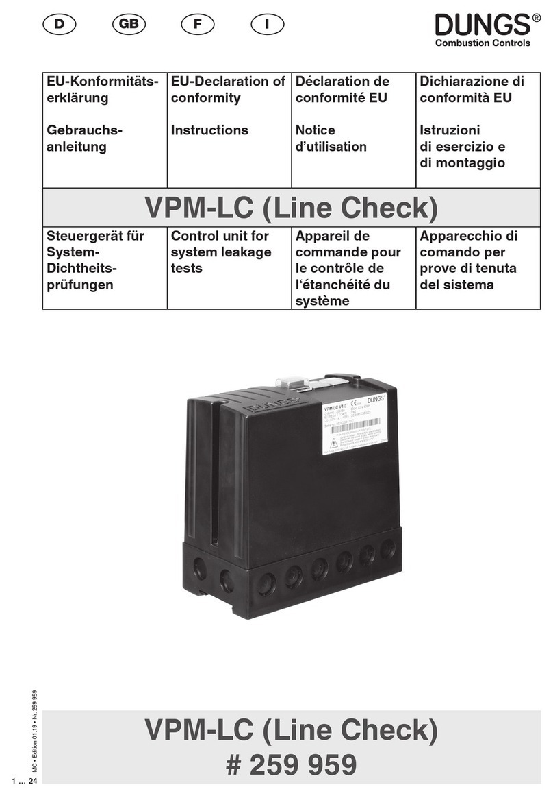
Dungs VPM-VC User manual
Other Dungs Control Unit manuals
Dungs
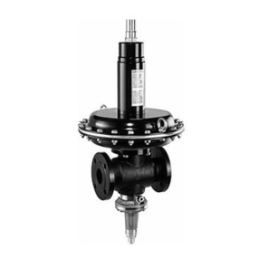
Dungs FRM 100025 User manual
Dungs
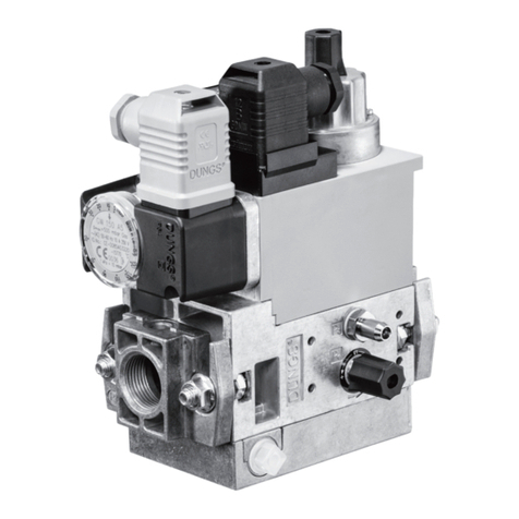
Dungs GasMultiBloc MB-D B07 Series User manual
Dungs
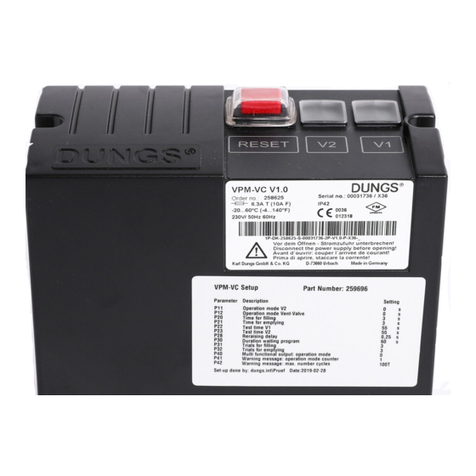
Dungs VPM-VC Service manual

Dungs
Dungs DMV 11 eco Series Service manual
Dungs
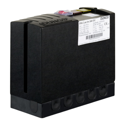
Dungs DSLC px Vx Service manual
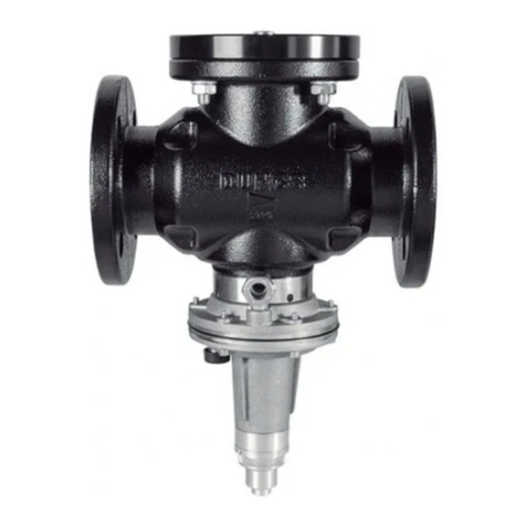
Dungs
Dungs SAV 100065 MD User manual
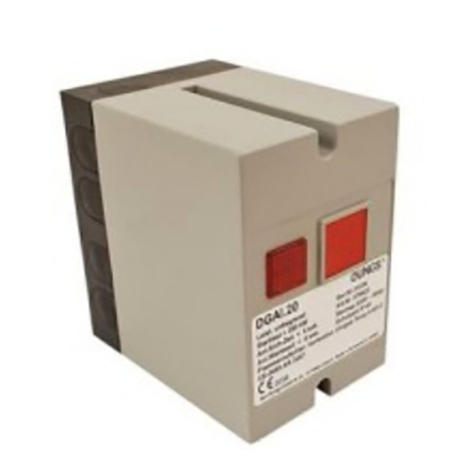
Dungs
Dungs DGAI. 20/5 Product guide
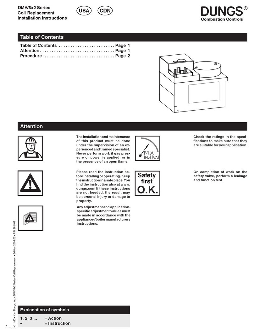
Dungs
Dungs DMV Series User manual

Dungs
Dungs MV X Product guide
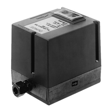
Dungs
Dungs VDK 200 Service manual
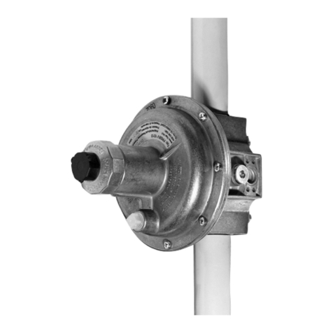
Dungs
Dungs FRSBV User manual

Dungs
Dungs VPM-VC User manual
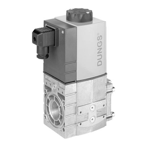
Dungs
Dungs SV-DLE 1005/604 Service manual
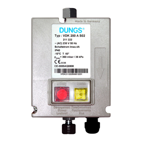
Dungs
Dungs VDK 200 A S02 Service manual
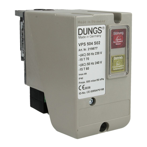
Dungs
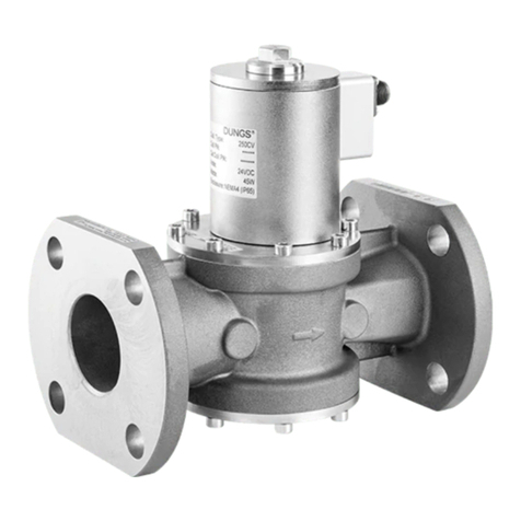
Dungs VPS 504 Service manual
Dungs
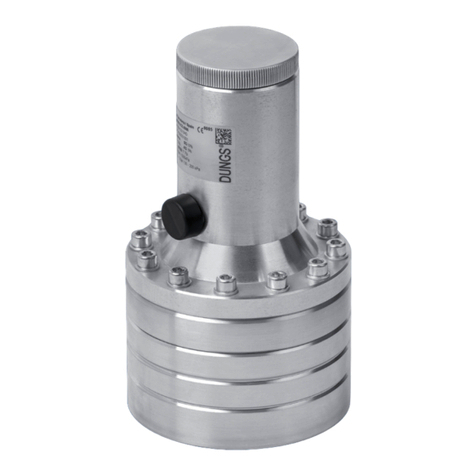
Dungs HPSV 10020/604 User manual
Dungs
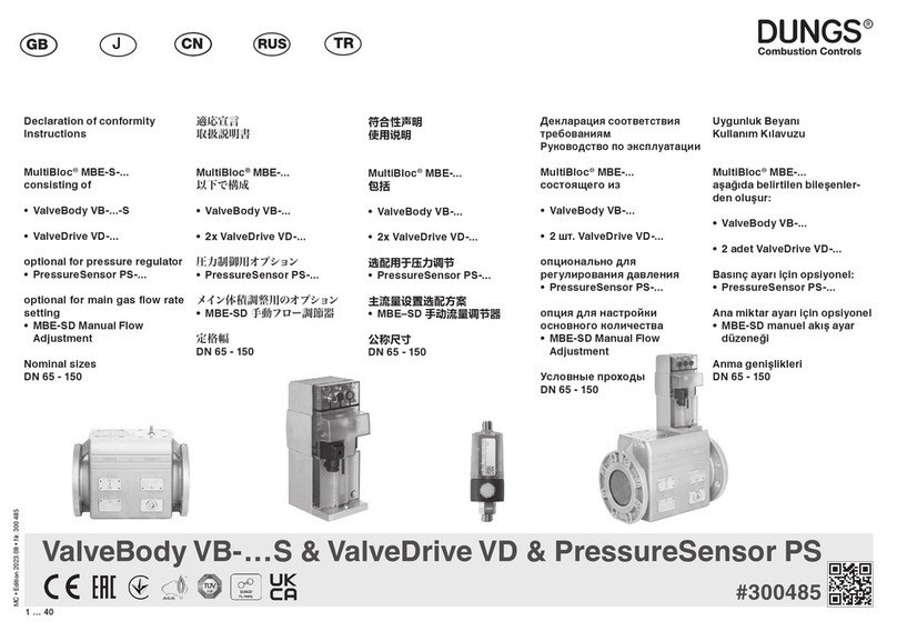
Dungs FRSBV 20010 Series User manual
Dungs
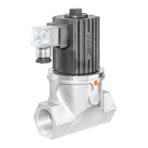
Dungs MultiBloc MBE-S Series User manual
Dungs
Dungs GSV Series User manual
Dungs
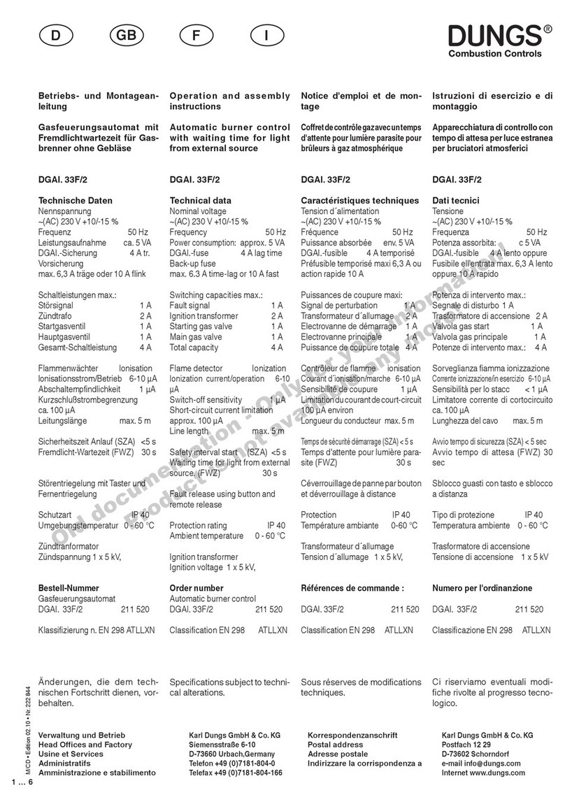
Dungs DGAI. 33F/2 Service manual
Popular Control Unit manuals by other brands

Festo
Festo Compact Performance CP-FB6-E Brief description

Elo TouchSystems
Elo TouchSystems DMS-SA19P-EXTME Quick installation guide

JS Automation
JS Automation MPC3034A user manual

JAUDT
JAUDT SW GII 6406 Series Translation of the original operating instructions

Spektrum
Spektrum Air Module System manual

BOC Edwards
BOC Edwards Q Series instruction manual

KHADAS
KHADAS BT Magic quick start

Etherma
Etherma eNEXHO-IL Assembly and operating instructions

PMFoundations
PMFoundations Attenuverter Assembly guide

GEA
GEA VARIVENT Operating instruction

Walther Systemtechnik
Walther Systemtechnik VMS-05 Assembly instructions

Altronix
Altronix LINQ8PD Installation and programming manual
