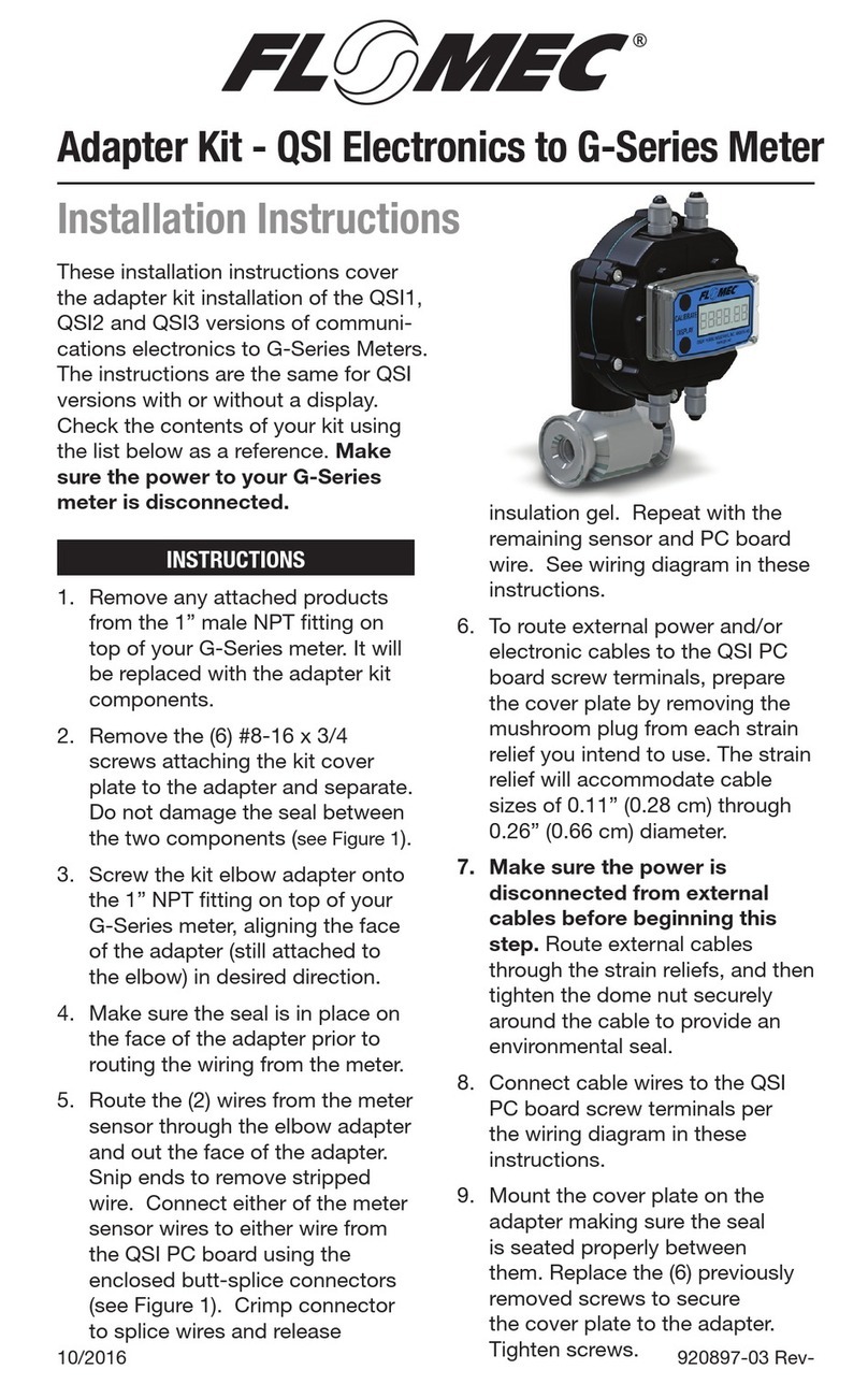
Flomec QSI Series User manual

920897-01 Rev-10/2016
Adapter Kit - QSI Electronics to OM Meter
Installation Instructions
INSTRUCTIONS
1. Remove the circular plate (or
other product) from the top
of your OM meter. It will be
replaced with the adapter kit
components.
2. Remove the (6) #8-16 x 3/4
screws attaching the kit cover
plate to the adapter and separate.
Do not damage the seal between
the two components (see Figure
2).
3. Install the O-ring received with
the kit in the O-ring gland on the
bottom of the adapter; mount
the adapter to the OM meter and
secure with (4) metric screws
provided with the kit. Tighten
screws.
4. Make sure the seal is in place on
top of the adapter prior to routing
the wiring from the meter.
5. Route the wiring from the meter
up through the adapter and
connect the wires to the QSI
PC board screw connectors,
per the wiring diagram in these
instructions.
6. To route external power and/or
electronic cables to the QSI PC
board screw connectors, prepare
the cover plate by removing the
mushroom plug from each strain
relief you intend to use. The strain
relief will accommodate cable
sizes of 0.11” (0.28 cm) through
0.26” (0.66 cm) diameter.
7. Make sure the power is
disconnected from external
cables before beginning this step.
Route external cables through the
strain relief(s), and then tighten
the dome nut securely around the
cable to provide an environmental
seal.
8. Connect cable wires to the QSI
PC board screw connectors
per the wiring diagram in these
instructions.
9. Mount the cover plate on the
adapter making sure the seal
is seated properly between
them. Replace the (6) previously
removed screws to secure the
cover plate to the adapter.
Tighten screws.
These installation instructions
cover the adapter kit installation of
the QSI1, QSI2 and QSI3 versions
of communications electronics to
OM Meters. The instructions are
the same for QSI versions with
or without a display. Check the
contents of your kit using the list
below as a reference. Make sure
the power to your OM meter is
disconnected.

2
O-RING
ADAPTER
SEAL
COVER PLATE
Q09 DISPLAY (SHOWN)
(OR)
NO DISIPLAY
(4) M5-0.8 X 12 SCREW
(6) SCREWS, #8-16 X 3/4
(4) MUSHROOM PLUGS
O-RING GLAND
Figure 1
KIT CONTENTS
• (1) Completely assembled QSI
module (with or without a display).
• (4) M5-0.8 x 12 metric screws.
• (1) O-ring.
• (1) Instruction sheet.
• (1) QSI Owner’s manual.
• (1) Q09 Owner’s manual (if kit
includes Q09 display).

3
TEMP SENSOR
PT100-Red Sensor VCC Output
PT100-White Input High Side
PT100-Blue Input Return
RS-485 (Galvanically Isolated)
RS485 (+) Positive Signal
RS485 (-) Negative Signal
RS485 GND Circuit Ground*
PULSE INPUT
+5V 5VDC output to pow-
er external sensor
(+)
Digital Pulse Fre-
quency Input, up to
3kHz
(-) Digital Pulse Return
4-20mA (Galvanically Isolated)
(+)
4 to 20mA current
loop - current in to
transmitter
(-)
4 to 20mA current
loop - current out of
transmitter*
Coil A Low level sine wave
input
Coil B Low level sine wave
input
GPI SENSOR
Ribbon cable connection to GPI
custom sensor designs
PULSE OUTPUT
(Galvanically Isolated)
(-) Pulse Output return
current*
(+)
Pulse Output fre-
quency output. This
is a “current sinking
open collector” out-
put.***
POWER INPUT
(-) 12-36V AC or DC
Input A**
(+) 12-36V AC or DC
Input B**
*NOTE: It is not recommended to
connect isolated ground connections
together or to board common.
**NOTE: Polarity of voltage for AC/
DC is not important. However an
earth ground isolated power supply is
required to prevent earth ground loop
currents and ground fault conditions.
***NOTE: This output may require an
external pull up resistor if interfacing
equipment does not include one.
PT100-Red
Coil A
GPI Sensor
Coil B
-
+
-
+
PT100-White Sensor #1
PT100-Blue
PT100-Red
PT100-White
PT100-Blue
RS-485 +
RS-485 -
RS-485 GND
+5v
+
-
+
-
Sensor #2
RS-485
Pulse Input
4-20mA
Pulse Output
Power
Figure 2
TERMINAL CONNECTIONS CHART

4
WIRING DIAGRAMS
QSI VERSION 1 PC BOARD
WIRING DIAGRAM
QSI Version 1
RS-485
BTU
Pulse Out
RTDs
RS-485
Pulse
Input Power In
Inputs: Temp Sensors, Pulse Input
Outputs: RS-485, Pulse Output
(+) (-)
Power (-)
Power (+)
ISOLATED
POWER
SUPPLY
12-36V AC/DC
Pulse Out (+)
Pulse Out (-)
Open Collector
Pulse Input
RS485 (-)
RS485 (GND)
R2 may be
required in some
installations.
Recommended
value=120Ω
Shield recommended. If used, connect
to Customer Equipment only.
*Shield
Customer
Equipment
Customer
Equipment
RS485 (+)
RS485 (-)
RS485 (GND)
RS485 (+)
PT100 (White)
PT100 (Blue)
PT100 (Red)
PT100 (White)
PT100 (Blue)
PT100 (Red)
R2
Pulse In (+)
Pulse In (-)
+5V
OM Meter
Electronics
Hall Effect, or
Reed Switch
R1
*NOTE: Regarding resistor “R1”: R1not generally required for distance up to 25 ft.
Use R1= 10k (10000 ohms) for distance up to 50 ft.
Use R1= 5.1k (5100 ohms) for distance up to 100 ft.
Use R1= 2.7k (2700 ohms) for distance up to 250 ft.
Do not use R1less than 2.4k (2400 ohms)
Figure 3
QSI VERSION 1 PC BOARD
WIRING DIAGRAM
QSI Version 1
RS-485
BTU
Pulse Out
RTDs
RS-485
Pulse
Input Power In
Inputs: Temp Sensors, Pulse Input
Outputs: RS-485, Pulse Output
(+) (-)
Power (-)
Power (+)
ISOLATED
POWER
SUPPLY
12-36V AC/DC
Pulse Out (+)
Pulse Out (-)
Open Collector
Pulse Input
RS485 (-)
RS485 (GND)
R2 may be
required in some
installations.
Recommended
value=120Ω
Shield recommended. If used, connect
to Customer Equipment only.
*Shield
Customer
Equipment
Customer
Equipment
RS485 (+)
RS485 (-)
RS485 (GND)
RS485 (+)
PT100 (White)
PT100 (Blue)
PT100 (Red)
PT100 (White)
PT100 (Blue)
PT100 (Red)
R2
Pulse In (+)
Pulse In (-)
+5V
OM Meter
Electronics
Hall Effect, or
Reed Switch
R1
*NOTE: Regarding resistor “R1”: R1not generally required for distance up to 25 ft.
Use R1= 10k (10000 ohms) for distance up to 50 ft.
Use R1= 5.1k (5100 ohms) for distance up to 100 ft.
Use R1= 2.7k (2700 ohms) for distance up to 250 ft.
Do not use R1less than 2.4k (2400 ohms)
Figure 4
See Figure 5
or Figure 6

5
WIRING DIAGRAMS
Figure 5
Connection / Wiring Diagram
Standard Pulse Output Board
+5V
OR
Pulse In -
QSI
Pulse
Input
Pull Up
Resistor
R1
Not Both
Pulse In +
Pulse In +
Pulse In -
Figure 6
Connection / Wiring Diagram
Reed Only Pulse Output Board
X
Pulse In +
Pulse In -
(Recommended, but not required)

6
QSI VERSION 2 PC BOARD
WIRING DIAGRAM
QSI Version 2
Pulse In
BTU
Pulse Out
RTDs
Pulse
Input Power In
Inputs: Temp Sensors, Pulse Input
Outputs: Pulse Output
(+) (-)
Power (-)
Power (+)
ISOLATED
POWER
SUPPLY
12-36V AC/DC
Pulse Out (+)
Pulse Out (-)
Open Collector
Pulse Input
Customer
Equipment
PT100 (White)
PT100 (Blue)
PT100 (Red)
PT100 (White)
PT100 (Blue)
PT100 (Red)
Pulse In (+)
Pulse In (-)
+5V
OM Meter
Electronics
Hall Effect, or
Reed Switch
R1
*NOTE: Regarding resistor “R1”: R1not generally required for distance up to 25 ft.
Use R1= 10k (10000 ohms) for distance up to 50 ft.
Use R1= 5.1k (5100 ohms) for distance up to 100 ft.
Use R1= 2.7k (2700 ohms) for distance up to 250 ft.
Do not use R1less than 2.4k (2400 ohms)
Figure 7
WIRING DIAGRAMS
QSI VERSION 2 PC BOARD
WIRING DIAGRAM
QSI Version 2
Pulse In
BTU
Pulse Out
RTDs
Pulse
Input Power In
Inputs: Temp Sensors, Pulse Input
Outputs: Pulse Output
(+) (-)
Power (-)
Power (+)
ISOLATED
POWER
SUPPLY
12-36V AC/DC
Pulse Out (+)
Pulse Out (-)
Open Collector
Pulse Input
Customer
Equipment
PT100 (White)
PT100 (Blue)
PT100 (Red)
PT100 (White)
PT100 (Blue)
PT100 (Red)
Pulse In (+)
Pulse In (-)
+5V
OM Meter
Electronics
Hall Effect, or
Reed Switch
R1
*NOTE: Regarding resistor “R1”: R1not generally required for distance up to 25 ft.
Use R1= 10k (10000 ohms) for distance up to 50 ft.
Use R1= 5.1k (5100 ohms) for distance up to 100 ft.
Use R1= 2.7k (2700 ohms) for distance up to 250 ft.
Do not use R1less than 2.4k (2400 ohms)
Figure 8
See Figure 5
or Figure 6

7
WIRING DIAGRAMS
QSI VERSION 3 PC BOARD
WIRING DIAGRAM
QSI Version 3
WIRING DIAGRAM
QSI Version 3
4-20mA
Pulse Out
4-20mA
Pulse
Input Power In
Inputs: OM or Conditioned Signal Sensor (Open Collector)
Outputs: Customer Equipment, 4-20mA Sensing, Built-in Loop Power Supply
(+) (-)
Power (-)
Power (+)
ISOLATED
POWER
SUPPLY
12-36V AC/DC Pulse Out (+)
Isolated Outputs
Customer Equipment with Built-in Power Supply
Inputs
Pulse Out (-)
Customer
Equipment
Open
Collector
4-20mA (+)
Min. V = 8.5
Max. V = 36
4-20mA (-)
Customer
Equipment
Customer Equipment without Built-in Power Supply
- 4-20mA Output with Separate Power Supply
(+) (-)
Power (-)
Power (+)
ISOLATED
POWER
SUPPLY
12-36V AC/DC
4-20mA (+)
4-20mA (-) (Current)
(Current)
(Current)
Loop (+)
Loop (-)
Customer
Equipment
Pulse In (+)
Pulse In (-)
+5V
Hall Effect, or
Reed Switch
OM Meter
Electronics
R1
- Digital Pulse Input
- 4-20mA and Pulse Outputs
*NOTE: Regarding resistor “R1”: R1not generally required for distance up to 25 ft.
Use R1= 10k (10000 ohms) for distance up to 50 ft.
Use R1= 5.1k (5100 ohms) for distance up to 100 ft.
Use R1= 2.7k (2700 ohms) for distance up to 250 ft.
Do not use R1less than 2.4k (2400 ohms)
Caution: When reassembling the
cover plate, make sure the
enclosure seal is not crimped or
twisted. Do not over-tighten
screws (hand-tighten only).
(+) (-)
Min. V = 8.5
Max. V = 36
Isolated
Power Supply
Figure 9
QSI VERSION 3 PC BOARD
WIRING DIAGRAM
QSI Version 3
WIRING DIAGRAM
QSI Version 3
4-20mA
Pulse Out
4-20mA
Pulse
Input Power In
Inputs: OM or Conditioned Signal Sensor (Open Collector)
Outputs: Customer Equipment, 4-20mA Sensing, Built-in Loop Power Supply
(+) (-)
Power (-)
Power (+)
ISOLATED
POWER
SUPPLY
12-36V AC/DC Pulse Out (+)
Isolated Outputs
Customer Equipment with Built-in Power Supply
Inputs
Pulse Out (-)
Customer
Equipment
Open
Collector
4-20mA (+)
Min. V = 8.5
Max. V = 36
4-20mA (-)
Customer
Equipment
Customer Equipment without Built-in Power Supply
- 4-20mA Output with Separate Power Supply
(+) (-)
Power (-)
Power (+)
ISOLATED
POWER
SUPPLY
12-36V AC/DC
4-20mA (+)
4-20mA (-) (Current)
(Current)
(Current)
Loop (+)
Loop (-)
Customer
Equipment
Pulse In (+)
Pulse In (-)
+5V
Hall Effect, or
Reed Switch
OM Meter
Electronics
R1
- Digital Pulse Input
- 4-20mA and Pulse Outputs
*NOTE: Regarding resistor “R1”: R1not generally required for distance up to 25 ft.
Use R1= 10k (10000 ohms) for distance up to 50 ft.
Use R1= 5.1k (5100 ohms) for distance up to 100 ft.
Use R1= 2.7k (2700 ohms) for distance up to 250 ft.
Do not use R1less than 2.4k (2400 ohms)
Caution: When reassembling the
cover plate, make sure the
enclosure seal is not crimped or
twisted. Do not over-tighten
screws (hand-tighten only).
(+) (-)
Min. V = 8.5
Max. V = 36
Isolated
Power Supply
Figure 10
See Figure 5
or Figure 6

920897-01 Rev-10/2016
QSI VERSION 3 PC BOARD
WIRING DIAGRAM
QSI Version 3
WIRING DIAGRAM
QSI Version 3
4-20mA
Pulse Out
4-20mA
Pulse
Input Power In
Inputs: OM or Conditioned Signal Sensor (Open Collector)
Outputs: Customer Equipment, 4-20mA Sensing, Built-in Loop Power Supply
(+) (-)
Power (-)
Power (+)
ISOLATED
POWER
SUPPLY
12-36V AC/DC Pulse Out (+)
Isolated Outputs
Customer Equipment with Built-in Power Supply
Inputs
Pulse Out (-)
Customer
Equipment
Open
Collector
4-20mA (+)
Min. V = 8.5
Max. V = 36
4-20mA (-)
Customer
Equipment
Customer Equipment without Built-in Power Supply
- 4-20mA Output with Separate Power Supply
(+) (-)
Power (-)
Power (+)
ISOLATED
POWER
SUPPLY
12-36V AC/DC
4-20mA (+)
4-20mA (-) (Current)
(Current)
(Current)
Loop (+)
Loop (-)
Customer
Equipment
Pulse In (+)
Pulse In (-)
+5V
Hall Effect, or
Reed Switch
OM Meter
Electronics
R1
- Digital Pulse Input
- 4-20mA and Pulse Outputs
*NOTE: Regarding resistor “R1”: R1not generally required for distance up to 25 ft.
Use R1= 10k (10000 ohms) for distance up to 50 ft.
Use R1= 5.1k (5100 ohms) for distance up to 100 ft.
Use R1= 2.7k (2700 ohms) for distance up to 250 ft.
Do not use R1less than 2.4k (2400 ohms)
Caution: When reassembling the
cover plate, make sure the
enclosure seal is not crimped or
twisted. Do not over-tighten
screws (hand-tighten only).
(+) (-)
Min. V = 8.5
Max. V = 36
Isolated
Power Supply
Figure 11
WIRING DIAGRAMS
© 2016 Great Plains Industries, Inc., All Rights Reserved.
Great Plains Industries, Inc. / 888-996-3837 / GPI.net
Other manuals for QSI Series
2
This manual suits for next models
3
Table of contents
Other Flomec Adapter manuals
Popular Adapter manuals by other brands
Sony
Sony MSACEX1 - Adaptateur Memory Stick Duo Express... operating instructions
NETGEAR
NETGEAR XAV1301v1/XAVB1301v1 asennusopas
CNET
CNET CWC-854 Product specifications
Cisco
Cisco Linksys PCM1000 Quick installation
AUDAC
AUDAC MBK260 installation manual
Panasonic
Panasonic CF-AA1653A2 operating instructions

ZyXEL Communications
ZyXEL Communications NWD210N user guide
Dragino
Dragino LA66 user manual
Airlink101
Airlink101 AWLC3026T Quick installation guide
Texas Instruments
Texas Instruments Serial Programming Adapter MSP430 user guide

Exibel
Exibel ADD009 quick start guide
oticon
oticon FittingLINK 3.0 Instructions for use
