Flonidan Uniflo 1200 GVEC User manual

Uniflo 1200 GVEC
Accessories
Pulse divider option board
Product number : 0618615-000
Manual
M/06180XX/46
Rev. 28.11.05
Please look at our homepage www.flonidan.dk that you have the newest version of the document.

U:\Hovedbibliotek\Produkter\Standard\Uniflo 1200\2. Kundemappe UK\5_Option board_Pulse in\5.3_Pulse_divider_card\Pulse divider
Board.doc
Page 2 of 6
PULSE DIVIDER
CONTENT
1.0 Introduction..................................................................................................................3
2.0 Mounting.......................................................................................................................3
3.0 Functionality ................................................................................................................4
3.1 General ..................................................................................................................................................4
3.2 Power fail ...............................................................................................................................................5
3.3 Max input frequency...............................................................................................................................5
3.4 Diode LED's ...........................................................................................................................................5
5.0 Technical data..............................................................................................................5
5.1 Dimensions ............................................................................................................................................5
5.2 Common specifications ..........................................................................................................................6
5.3 Markings.................................................................................................................................................6

U:\Hovedbibliotek\Produkter\Standard\Uniflo 1200\2. Kundemappe UK\5_Option board_Pulse in\5.3_Pulse_divider_card\Pulse divider
Board.doc
Page 3 of 6
PULSE DIVIDER
1.0 Introduction
The Pulse divider is an option board, which makes it possible to receive inputs pulses from various meter
types and repeat them either 1 to 1, or divided by 10, 100, 1000 or 10000.
The Pulse divider option board may be used for receiving pulses in the range 0-5 kHz depending on the
pulse input type.
The output is galvanic isolated from the input and the Uniflo 1200.
Definitions
Technicians are qualified persons educated or trained to mount, operate, and also troubleshoot technically
correct and in accordance with safety regulations.
Limitations
This manual only applies to the following Product numbers:
0618615-000 Uniflo 1200 card, Pulse divi.
and only for mounting in a Uniflo 1200.
The Pulse divider option board cannot run without power supply from one of these option boards:
0618600-000 Uniflo 1200 card, 230V
0618605-000 Uniflo 1200 card, Ex powersup.
The Pulse divider cannot be mounted in Hazardous areas.
Repair of the unit and replacement of components must be done by Flonidan only.
2.0 Mounting
Only technicians who are familiar with the technical terms, warnings, and instructions in the manual and who
are able to follow these should connect the module.
Should there be any doubt as to the correct handling of the module, please contact your local distributor or,
alternatively,
Flonidan A/S - Islandsvej 29 - DK-8700 Horsens
Mounting and connection of the module should comply with national legislation for mounting of electric
materials, i.a. wire cross-section, protective fuse, and location. Descriptions of input / output and supply
connections will follow in this paper.
When mounting the option board please also observe the guidelines in the paper "ESD correct handling".
Turn off the Uniflo power supply.
Mount the plastic sticks on the Pulse divider option board.
Press the option board plug into the socket on the main board.
Mount the wires.
U:\Hovedbibliotek\Produkter\Standard\Uniflo 1200\2. Kundemappe UK\5_Option board_Pulse in\5.3_Pulse_divider_card\Pulse divider
Board.doc
Page 4 of 6
PULSE DIVIDER
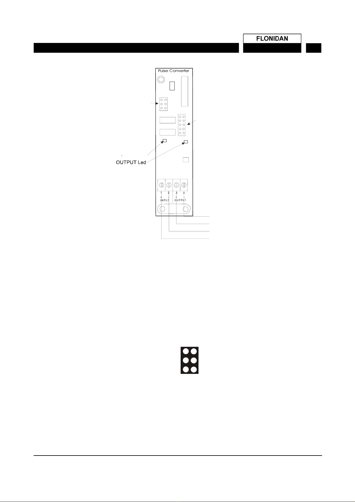
INPUT
+
FLONIDAN0618034REV.1
INPUT -
OUTPUT +
OUTPUT -
INPUT Led
INPUT meter
supply select
INPUT / OUTPUT
division select
Mount the 2 screws and strain relief securely. If it’s a shielded cable then terminate the shield under the
strain relief.
Turn on the power supply (first external supply and then battery).
Set up the parameters in Uniflo Config.
3.0 Functionality
3.1 General
The basic function of the Pulse divider option board is to repeat pulses received on the input port to the
output port.
Different types of meters can be interfaced to the input port by selecting different meter supply voltage.
The meter supply voltage is selected with a jumper placed on one of the three pin header pairs shown in the
picture:
14V
8V
5V
For typical types of meter inputs the voltage can be:
Reed, NPN: select 5V
Namur: select 8V
S01: select 14V
The Pulse divider option card can also divide the number of pulses received on the input port before it sends
pulses out on the output port.
U:\Hovedbibliotek\Produkter\Standard\Uniflo 1200\2. Kundemappe UK\5_Option board_Pulse in\5.3_Pulse_divider_card\Pulse divider
Board.doc
Page 5 of 6
PULSE DIVIDER
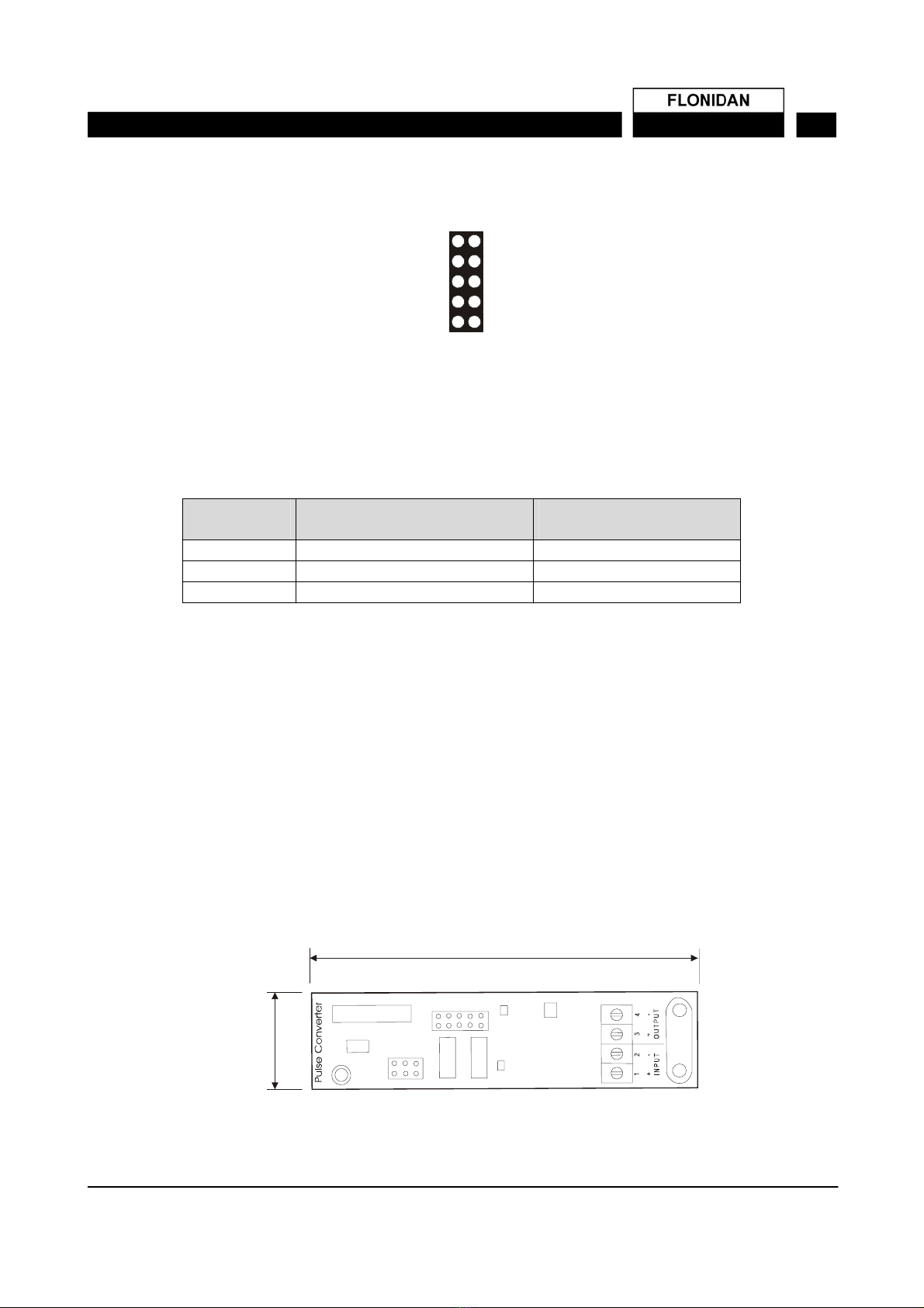
Its possible to select a division factor as 1, 10, 100, 1000 or 10000 with a jumper placed on one of the five
pin header pairs shown in the picture:
1 / 10000
1 / 1000
1 / 100
1 / 10
1 / 1
3.2 Power fail
If the power to the power supply fails the Pulse divider option board will stop counting/repeating pulses.
When the power returns the Pulse divider option board will start from zero if dividing is selected.
3.3 Max input frequency
The Pulse divider has the following data for max input frequency.
Typical meter
input
Selected meter supply Meter Min. frequency (50%
duty cycle)
LF 5 V 5000
Namur 8 V 5000
S01 14 V 5000
3.4 Diode LED's
Both the input and the output are equipped with a red diode LED to indicate the state of the input/output. The
LED will be on if the input is activated (current is running) and if the output is closed (current can run through
the optocoupler).
3.4 Supplied connectors with wires
The Pulse divider option board is delivered with two connectors wired up so it’s possible to connect Uniflo
1200 Output Pulse 1 or Output Pulse 2 to the Pulse divider option board Input (+ output to + input and –
output to – input).
4.0 Technical data
4.1 Dimensions
Drawing of Pulse divider option board
90 mm
20 mm
FLONIDAN0618034REV.1

U:\Hovedbibliotek\Produkter\Standard\Uniflo 1200\2. Kundemappe UK\5_Option board_Pulse in\5.3_Pulse_divider_card\Pulse divider
Board.doc
Page 6 of 6
PULSE DIVIDER
4.2 Common specifications
Required power: 5 VDC
17 VDC
Max. current 10 mA @ 5V
14 mA @ 17V ( Meter supply voltage / 1000 ohm)
Operating temperature: -30°C – 60°C
4.3 Markings
The Pulse divider option board has the following markings
Description Marking Explanation Example
Card type Pulse divider
Product number V.n.: 0618615-000
Serial number S/N: YYMMXXXX YY is production year
MM is production month
XXXX is consecutive card
number in each
production month
03060023
03 = year = 2003
06 = month = June
0023 = Card number 23
Revision history
Rev. Init Comment
23.07.2003 TF Document created
Flonidan DC A/S - Islandsvej 29 - DK-8700 Horsens
Other manuals for Uniflo 1200 GVEC
1
Table of contents


