FlorCraft 709-3914 User manual

7 in. Tile Wet Saw
OWNER’S MANUAL
Sierra para cortar losetas en húmedo de 180 mm
MANUAL DE OPERACIÓN
709-3914
READ AND FOLLOW ALL SAFETY AND
OPERATING INSTRUCTIONS BEFORE USING THIS SAW.
LEA Y SIGA TODAS LAS INSTRUCCIONES
DE FUNCIONAMIENTO Y SEGURIDAD ANTES DE USAR ESTA SIERRA.
E234797
WET TILE SAW
29FG
LEE ESTA INSTUCCION MANUAL
ANTES DE USA LA SIERRA PARA TU BIEN.
1. Siempre utilice gafas de protección al cortar.
2. Utilice una capota de protección para cada operación en la cual la puede utilizar.
3. Desconectar la sierra antes de limpiarla o antes de cambiar el disco de corte.
4. No utilice ningún disco de corte que tenga aperturas o ranuras. Solamente utilice discos
de corte lisos.
5. Reemplace el disco de corte cuando esté dañado.
6. No la exponga a la lluvia o no la utilice en áreas húmedas.
Este manual del usuario, contiene la
información necesaria para operar y
mantener su herramienta Sierra para
cortar losetas en húmedo de 180 mm
de manera segura y correcta. Por favor
tómese unos minutos para que usted se
familiarice con todos los contenidos en
este manual.
Si tiene alguna pregunta, siéntase libre
de llamar a nuestro Departamento de
Servicio al Cliente, llame gratis al:
866-435-8665. Por favor no se contacte
con el distribuidor.
Español .....................página 10
FOR YOUR OWN SAFETY, READ
INSTRUCTION MANUAL BEFORE OPERATING SAW.
1. Always wear safety goggles when cutting.
2. Use splash hood for every operation for which it can be used.
3. Disconnect saw before cleaning or changing blade.
4. Do not use any cutting blade with openings and grooves. Use only continuous rim blades.
5. Replace damaged blade before operating.
6. Do not expose to rain or use in damp locations.
This owner’s manual contains information
necessary to operate and maintain your 7"
Tile Wet Saw safely and correctly. Please
take a few minutes to familiarize yourself
with all the contents of this manual.
Should you have questions, feel free to
call our Customer Service Department,
toll free at: 866-435-8665. Please do not
contact the retailer.
English.........................page 1
1-YEAR LIMITED WARRANTY:
If during normal use, this FlorCraft™ tool breaks or fails due to a defect in material or workmanship within one year from
the original date of purchase, simply bring this tool and its original sales receipt to your nearest Menards®retail store
for a free equivalent replacement within that first year. This warranty: (1) excludes expendable parts including but not
limited to blades, bits, light bulbs, and/or batteries; (2) shall void if this tool is used for commercial and/rental purposes;
and (3) does not cover any losses, injuries to person/property or costs. This warranty does give you specific legal rights
and you may have other rights, which vary from state to state.
Servicio al cliente: 1-866-435-8665
1 AÑO DE GARANTÍA LIMITADA:
Si durante su uso normal, esta herramienta FlorCraft™ se daña o falla dado a un defecto en el material o en su
fabricación, dentro del año desde la fecha original de compra, simplemente traiga la herramienta y su recibo original de
compra a cualquiera de nuestros almacenes cercanos de Menards®para obtener un reemplazo equivalente dentro del
primer año. Esta garantía: (1) excluye a las partes sujetas a un desgaste usual, incluyendo pero no limitando como los
discos de corte, brocas, bombillos y/o baterías; (2) se anulará la garantía si utiliza la herramienta para un uso comercial
y para ser rentada; y (3) no se cubren perdidas, lesiones a personas o a propiedades ni a sus costos. Esta garantía sí le
da derechos legales específicos y usted podría tener otros derechos, los cuales varían de Estado a Estado.

– 1 –
SAFETY GUIDELINES
DEFINITIONS
WARNING ICONS: YOUR POWER TOOL
AND ITS INSTRUCTION MANUAL MAY
CONTAIN "WARNING ICONS" (A PICTURE
SYMBOL INTENDED TO ALERT YOU TO
AND/OR INSTRUCT YOU HOW TO AVOID A
POTENTIALLY HAZARDOUS CONDITION).
UNDERSTANDING AND HEEDING THESE
SYMBOLS WILL HELP YOU OPERATE YOUR
TOOL BETTER AND SAFER. SHOWN BELOW
ARE SOME OF THE SYMBOLS YOU MAY SEE.
SAFETY ALERT: Precautions that
involve your safety.
WEAR EYE PROTECTION: Always wear
safety goggles or safety glasses with side
shields.
WEAR RESPIRATORY AND HEARING
PROTECTION: Always wear respiratory and
hearing protection.
READ AND UNDERSTAND
INSTRUCTION MANUAL: To reduce the risk
of injury, user and all bystanders must read
and understand instruction manual before
using this product.
KEEP HANDS AWAY FROM THE
MOVING PART AND CUTTING SURFACE:
Failure to keep your hands away from the
moving part and cutting surface will result in
serious personal injury.
SUPPORT AND CLAMP WORK
WARNING Indicates a potentially
hazardous situation which, if not avoided,
could result in death or serious injury.
CAUTION Indicates a potentially
hazardous situation which, if not avoided,
may result in minor or moderate injury.
GENERAL SAFETY
INSTRUCTIONS
READ THIS OWNER'S
MANUAL COMPLETELY AND MAKE
SURE YOU UNDERSTAND ALL OF ITS
SAFETY GUIDELINES.
1. KEEP GUARDS IN PLACE and in
working order.
2. REMOVE ADJUSTING KEYS AND
WRENCHES. Before turning on the tile saw,
make sure the keys and adjusting wrenches
have been removed.
3. KEEP WORK AREA CLEAN. Cluttered areas
and benches invite accidents.
4. ALWAYS REMAIN ALERT WHEN THE SAW
IS IN USE. Inattention on the part of the
operator may lead to serious injury.
5. DON’T USE IN A DANGEROUS
ENVIRONMENT. Don’t use power tools in
damp or wet locations or expose them to
rain. Keep work area well lit.
6. KEEP CHILDREN AWAY. All visitors should
remain at a safe distance from work area.
7. MAKE WORKSHOP CHILD PROOF with
padlocks, master switches or by removing
starter keys.
8. USE THE RIGHT TOOL. Don’t force a tool
or attachment to do a job for which it was
not designed.
9. USE THE PROPER EXTENSION CORD.
Make sure your extension cord is in good
condition. When using an extension cord,
be sure to use one heavy enough to carry
the current your product will draw. An
undersized cord will cause a drop in line
voltage resulting in loss of power and
overheating. TABLE 1 (page 2) shows the
correct size to use depending on cord length
and nameplate ampere rating. If in doubt,
use the next heavier gauge. The smaller the
gauge number, the heavier the cord.
10. DON’T FORCE THE TOOL. It has been
designed to operate at maximum safety and
performance levels.
11. DO NOT FORCE THE MATERIAL BEING
CUT. Always let the blade cut at its own
speed.
12. WEAR PROPER APPAREL. Do not wear
loose clothing, neckties, rings, bracelets
or other jewelry which may get caught
in moving parts. Non-slip foot wear is
recommended. Wear protective hair
covering if you have long hair.
7 in. Tile Wet Saw
709-3914
13. ALWAYS USE SAFETY GLASSES. Also
use face or dust mask for commercial
cutting operations. Everyday eyeglasses only
have impact-resistant lenses, they are NOT
safety glasses.
14. DON’T OVERREACH. Keep proper footing
and balance at all times.
15. MAINTAIN TOOLS WITH CARE. Keep
tools clean and in good working condition for
maximum safety performance.
16. DISCONNECT SAW BEFORE SERVICING –
when changing accessories, such as blades,
bits, cutters, etc.
17. REDUCE THE RISK OF UNINTENTIONAL
STARTING. Make sure switch is in OFF
position before plugging in.
18. USE RECOMMENDED ACCESSORIES.
Consult the owner’s manual for recommended
accessories. The use of improper accessories
may increase risk of injury.
19. DO NOT DRY CUT WITH BLADES
DESIGNED FOR WET CUTS.
20. Make sure you USE THE CORRECT
BLADE for the job you are doing.
21. NEVER STAND ON TOOL. Serious injury
could occur if the wet saw is tipped or if the
cutting tool is unintentionally contacted.
22. CHECK DAMAGED PARTS. Before
further use of the tool, damaged part(s),
(i.e., guard) should be carefully checked
to determine that it will operate properly
and perform its intended function. Check
for alignment of moving parts, binding of
moving parts, breakage of parts, mounting
and any other condition that may affect the
saw’s operation. A guard or other part that
is damaged should be properly repaired
or replaced.
23. Ensure that BLADE IS TRAVELING
THROUGH WATER RESERVOIR FOR WET
CUTTING.
24. CHECK DIAMOND BLADES carefully
for cracks, nicks, missing diamond matrix
or out-of-alignment condition. Replace
damaged blades immediately. DO NOT USE
DAMAGED BLADES. They may cause bodily
injury.
25. DIRECTION OF FEED. Feed work into the
blade against the direction of rotation of the
blade only.
26. DO NOT ALTER THE PLUG or use a
2-prong receptacle. This saw is equipped
with a 3-prong electrical plug.
27. NEVER LEAVE SAW RUNNING
UNATTENDED. Turn power off. Don’t leave
tool until it comes to a complete stop.
TABLE OF CONTENTS
Safety guideline definitions................1
General safety instructions................1
Electrical requirements . . . . . . . . . . . . . . . . . . . 2
Extension cords..........................2
California Prop 65 ........................ 2
Product specifications....................3
Parts list ................................3
Assembly instructions .................... 3
Laser guide..............................4
Operating instructions & guide............5-6
Maintenance . . . . . . . . . . . . . . . . . . . . . . . . . . . . 6
Troubleshooting..........................7
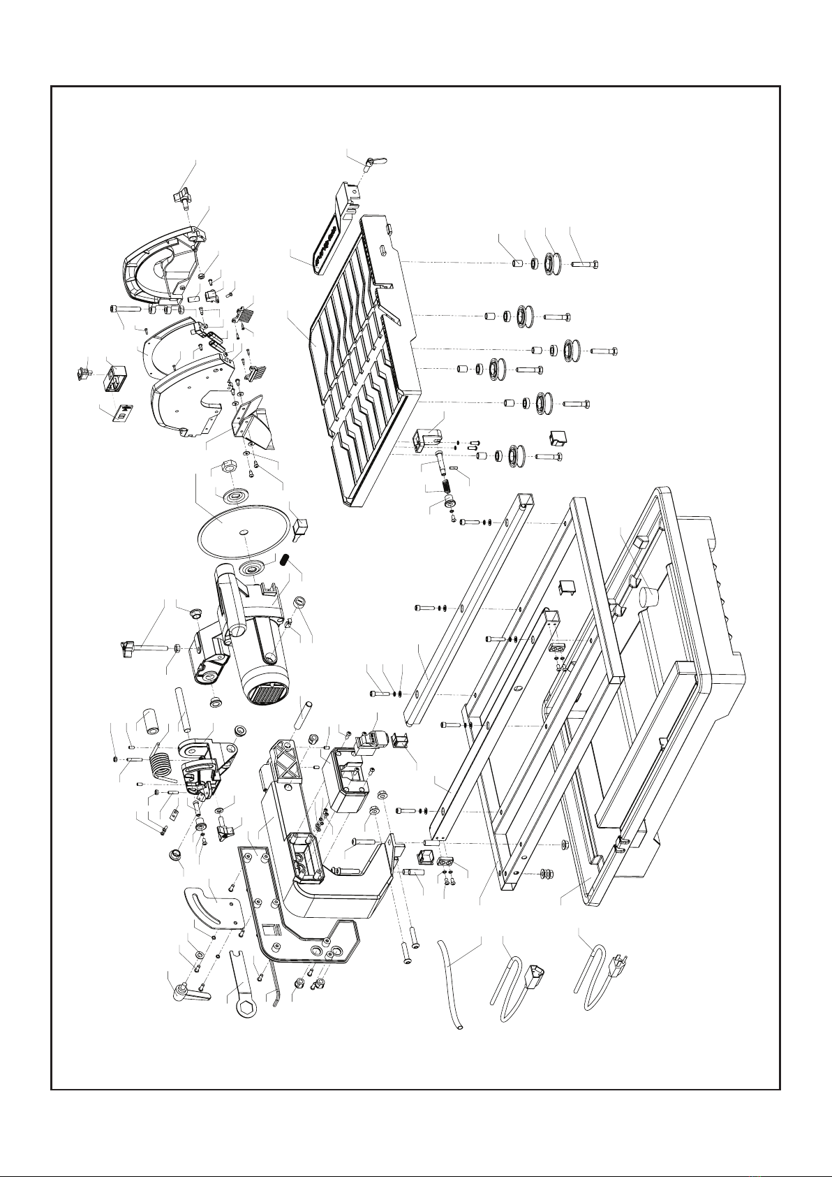
Exploded Diagram.......................8-9

– 2 –
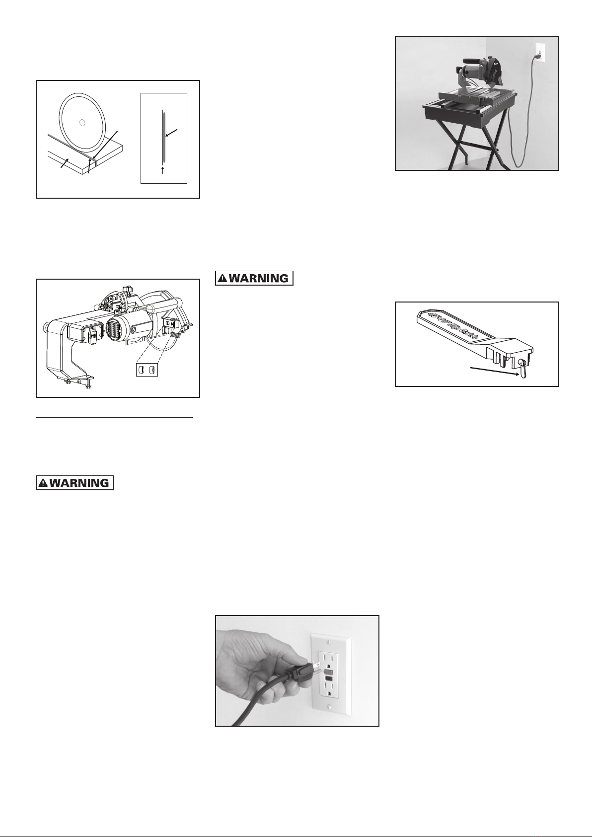
28. POSITIONING OF TILE SAW
(see FIGURE 1)
Drip
Loop
FIGURE 1
• To avoid the possibility of the appliance
plug or receptacle getting wet, position
the tile saw to one side of a wall-mounted
receptacle to prevent water from dripping
onto the receptacle or plug. The user
should arrange a “drip loop” in the cord
connecting the saw to a receptacle. The
“drip loop” is that part of the cord below
the level of the receptacle, or connector if
an extension cord is used, to prevent water
traveling along the cord and coming in
contact with the receptacle.
• If the plug or receptacle does get wet, DO
NOT unplug the cord. Disconnect the fuse
or circuit breaker that supplies power to
the tool. Then, unplug and examine for
presence of water in the receptacle.
PERSONAL INJURY
CAN OCCUR IF OPERATED IMPROPERLY.
• Keep fingers and loose clothing away from
rotating blade.
• Use extreme caution when cutting tile.
Make sure hands and fingers are clear
from the blade groove in the table. Severe
abrasion, cuts, or pinching of hands or
fingers can occur as the table is advanced,
particularly at the end of its travel.
• Electrical shock can occur if operating
instructions are not followed.
FOR YOUR OWN SAFETY READ
INSTRUCTION MANUAL BEFORE
OPERATING SAW.
• Wear eye protection.
• Use blade guard for every operation for
which it can be used.
• Unplug saw before servicing, when
changing cutting wheels, and cleaning.
• Use tool only with smooth-edge cutting
wheels free of openings and grooves.
• Replace damaged cutting wheel
before operating.
• Do not fill water tray above water fill line.
ELECTRICAL
REQUIREMENTS
1. THIS TILE SAW MUST BE CONNECTED TO
A GROUNDED POWER SOURCE while in use
to protect the operator from electrical shock.
2. IN THE EVENT OF A MALFUNCTION OR
BREAKDOWN, grounding provides a path
of least resistance for electrical current to
reduce the risk of electrical shock. This tile
saw is equipped with an electrical cord with
a grounding conductor and a grounding
plug. Insert the 3-prong electrical plug into
a 3-pole receptacle that is properly installed
and grounded in accordance with all local
codes and ordinances.
3. DO NOT MODIFY THE PLUG provided if it
will not fit the outlet. Have the proper outlet
installed by a qualified electrician.
4. IMPROPER CONNECTION OF THE
EQUIPMENT-GROUNDING CONDUCTOR
CAN RESULT IN A RISK OF ELECTRIC
SHOCK. The conductor with insulation that
is green on the outside (with or without
yellow stripes) is the equipment-grounding
conductor. If repair or replacement of the
electrical cord or plug is necessary, do not
connect the equipment-grounding conductor
to a live terminal.
5. CHECK WITH A QUALIFIED ELECTRICIAN
or service personnel if the grounding
instructions are not completely understood,
or if in doubt as to whether the tool is
properly grounded.
6. USE ONLY 3-WIRE EXTENSION CORDS
that have 3-prong grounding plugs and
3-pole receptacles that accept the tile saw’s
plug.
7. REPAIR OR REPLACE DAMAGED OR
WORN CORD IMMEDIATELY.
8. IF THE PLUG OR RECEPTACLE DOES
GET WET, DO NOT UNPLUG THE CORD.
Disconnect the fuse or circuit breaker that
supplies power to the tool. Then, unplug and
examine for the presence of water in the
receptacle.
9. ONLY UL-LISTED EXTENSION CORDS
SHOULD BE USED WITH THIS PRODUCT.
10. IMPROPER USE OF EXTENSION CORDS
MAY CAUSE INEFFICIENT OPERATION OF
YOUR TOOL, which can result in overheating.
Be sure your extension cord is rated to allow
sufficient current flow to the motor. For the
proper gauge for this tile saw, please refer
to TABLE 1.
11. DO NOT LET YOUR FINGERS TOUCH
THE TERMINALS of plug when installing or
removing the plug to or from the outlet.
12. THIS TILE SAW MUST BE PROPERLY
GROUNDED. The risk of electric shock and
bodily injury are greatly increased if it is not,
particularly when used in damp locations or
in proximity to plumbing.
NOTE: This saw is intended for use on a
circuit that has a grounded outlet box like
the one illustrated in FIGURE 2 (B). This saw
has a grounding plug that looks like the one
illustrated in FIGURE 2 (A).
Metal
screw
(B) Grounded
outlet box
(A) Grounding pin
FIGURE 2
EXTENSION CORDS
TO REDUCE THE
RISK OF ELECTROCUTION, KEEP ALL
CONNECTIONS DRY AND OFF THE GROUND.
DO NOT TOUCH PLUG WITH WET HANDS.
1. Use only extension cords that are intended
for outdoor use. These extension cords are
identified by a marking “Acceptable for use
with outdoor appliances: store indoors while
not in use.” Use only extension cords having
an electrical rating not less than the rating of
the product. Do not use damaged extension
cords. Examine extension cord before using
and replace if damaged. Do not abuse
extension cords and do not pull on any
cord to disconnect. Keep cord away from
heat and sharp edges. Always disconnect
the extension cord from the receptacle
before disconnecting the product from the
extension cord.
2. Ground Fault circuit Interrupter (GFCI)
protection should be provided on the
circuit(s) or outlet(s) to be used for the tile
saw. Receptacles are available having
built-in GFCI protection and may be used for
this measure of safety.
3. USE PROPER EXTENSION CORD. Make
sure your extension cord is in good
condition. When using an extension cord,
be sure to use a cord heavy enough to
carry the current your product will draw.
An undersized cord will cause a drop in line
voltage, resulting in a loss of power and
overheating. TABLE 1 shows the correct
size to use depending on cord length and
nameplate ampere rating. If in doubt, use the
next heavier gauge. The smaller the gauge
number, the heavier the cord.
NOTE: When using an extension cord,
ensure all cords are no smaller than #12
gauge, rated at a 20-amp minimum, and
equipped with 3-prong plugs. Use of
anything smaller may result in overheating or
burn out of the motor. It is recommended to
have an electrician check the voltage at the
saw motor to ensure proper voltage to run
the saw efficiently and safely.
CALIFORNIA
PROPOSITION 65
SOME DUST CREATED
BY POWER SANDING, SAWING, GRINDING,
DRILLING AND OTHER CONSTRUCTION
ACTIVITIES CONTAIN CHEMICALS KNOWN
TO THE STATE OF CALIFORNIA TO CAUSE
CANCER, BIRTH DEFECTS OR OTHER
REPRODUCTIVE HARM.
Some examples of these chemicals are:
• Lead from lead-based paints
• Crystalline silica from bricks, cement and
other masonry products
• Arsenic and chromium from chemically-
treated lumber
TABLE 1
Ampere rating
Volts Total length of cord in feet
120 V 25 ft. 50 ft. 100 ft. 150 ft.
240 V 50 ft. 100 ft. 200 ft. 300 ft.
More than No more than AWG
0 6 18 16 16 14
6 10 18 16 14 12
10 12 16 16 14 12
12 16 14 12 Not recommended
– 3 –
Your risk from these exposures varies,
depending on how often you do this type
of work. To reduce your exposure to
these chemicals: work in a well ventilated
area, and work with approved safety
equipment, such as those dust masks
that are specifically designed to filter out
microscopic particles.
DESCRIPTION
Before attempting to use any tool, be sure
to familiarize yourself with all the operating
features and safety instructions.
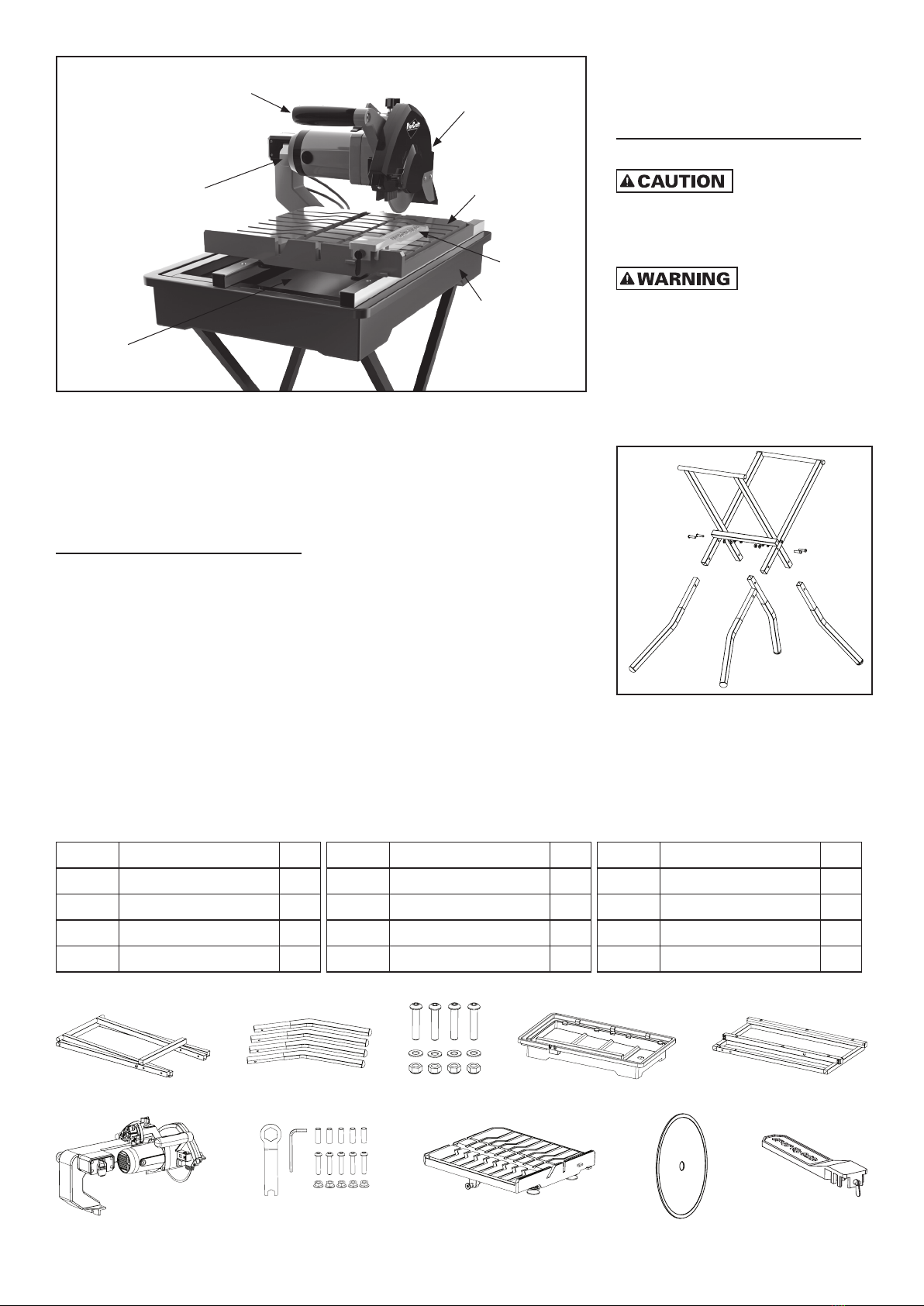
KNOW YOUR SAW
Your tile saw has many built-in features
(see FIGURE 3) for fast and efficient cutting
of ceramic, porcelain, marble, slate or
limestone wall or floor tile.
PRODUCT SPECIFICATIONS
MOTOR
Input: 9.5 Amps
Output: 1½ -Peak HP
Rating: 120 Volts~60 Hz AC
No-load Speed: 6000 RPM
Power Cord: 6'
SAW
Blade Diameter: 7 in. (180 mm)
Blade Type: Continuous Rim Diamond Blade
Arbor Size: 5/8"
Machine Weight: 52 Lbs. (23.6 kg)
CUTTING CAPACITIES
Bevel Cut Range: 0°–45°
Adjustable Depth of Cut: Up to 2-1/4" (5.7 cm)
Maximum Rip Cut: 24" (61 cm)
Maximum Diagonal Cut: 18" (45.7 cm)
CUTTING ACCESSORIES
Laser Guide
Adjustable Miter Guide & Rip Fence
FOLDING STAND
Dimensions: 17-3/4" W x 28-3/8" L
(45 cm x 72 cm)
Stand Height: 35-1/4" or 38-1/3"
(90 cm or 97 cm)
ASSEMBLY
FOLLOW ALL
OF THE ASSEMBLY AND OPERATION
INSTRUCTIONS COMPLETELY BEFORE
CONNECTING THE SAW TO A POWER
SOURCE OR TURNING THE MOTOR ON.
IF ANY PARTS ARE
DAMAGED OR MISSING, DO NOT ATTEMPT
TO OPERATE THIS SAW. OPERATING THIS
SAW WITH DAMAGED OR MISSING PARTS
COULD RESULT IN POSSIBLE SERIOUS
PERSONAL INJURY.
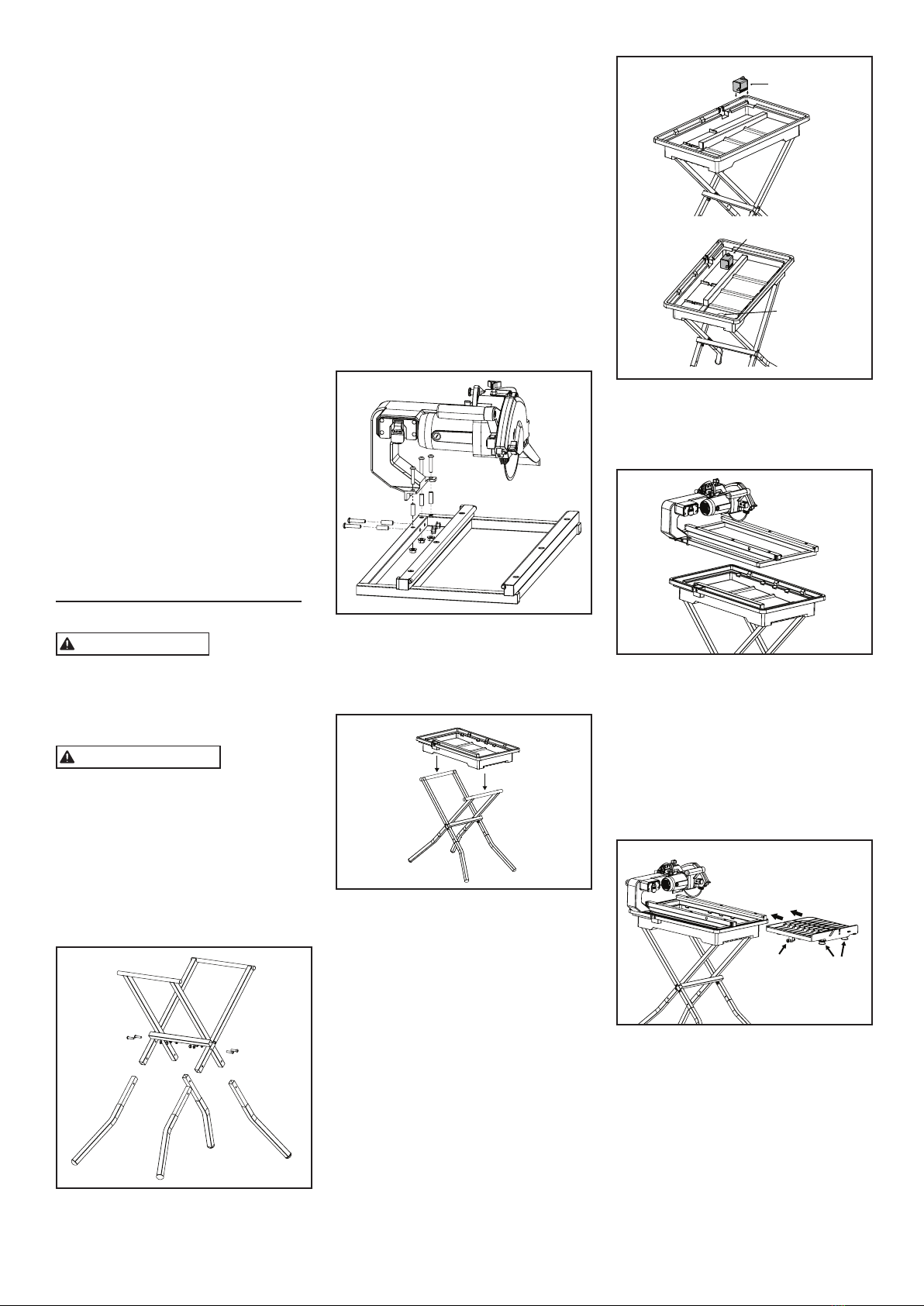
ASSEMBLING THE STAND
1. Insert the 4 stand tubes (B) into the stand
frame (A). (see FIGURE 4)
FIGURE 4
2. Place the 4 screws & washers through the
pre-drilled holes (C).
3. Secure with nuts (C).
FIGURE 3
Rip/Angle
Guide
Blade Guard
Cutting Table
Bottom
Cord Storage
On/Off
Switch/Key
Handle
Water Reservoir
AB
CE
F
D
L
G I
H
K
J
PART # DESCRIPTION Qty
A Stand Frame 1
B Stand Tubes 4
C Screws, Washers, & Nuts 4
D Tray 1
PART # DESCRIPTION Qty
E Frame 1
F Motor with Arm Assembly 1
G Hex Wrench 1
H Allen Wrench 1
PART # DESCRIPTION Qty
I Pin, Screws, & Nuts 5
J Table 1
K Blade 1
L Rip/Angle Guide 1

– 4 –
ASSEMBLING THE ARM
1. Align the holes in the arm (F) with the
holes on the left of the frame (E)
(see FIGURE 5).
2. Put 3 pins (I) into the holes on the arm.
3. Insert 3 screws and nuts (I) and slightly
tighten nuts from the back of the frame.
4. Place 2 pins (I) into the holes on the left of
the arm.
5. Insert 2 screws and nuts (I) and slightly
tighten nuts from the back of the frame.
6. Tighten the 2 nuts on the arm, then tighten
the 3 nuts below on frame.
FIGURE 5
INSTALLING THE TRAY
1. Place the tray onto the stand. (see FIGURE 6)
FIGURE 6
INSTALLING THE WATER PUMP
(see FIGURE 7)
1. Place the pump in its designated location
inside the water tray.
2. Make sure drain plug is secured.
3. Plug the pump power cord into the 3-prong
receptacle on the side of the cutting head
assembly.
4. Make sure that the water valve
connecting the pump to the tubing is in the
full open position.
Water Pump
Water Pump
Drain Hole
FIGURE 7
ASSEMBLING THE SAW
1. Place the motor fixed to the frame into the
top of the tray. (see FIGURE 8)
FIGURE 8
ASSEMBLING THE TABLE
(see FIGURE 9)
1. Unlock the pin lock on the side of table (J)
– pull and turn 90°.
2. Align the wheels under the table to the
tray guide rails.
3. Slide the table (J) into the tray guide rails.
4. Secure pin lock in place on table (J) side –
push and turn 90°.
Wheels
Table Lock
FIGURE 9
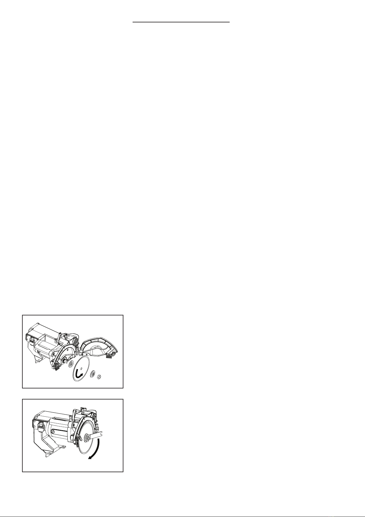
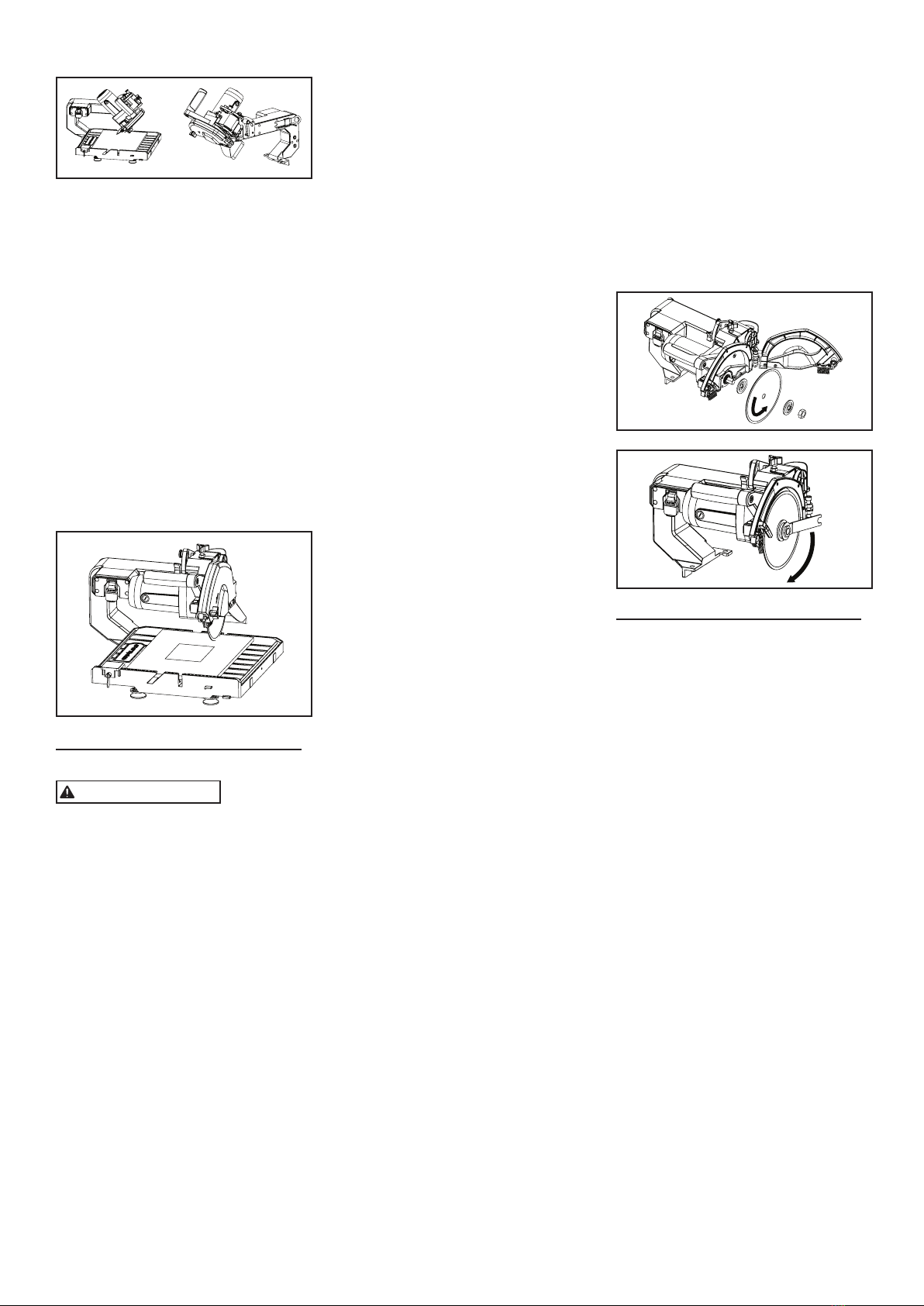
ASSEMBLING THE BLADE
1. Remove the inner flange and outer flange
from the arm (F). (see FIGURE 10A)
2. Place the inner flange, blade (K), and outer
flange onto the shaft. (see FIGURE 10B)
3. Secure with nut and tighten.
Blade
Rotation
FIGURE 10A
Tighten
FIGURE 10B
LASER GUIDE
FOR YOUR OWN
SAFETY, NEVER CONNECT THE PLUG TO A
POWER SOURCE OUTLET UNTIL ALL THE
ADJUSTMENT STEPS ARE COMPLETE
AND YOU HAVE READ AND UNDERSTOOD
THE SAFETY AND OPERATIONAL
INSTRUCTIONS.
• LASER RADIATED WHEN LASER GUIDE
IS TURNED ON. AVOID DIRECT EYE
CONTACT.
• ALWAYS UNPLUG THE TILE SAW FROM
POWER SOURCE BEFORE MAKING ANY
ADJUSTMENTS.
• THE USE OF CONTROLS, ADJUSTMENTS,
OR PERFORMANCE OF PROCEDURES
OTHER THAN THOSE SPECIFIED HEREIN
MAY RESULT IN HAZARDOUS RADIATION
EXPOSURE.
• THE USE OF OPTICAL INSTRUMENTS
WITH THIS PRODUCT WILL INCREASE
EYE HAZARD.
• DO NOT ATTEMPT TO REPAIR
OR DISASSEMBLE THE LASER. IF
UNQUALIFIED PERSONS ATTEMPT
TO REPAIR THIS LASER PRODUCT,
SERIOUS INJURY MAY RESULT. ANY
REPAIR REQUIRED ON THIS LASER
PRODUCT SHOULD BE PERFORMED
BY AUTHORIZED SERVICE CENTER
PERSONNEL.
NOTE: Your tool is equipped with a laser
guide using a laser beam. The laser beam
will enable you to preview the saw blade
path on the tile to be cut before starting the
saw. (see FIGURE 11)
• If you choose to use the laser guide, the
laser beam must be correctly aligned with
the blade to ensure straight, even cutting.
– 5 –
• The laser on/off switch must be turned on
for the laser line to show.
• This laser guide is powered by two AG13
(1.5V) button cell batteries.
Laser Beam
Cutting Line
Blade
Tile Laser Beam
Blade
TOP VIEW
FIGURE 11
INSERTING AND REPLACING THE
LASER BATTERIES
(see FIGURE 12)
1. Open the cover of the battery box.
2. Place the 2 button cell batteries in before
turning on the laser beam.
FIGURE 12
OPERATION
IMPORTANT: ALWAYS turn off the saw and
remove the plug from the outlet BEFORE
adding or removing accessories and making
adjustments.
FAILURE TO UNPLUG
THE SAW COULD RESULT IN ACCIDENTAL
STARTING CAUSING POSSIBLE SERIOUS
PERSONAL INJURY.
BEFORE STARTING THE SAW
1. Make sure saw is unplugged.
2. Pour water into the tray and fill water level
higher than the pump intake nozzle.
NOTE: ALWAYS keep enough water in the
reservoir when operating the saw. DO NOT
let the saw run dry.
3. IMPORTANT: ALWAYS completely drain
the water reservoir and clean thoroughly
after each use
1. Ensure that the directional arrow marked
on the blade corresponds with the rotation
of the motor.
2. With the saw disconnected from the
power supply, rotate the blade by hand to
ensure it is free from obstruction.
3. Always keep the blade-securing arbor and
collars clean.
4. Ensure that the blade-securing bolt is
securely tightened.
5. NEVER try to cut freehand. Always ensure
that the tile to be cut is pressed firmly
against the rip fence.
6. Ensure the tile that will be cut off has
sufficient room to move sideways. Failure
to do so may result in the off-cut binding
against the blade.
7. NEVER cut more than one tile at a time.
8. NEVER cut pieces so small that it cannot
be held securely against the rip fence, and
provide enough space for the hand to be a
safe distance from the blade.
9. Ensure that the table and surrounding area
are clear with the exception of the tile to be
cut.
10. Before cutting a tile piece, let the saw
blade run freely for a few seconds. If it
makes an unfamiliar sound or vibrates
excessively, switch it off immediately and
disconnect it from the power supply.
11. Let the blade reach full speed before
starting the cut.
12. Let the blade come to a complete stop
before removing any jammed material from
around the blade area.
13. NEVER allow the blade to run dry. Failure
to keep the water tray at the recommended
level will result in possible over-heating of
the diamond blade.
PERSONAL INJURY
CAN OCCUR IF OPERATED IMPROPERLY.
• Before turning the tile saw on, verify the
alignment of the cutting table and the
cutting blade. (Always center the cutting
blade in one of the cutting table grooves
before cutting).
• Keep fingers and loose clothing away
from rotating blade.
• Use extreme caution when cutting tile.
Make sure hands and fingers are clear
from the blade groove in the table.
• Electrical shock can occur if operating
instructions are not followed. FOR YOUR
OWN SAFETY READ INSTRUCTION
MANUAL BEFORE OPERATING SAW.
• Wear eye protection.
• Use blade guard for every operation for
which it can be used.
• Unplug saw before servicing, when
changing cutting wheels, and cleaning.
• Use tool only with smooth-edge cutting
wheels free of openings and grooves.
• Replace damaged cutting wheel before
operating.
• Do not fill water tray above water fill line.
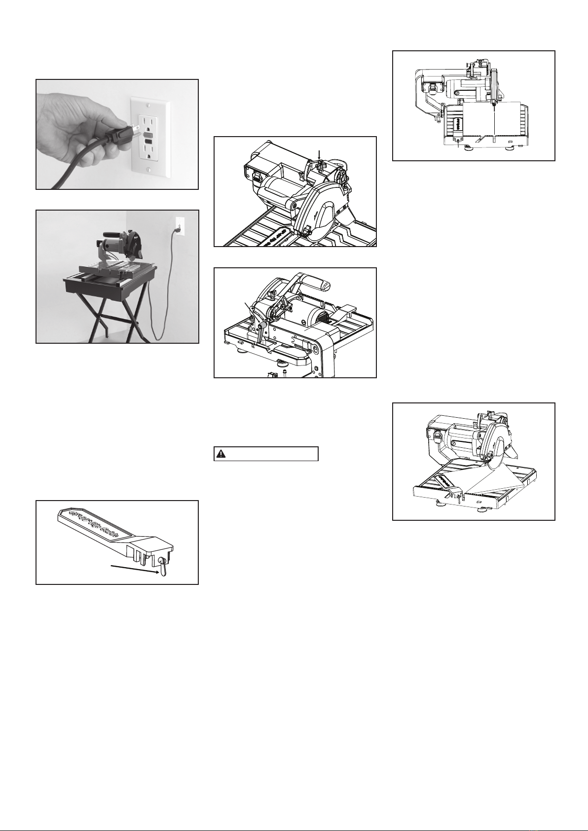
TO START THE SAW
1. Plug the saw in to a GFCI (Ground Fault
Circuit Interrupter) protected outlet (see
FIGURE 13).
2. Create “drip loop” in the cord
(see FIGURE 14).
FIGURE 13
Drip
Loop
FIGURE 14
USING THE RIP/ANGLE
GUIDE
The miter scale on the Rip/Angle guide can
be easily read, showing 45° miter angles.
1. Loosen the locking handle to move the
guide along the front rail to the desired
position and handle. (see FIGURE 15)
2. Loosen the locking knob to turn the guide
to the desired angle along the arc slot.
3. Tighten the locking knob.
Locking Knob
FIGURE 15
ADJUSTING THE CUTTING
HEAD
RAISE THE CUTTING HEAD
1. Always turn the saw OFF when raising or
pressing down the cutting head.
2. Loosen the blade elevation locking knob.
(see FIGURE 16)
3. Lift the handle upward to raise the cutting
head.
4. Once the cutting head has been raised
to the desired height, tighten the blade
elevation locking knob to lock.
5. When transporting or storing the tile saw,
the cutting head should always be locked in
the low position.
TILTING THE CUTTING HEAD
1. To tilt the blade for bevel cutting, loosen
the blade tilting locking knob behind the
motor head. (see FIGURE 17)
2. Firmly grasp the handle and tilt the cutting
head by turning the handle clockwise.
3. Tighten the blade tilting locking knob.

– 6 –
6. Slowly lower the cutting head to make a
cut on the tile, then raise the cutting head.
7. Turn the tile saw off.
FIGURE 21
MAINTENANCE
TO AVOID
ACCIDENTS, ALWAYS DISCONNECT
THE TOOL FROM THE POWER SOURCE
BEFORE CLEANING OR PERFORMING ANY
MAINTENANCE
• Do not try to service this machine on your
own.
• Avoid using solvents when cleaning
plastic parts. Most plastics are
susceptible to damage from various
types of commercial solvents and may be
damaged by their use.
• Always use a clean cloth to remove dirt,
carbon dust, etc.
• Always clean the tile saw after each use
and store it in a dry location.
• Always wipe off all exterior surfaces and
keep the cutting table clean and free of all
debris.
• Always check the blade for cracks or
damage before each use.
WATER PUMP
1. Disconnect the power before maintenance
of the pump.
2. Disassemble the water pump to see if any
cracks or dirt are inside.
3. Check if the water tubing is clogged where
the water cannot flow. Clear the tubing with
warm water.
4. Make sure pump is plugged in during use.
5. Make sure the in-take sponge filter is
cleaned after each use.
6. Run clean/ fresh water for one minute
through the water pump and the blade guard
to prevent waste build-up and clogging.
7. Do not run the pump without water.
DIAMOND BLADES
• Use only 7 in. (180 mm) continuous rim
diamond blades with a 5/8" arbor opening
in this saw. Failure to do so may result in
severe bodily injury and damage to the
saw.
• The diamond blade that comes with
this saw will cut ceramic, porcelain and
marble tile. Due to the hardness of some
porcelain, slate and stone, purchasing a
blade specifically designed to cut these
hard tiles, will speed up the cutting time
required. IMPORTANT: Always let the blade
cut at its own speed, moving the material
slowly into the blade. Do not force the
material being cut.
Elevation Knob
FIGURE 16
Tilt Knob
FIGURE 17
MAKING CUTS
The edge of the cutting table has
easy-to-see dimensions (in both inches and
centimeters) for cutting accuracy.
USE ONLY
CONTINUOUS RIM BLADES WITH THIS
SAW. DO NOT USE SEGMENTED, “TURBO”
BLADES, WOOD SAWING BLADES, BLADES
WITH OPENINGS, OR ANY OTHER CUTTING
DEVICES WITH THIS TILE SAW. USING
THESE BLADES COULD RESULT IN SERIOUS
PERSONAL INJURY AND DAMAGE TO THE
SAW.
IMPORTANT: ALWAYS LET THE BLADE CUT
AT ITS OWN SPEED. DO NOT FORCE THE
MATERIAL BEING CUT. ALWAYS CHECK THE
BLADE FOR CRACKS OR DAMAGE BEFORE
EACH USE.
MAKING 90° RIP CUTS
1. Using a pencil or China marker, mark the
area to be cut on tile.
2. Place the tile on the cutting table against
the Rip/Angle guide and align the mark with
the cutting blade. (see FIGURE 18)
3. Turn the tile saw on, allow the cutting
blade to reach full speed and wait until
the stream of water from the water nozzle
completely covers the cutting blade.
4. Use both hands to slowly push the cutting
table toward the cutting blade to feed the tile
into the cutting blade.
5. Turn the tile saw off.
FIGURE 18
MAKING DIAGONAL CUTS
(see FIGURE 19)
1. Using a pencil or China marker, mark the
area to be cut on tile.
2. Loosen the locking handle to move the
Rip/Angle guide along the front rail to the
desired position, then tighten the handle.
3. Loosen the locking knob to turn the guide
to the desired angle along the arc slot, then
tighten the knob.
4. Turn the tile saw on, allow the cutting
blade to reach full speed, and allow the
stream of water from the water nozzle
completely cover the cutting blade.
5. Use both hands to slowly push the cutting
table toward the cutting blade to feed the tile
into the cutting blade.
6. Turn the tile saw off.
FIGURE 19
MAKING BEVEL MITER CUTS
(see FIGURE 20)
1. Using a pencil or China marker, mark the
area to be cut on tile.
2. Loosen the blade elevation locking knob to
raise the cutting head, then tighten the knob.
3. Loosen the blade tilting locking knob to tilt
the cutting head 45° clockwise, then tighten
the knob.
4. Loosen the blade elevation locking knob to
lower the cutting head in the miter slot in the
table, then tighten the knob.
5. Turn the tile saw on, allow the cutting
blade to reach full speed, and allow the
stream of water from the water nozzle
completely cover the cutting blade
6. Use both hands to slowly push the cutting
table toward the cutting blade to feed the tile
into the cutting blade.
7. Turn the tile saw off.
FIGURE 20
PLUNGE CUTS
(see FIGURE 21)
1. Using a pencil or marker, mark the area to
be cut on tile.
2. Loosen the blade elevation locking knob
to raise the cutting head upward to the
maximum height.
3. Turn the tile saw on, allow the cutting
blade to reach full speed, and allow the
stream of water from the water nozzle
completely cover the cutting blade.
4. Hold the cutting head firmly by the handle.
5. Move the tile on the cutting table in to
place underneath the cutting blade.
– 7 –
DIAMOND BLADE DO’S &
DON’TS
1. DO inspect blades daily for cracks or
uneven wear. Discard cracked, chipped or
bent blades!
2. DO use manufacturer’s recommendation
for matching the right blade with the right
material being cut.
3. DO inspect the arbor shaft for uneven
wear before mounting the blade.
4. DO use blades with the correct arbor size
on a compatible arbor shaft.
5. DO ensure the blade is mounted with the
rotation arrow in the proper direction and is
securely tightened with a wrench.
6. DO wear proper safety equipment at
all times when operating the saw. Wear
goggles and dust mask at all times when
operating saw.
7. DO periodically check the blade for cracks
or bond fatigue.
8. DO ensure that blade is traveling through
water reservoir for wet cutting.
1. DO NOT operate the saw without all safety
guards in position.
2. DO NOT operate the saw with blades
larger or smaller than recommended.
3. DO NOT cut dry with blades marked
“Use Wet.”
4. DO NOT exceed maximum RPMs
recommended by the blade manufacturer.
5. DO NOT force the material into the blade.
Let the blade cut at its own speed.
6. DO NOT cut material not recommended by
the blade manufacturer.
REPLACING THE BLADE
1. Remove the outer flange with wrench.
2. Ensure that the shaft and flanges are
clean.
3. Mount blade on to shaft with the
directional arrow on the blade rotating in the
same direction as the motor
(see FIGURE 22A)
4. Replace flange, lock nut, and tighten.
(see FIGURE 22B)
Blade
Rotation
FIGURE 22A
Tighten
FIGURE 22B
TROUBLESHOOTING
OVERHEATING OF SAW:
1. Turn saw off and let it rest until motor is
cool to the touch.
2. Check and clean the ventilation slots,
removing blockage and dirt.
THE SAW DOES NOT START:
1. Check that power cord is properly
plugged in.
2. Check outlet power source and circuit
breaker.
WATER IS NOT FLOWING:
1. Make sure water level in tray is high
enough to clear the intake nozzle.
2. Make certain the water valve connecting
the pump to the tubing is in the “ON”
position.
3. Check water hose for connection or clogs.
4. Check that the power cord is plugged in
properly.
5. Check for excess debris on intake filter.
THE CUTTING TABLE IS NOT
SLIDING SMOOTHLY:
1. Thoroughly clean guide rails.
CUSTOMER SERVICE:
1-866-435-8665

– 8 –
PARTS LIST
See exploded parts (p. 9)
PART # DESCRIPTION Qty
6-7003Q Blade 1
709-3914-1 Knob 1
709-3914-2 Blade Guard Cover 1
709-3914-3 Hexagon Nut M6 1
709-3914-4 Hexagon Socket Head
Cap Screws M8*50mm 1
709-3914-5 Cross recessed
countersunk head tapping
screws ST2.9*10-F 7
709-3914-6 Pipe Cover 1
709-3914-7 Battery Box For Laser
Beam 1
709-3914-8 Switch For Laser Beam 1
709-3914-9 Cover of Battery Box 1
709-3914-10 Locking Nut M8 1
709-3914-11 Laser Beam 1
709-3914-12 Cross recessed Pan head
tapping screws ST2.9*10-F 1
709-3914-13 Laser Beam Fixer 1
709-3914-14 Cross recessed
countersunk head tapping
screws ST4.2*10-F 1
709-3914-15 Head of Sprays 1
709-3914-16 Extension of the Head of
Sprays 2
709-3914-17 Hexagon Nut M4 1
709-3914-18 Blade Guard 1
709-3914-19 Brush 2
709-3914-20 Cross Recessed Pan Head
Screw M4*10mm 1
709-3914-21 Cross Recessed Pan Head
Screw M5*15mm 13
709-3914-22 Spray Baffle 1
709-3914-23 Hexagon Nut M6 1
709-3914-24 Outer Flange 1
709-3914-26 Inner Flange 1
709-3914-27 Plain Washer 4
709-3914-28 Cross Recessed Pan Head
Tapping Screw ST4.2*10-F 4
709-3914-29 Anti-spining Button 1
709-3914-30 Spring 1
709-3914-31 Motor 1
PART # DESCRIPTION Qty
709-3914-65 Lock Washers Internal
Teeth 2
709-3914-66 Hexagon Socket Flat Button
Head Screw M8*40mm 5
709-3914-67 Hexagon Nuts with Flange
M8 5
709-3914-68 Locking Liner 5
709-3914-69 Rail Plug 4
709-3914-70 Hexagon Socket Head Cap
Screw M6*30mm 6
709-3914-71 Spring Washer 6
709-3914-72 Plain Washer 6
709-3914-73 Rail (B) 1
709-3914-74 Rail (A) 1
709-3914-75 End Stop 2
709-3914-76 Tray Rack 1
709-3914-77 Tray 1
709-3914-78 Tray Plug 1
709-3914-79 Table 1
709-3914-80 Rip Guide 1
709-3914-81 Rip Guide Knob 1
709-3914-82 Table Rack 1
709-3914-83 Table Locating Shaft 1
709-3914-84 Paraller Pin 1
709-3914-85 Spring 1
709-3914-86 Distance Bush 6
709-3914-87 Sealing Ring 6
709-3914-88 Roller 6
709-3914-89 Hexagon Screw M8*45mm 6
709-3914-90 Pipe 1
709-3914-91 Pump Wire 1
709-3914-92 Power Cord 1
PART # DESCRIPTION Qty
709-3914-32 Carbon Brush 1
709-3914-33 Brush Cover 2
709-3914-34 Liner 2
709-3914-35 Knob 4
709-3914-36 Hexagon Nut M8 1
709-3914-37 Torsion Spring Liner Pipe 1
709-3914-38 Socket Set Screw with Flat
Point M5*10mm 2
709-3914-39 Hexagon Nut M5 2
709-3914-40 Socket Set Screw with Flat
Point M5*30mm 1
709-3914-41 Torsion spring 1
709-3914-42 Spinning Shaft (A) 1
709-3914-43 Miter Adjustment Base 1
709-3914-44 Cross Recessed Pan Head
Screw M4*10mm 4
709-3914-45 Spring Washer 4
709-3914-46 Socket Set Screw with Flat
Point M5*200mm 1
709-3914-47 Pointer 1
709-3914-48 Dowel Pin 1
709-3914-49 Knob 2
709-3914-50 Spring Washer 10
709-3914-51 Cross Recessed Pan Head
Screw M5*10mm 6
709-3914-52 Washer 2
709-3914-53 Knob 1
709-3914-54 Rotatable Locating Wrench 1
709-3914-55 Cross Recessed Pan Head
Screw M6*15mm 2
709-3914-56 Miter Board 1
709-3914-57 Nut Wrench 1
709-3914-58 Hexagon Wrench 1
709-3914-59 Cable Clip 3
709-3914-60 Arm Cover 1
709-3914-61 Arm 1
709-3914-62 Spinning Shaft (B) 1
709-3914-63 Electrical Box 1
709-3914-64 Switch 1
– 9 –
1
2
3
4
5
6
10
14
15
16
195
18
22
23
24
6-7003Q
26 27
28
29
30
31
32
33
34
35
36
37
38
39
40
41
42
43
46
39
45
44
47
34 48
49
50
51
52
53
54
55 52
56
21
57
58
59
60
61
62
38
63
64
65
45
44
66
67
68 69
70
71
72
73
74
75
51
76
77
78
79 80
81
82
83
84
85
49
86
87
88
89
21
90
91
92
50
11
13 12
8
7
9
20
17
71
21
44
EXPLODED PARTS DIAGRAM
– 10 –
Sierra para cortar losetas
en húmedo de 180 mm
709-3914
DEFINICIONES DE LOS
LINEAMIENTOS DE
SEGURIDAD
ÍCONOS DE ADVERTENCIA : SU
HERRAMIENTA ELÉCTRICA Y SU MANUAL
DE INSTRUCCIONES PODRÍA CONTENER
ICONOS DE ADVERTENCIA (UNA IMAGEN
DE UN SÍMBOLO CON INTENCIÓN PARA
ADVERTIRLE Y O DARLE INSTRUCCIONES
PARA EVITAR UNA CONDICIÓN
POTENCIALMENTE PELIGROSA). ENTENDER
Y PRESTAR ATENCIÓN A ESTOS ICONOS
LE AYUDARA OPERAR LA HERRAMIENTA
MEJOR Y DE MANERA SEGURA. ABAJO SE
MUESTRAN ALGUNOS DE LOS SÍMBOLOS
QUE USTED PODRÁ VER.
ALERTA DE SEGURIDAD:
Precauciones que involucran su seguridad.
UTILICE PROTECCIÓN PARA LOS
OJOS: Siempre utilice antiparras de
seguridad o gafas de seguridad con
protección lateral.
USAR PROTECCIÓN RESPIRATORIA
Y AUDITIVA: Siempre use protección
respiratoria y auditiva.
LEA Y COMPRENDA EL MANUAL DE
INSTRUCCIONES: Para reducir el riesgo
de lesiones, el usuario y las personas
observadoras deberán leer y comprender el
manual de instrucciones antes de utilizar el
producto.
MANTENGA LAS MANOS ALEJADAS
DE LAS PARTES EN MOVIMIENTO Y DE
LA SUPERFICIE DE CORTE: En caso de no
mantener las manos alejadas de las partes
en movimiento y del a superficie de corte
resultará en una lesión personal grave.
PROPORCIONE APOYO Y SUJETE EL
MATERIAL DE TRABAJO
ADVERTENCIA Indica que
hay una posible situación de peligro, la cual,
de no ser evitada, podría resultar en muerte
o en una lesión seria.
PRECAUCIÓN Indica que hay
una posible situación de peligro, la cual, de
no ser evitada, podría resultar en una lesión
menor o moderada.
INSTRUCCIONES
DE GENERALES
DESEGURIDAD
ADVERTENCIA LEA EL
MANUAL DEL USUARIO EN SU TOTALIDAD
Y ASEGÚRESE DE ENTENDER TODAS LAS
PAUTAS DE SEGURIDAD.
1. MANTENGA LAS PROTECCIONES EN
SU LUGAR y con el orden apropiado para
trabajar.
2. REMUEVA LAS LLAVES DE AJUSTE Y
LAS LLAVES INGLESAS. Antes de encender
la sierra eléctrica para cortar losetas
asegúrese que haya quitado las llaves
inglesas y las llaves de tuercas de ajuste.
3. MANTENGA LIMPIA SU ÁREA DE
TRABAJO. Los accidentes suelen ser
más comunes en las áreas que estén
desordenadas o con bancas en el área de
trabajo.
4. MANTÉNGASE ALERTA AL UTILIZAR
LA SIERRA. La falta de atención por parte
del operador puede ocasionar accidentes
graves.
5. NO LA UTILICE EN AMBIENTES
PELIGROSOS. No utilice herramientas
eléctricas en lugares húmedos o mojados,
ni las exponga a la lluvia. Mantenga bien
iluminada el área de trabajo.
6. MANTENGA A LOS NIÑOS ALEJADOS.
Todos los visitantes deben mantenerse a una
distancia considerable del área de trabajo.
7. ARME SU LUGAR DE TRABAJO A PRUEBA
DE NIÑOS utilizando candados, interruptores
principales, o quitando las llaves de
encendido.
8. UTILICE LA HERRAMIENTA ADECUADA.
No intente utilizar herramientas o accesorios
para realizar un trabajo, en el cual la
herramienta no ha sido diseñada para esa
función.
9. UTILICE UN CABLE DE EXTENSIÓN
ADECUADO. Asegúrese de que el cable
de extensión está en buenas condiciones.
Cuando utilice un cable de extensión,
asegúrese de que sea lo suficientemente
pesado para transportar la corriente que
requerirá el producto. Un cable de menor
tamaño al requerido causará una caída en
el voltaje de paso y dará como resultado la
pérdida de energía y el recalentamiento. La
tabla (ver la Tabla 1 en la página 12) muestra
el tamaño correcto que debe usarse,
teniendo en cuenta la longitud del cable y
la clasificación de amperios de la placa de
datos. Si tuviera dudas, utilice el siguiente
indicador más pesado. Cuanto menor sea el
número del indicador, más pesado será el
cable.
10. NO FUERCE LA HERRAMIENTA. Ha
sido diseñada para funcionar a niveles de
máxima seguridad y rendimiento.
11. NO FUERCE EL MATERIAL QUE DEBE
CORTAR. Siempre deje que la cuchilla corte
a la velocidad para la que fue diseñada.
12. UTILICE UNA VESTIMENTA ADECUADA.
No use ropa suelta, corbatas, anillos,
pulseras, u otros artículos de joyería que
pudieran quedar atrapados en las partes
móviles. Se recomienda usar calzado
antideslizante. Use una cubierta protectora
para el cabello si lo tuviera largo.
13. SIEMPRE USE GAFAS DE PROTECCIÓN.
También use máscaras protectoras para la
cara y el polvo en el caso de operaciones
de corte comercial. Las gafas comunes sólo
tienen cristales resistentes a los impactos,
pero NO son gafas de seguridad.
14. NO TRATE DE EXTENDERSE MÁS DE
LO NECESARIO. Mantenga su posición y el
equilibrio en todo momento.
15. MANTENGA LAS HERRAMIENTAS EN
BUEN ESTADO. Mantenga las herramientas
limpias y en buen estado para trabajar
para obtener un máximo rendimiento de
seguridad.
16. DESCONECTE LA SIERRA ELÉCTRICA
ANTES DE HACERLE ALGÚN ARREGLO – al
cambiar accesorios, como cuchillas, puntas,
elementos cortantes, etc.
17. REDUZCA EL RIESGO DE UN ENCENDIDO
INVOLUNTARIO. Asegúrese de que la
herramienta se encuentra en posición de
APAGADO antes de enchufarla.
18. UTILICE LOS ACCESORIOS
RECOMENDADOS. Consulte el manual del
usuario para los accesorios recomendados.
El uso de accesorios inadecuados puede
ocasionar accidentes.
19. NO REALICE CORTES EN SECO CON
DISCOS DE DIAMANTE DISEÑADOS PARA
REALIZAR CORTES CON AGUA.
20. ASEGÚRESE DE USAR LA CUCHILLA
CORRECTA para el trabajo que está
realizando.
21. NUNCA SE APOYE SOBRE LA
HERRAMIENTA. Puede tener un accidente
grave si la herramienta se mueve o si se
toma contacto involuntario con la parte
cortante.
22. REVISE LAS PARTES DAÑADAS. Antes
de volver a utilizar la herramienta debe
CONTENIDO
Definiciones de los
lineamientos de seguridad ...............10
Instrucciones generales de seguridad ..... 10
Requerimientos eléctricos ............... 11
Cables de extensión .....................12
Proposición 65 de California ..............12
Listado de partes........................12
Especificaciones del producto............13
Instrucciones para el montaje ............ 13
Guía láser ..............................14
Instrucciones de operación y guía ......14-16
Mantenimiento .........................16
Solución de problemas ..................16
Diagrama del despiezado ..............17-18

– 11 –
revisar cuidadosamente la(s) parte(s)
dañada(s), (por ejemplo la protección), para
saber si funcionará en forma adecuada
y cumplirá con su función. Revise la
alineación de las partes móviles, la unión de
las mismas, si se rompieron, superpusieron
y cualquier otra condición que pueda
afectar el funcionamiento de la sierra. Las
protecciones u otras partes que estén
dañadas deben repararse o reemplazarse
adecuadamente.
23. Asegúrese que el DISCO DE CORTE
ESTÉ PASANDO A TRAVÉS DE LA RESERVA
DE AGUA PARA OBTENER UN CORTE EN
HÚMEDO.
24. REVISE CUIDADOSAMENTE LOS
DISCOS DE DIAMANTE en caso de grietas,
rajaduras, que la matriz de diamante falte
o que esté desalineado. Reemplace las
cuchillas dañadas inmediatamente. NO
USE DISCOS DAÑADOS. Pueden causar
accidentes graves.
25. DIRECCIÓN DE LA ALIMENTACIÓN.
Solamente coloque el trabajo en la cuchilla
en dirección contraria a la rotación de la
cuchilla.
26. NO ALTERE EL ENCHUFE o use un
tomacorriente de 2 puntas. Esta sierra está
equipada con un enchufe eléctrico de 3
puntas.
27. NUNCA DEJE LA SIERRA ELÉCTRICA
ENCENDIDA SIN PRESTARLE ATENCIÓN.
Apáguela. No deje la herramienta hasta que
se haya detenido completamente.
28. COLOCACIÓN DE LA SIERRA ELÉCTRICA
PARA LOSETAS
(ver el FIGURA 1)
Curva
de goteo
FIGURA 1
• Para evitar que el tomacorriente o enchufe
del accesorio se humedezcan, coloque
la sierra eléctrica para losetas hacia un
lado del tomacorriente que se encuentra
en la pared, para que el agua no caiga
sobre éste o el enchufe. El usuario debería
realizar una "vuelta de goteo" en el cable
que conecta la sierra al tomacorriente.
La "vuelta de goteo" es la parte del cable
por debajo del nivel del tomacorriente,
o el conector si se utiliza un cable de
extensión, que evita que el agua se deslice
por el cable y entre en contacto con el
tomacorriente.
• Si el enchufe o el tomacorriente se
humedecieren, NO DESENCHUFE el cable.
Desconecte el fusible o el interruptor
automático que suministra electricidad a la
herramienta. Luego desenchúfela y revise
si hay agua en el tomacorriente.
ADVERTENCIA EL USO
INADECUADO PUEDE OCASIONAR GRAVES
ACCIDENTES.
• Mantenga los dedos y la ropa que esté
suelta alejados del disco de diamante
giratorio.
• Sea sumamente cuidadoso al cortar
losetas. Asegúrese de que las manos y
los dedos estén alejados de la ranura de
la cuchilla en la mesa. Puede rasparse,
cortarse o apretarse los dedos gravemente
mientras la mesa está en movimiento,
generalmente al finalizar su trayectoria.
• Si no se siguen las instrucciones de
funcionamiento puede producirse una
descarga eléctrica.
PARA SU SEGURIDAD LEA EL MANUAL
DE INSTRUCCIONES ANTES DE PONER EN
FUNCIONAMIENTO LA SIERRA.
• Use protección para los ojos.
• Use la protección del disco de corte en
cada trabajo en el que se pueda utilizar.
• Desconecte la sierra antes de hacerle
alguna reparación, cuando le cambie los
discos de diamante, y antes de limpiarla.
• Use la herramienta sólo con discos de
diamantes que tengan los de bordes libres
de aberturas y ranuras.
• Reemplace el disco de diamante que
esté dañado antes de poner la sierra en
funcionamiento.
• No llene la bandeja de agua por encima de
la línea marcada para llenarlo.
REQUERIMIENTOS
ELÉCTRICOS
1. ESTA SIERRA ELÉCTRICA PARA LOSETAS
DEBE TENER UNA CONEXIÓN POLO A
TIERRA mientras está en uso para evitar que
el operador sufra una descarga eléctrica.
2. EN EL CASO DE MAL FUNCIONAMIENTO
O FALLA ELÉCTRICA, la conexión polo a
tierra proporciona un suministro de menor
resistencia de corriente eléctrica para
reducir el riesgo de una descarga eléctrica.
Esta herramienta está equipada con un
cable eléctrico con un conductor con
conexión polo a tierra y un enchufe con
conexión polo a tierra. Conecte el enchufe
eléctrico de 3 puntas a una toma de 3 polos
debidamente instalado y con una conexión
polo a tierra conforme a los códigos y
regulaciones locales.
3. NO MODIFIQUE EL ENCHUFE
SUMINISTRADO si éste no se adapta la
toma. Instale la toma adecuado con la ayuda
de un electricista profesional.
4. LA CONEXIÓN INADECUADA DEL
CONDUCTOR CON LA CONEXIÓN POLO A
TIERRA DEL EQUIPO PUEDE OCASIONAR
UNA DESCARGA ELÉCTRICA. El conductor
con aislamiento que posee una superficie
externa verde (con o sin franjas amarillas)
es el conductor de conexión polo a tierra
del equipo. Si fuera necesario reparar o
reemplazar el cable eléctrico o enchufe no
conecte el conductor de conexión polo a
tierra del equipo a una terminal activa.
5. CONSULTE A UN ELECTRICISTA
PROFESIONAL si no entendiera
completamente las instrucciones para la
conexión polo a tierra; o si tuviera dudas
acerca de si la herramienta está conectada
correctamente polo a tierra.
6. UTILICE SOLAMENTE CABLES DE
EXTENSIÓN DE 3 CONDUCTORES que
poseen enchufes de conexión polo a tierra
de 3 puntas y tomacorrientes de 3 polos que
aceptan el enchufe de la sierra eléctrica
para cortar losetas.
7. REPARE O REEMPLACE
INMEDIATAMENTE EL CABLE GASTADO O
DAÑADO.
8. SI EL ENCHUFE O TOMACORRIENTE SE
HUMEDECIERAN, NO DESENCHUFE EL
CABLE. Desconecte el fusible o el interruptor
automático que suministra electricidad a la
herramienta. Luego desenchúfela y revise si
hay agua en el tomacorriente.
9. CON ESTE PRODUCTO SÓLO PUEDEN
USARSE CABLES DE EXTENSIÓN
CALIFICADOS POR UL.
10. EL USO INADECUADO DE CABLES
DE EXTENSIÓN PUEDE PRODUCIR UN
FUNCIONAMIENTO DEFICIENTE DE LA
HERRAMIENTA, que puede dar como
resultado el recalentamiento. Asegúrese de
que el cable de extensión tenga la potencia
adecuada para suministrar una corriente
eléctrica suficiente al motor. Para calibrar su
herramienta en forma adecuada consulte el
TABLA 1.
11. NO TOQUE CON LOS DEDOS las
terminales del enchufe al conectar o
desconectar el enchufe del toma.
12. ESTA SIERRA ELÉCTRICA PARA
CORTAR LOSETAS DEBE SER INSTALADA
APROPIADAMENTE POLO A TIERRA. Si no
lo estuviera aumentaría enormemente el
riesgo de descargas eléctricas y accidentes,
particularmente si se utilizara en lugares
húmedos o cercanos a cañerías.
NOTA: La sierra eléctrica profesional esta
diseñada para ser conectada en un toma
corriente empotrado y conectado a tierra
como el que se encuentra en la FIGURA
2(B). Además esta sierra tiene un toma
corriente de tierra como el de la FIGURA
2(A). FIGURA 2 (A).
Tornillo
de
metal
(B) Toma coriente
empotrado y
conectado a tierra
(A) Pernos de tierra
FIGURA 2
TABLA 1
Rango de los amperios
Voltios Total largo del cable en pies (metros)
120 V 7.2 m 15.24 m 30.5 m 45.8 m
240 V 15.24 m 30.5 m 60.96 m 91.4 m
Más de No más de AWG
0 6 18 16 16 14
6 10 18 16 14 12
10 12 16 16 14 12
12 16 14 12 No recomendado

– 12 –
CABLES DE EXTENSIÓN
ADVERTENCIA PARA
REDUCIR EL RIESGO DE ELECTROCUCIÓN,
MANTENGA TODOS LOS CONECTORES
SECOS Y ALEJADOS DEL PISO. NO TOQUE
EL ENCHUFE CON LAS MANOS HÚMEDAS.
1. Utilice solamente los cables de extensión
destinados para uso en áreas exteriores.
Puede identificarlos con la leyenda “Pueden
usarse con dispositivos para exteriores:
guardar en el interior cuando no se use.”
Utilice solamente los cables de extensión
que tengan una clasificación eléctrica no
menor a la clasificación del producto. No
utilice el cable de extensión si está dañado,
reemplácelo. Examine el cable de extensión
antes de usarlo y suspenda el uso si está
dañado. No maltrate el cable de extensión y
no lo desconecte de un tirón. Mantenga el
cable alejado del calor y los bordes filosos.
Siempre desconecte el cable de extensión
del tomacorriente antes de desconectar el
producto del cable de extensión.
2. El/los circuito/s o toma/s que se usarán
con la sierra para losetas/azulejos deben
contener un Interruptor de Circuito Polo a
Tierra (GFCI) como protección. Se pueden
obtener tomacorrientes con protección GFCI
incorporada para usarse de acuerdo con
esta medida de seguridad.
3. UTILICE UN CABLE DE EXTENSIÓN
ADECUADO. Asegúrese de que el cable
de extensión esté en buenas condiciones.
Cuando utilice un cable de extensión,
asegúrese de que sea lo suficientemente
pesado para transportar la corriente que
requiera el producto. Un cable de tamaño
reducido causará una caída en el voltaje
de paso, y dará como resultado la pérdida
de energía y el recalentamiento. La TABLA
1 muestra el tamaño correcto que debe
usarse, teniendo en cuenta la longitud del
cable y la clasificación de amperios en la
placa de datos. Si tuviera dudas, utilice el
siguiente indicador más pesado. Cuanto
menor sea el número del indicador, más
pesado será el cable.
NOTA: Cuando utilice un cable de extensión,
asegúrese de que todos los cables no
tengan un calibre menor al # 12, con una
potencia de 20-amperios como mínimo, y
estén equipados con enchufes de 3 puntas.
El uso de cualquier cable menor puede
ocasionar el recalentamiento o que se
queme el motor. Se recomienda que un
electricista revise el voltaje en el motor de
la sierra para asegurarse de que tiene el
voltaje adecuado para que la sierra funcione
de manera eficaz y segura.
PROPOSICIÓN 65 DE
CALIFORNIA
ADVERTENCIA ALGUNOS
POLVOS CREADOS POR LIJADORAS
MECÁNICAS, ASERRADEROS,
TRITURADORES, PERFORADORAS Y
OTRAS ACTIVIDADES DE CONSTRUCCIÓN
CONTIENEN SUSTANCIAS QUÍMICAS QUE
SE SABE (EN EL ESTADO DE CALIFORNIA)
CAUSAN CÁNCER, DEFECTOS DE
NACIMIENTO U OTROS DAÑOS AL SISTEMA
REPRODUCTIVO.
Algunos ejemplos de estas sustancias
químicas son:
• Plomo derivado de pinturas a base de
plomo
• Sílice cristalino de los ladrillos, cementos y
otros tipos de productos de albañilería
• Arsénico y cromo de madera tratada con
sustancias químicas
El riesgo de exposición a éstas situaciones
varía, dependiendo de cuantas veces se
hace este tipo de trabajo. Para reducir el
contacto con estas sustancias químicas:
trabaje en lugares bien ventilados y con
equipos aprobados para la protección, como
mascarillas para el polvo que son diseñadas
específicamente para filtrar partículas
microscopias.
DESCRIPCIÓN
Antes de intentar utilizar cualquier
herramienta asegúrese que esté
familiarizado con todas las características
de operación y con las instrucciones de
seguridad.
FIGURA 3
Guía para
corte recto/
ángulo
Protector del disco
Mesa de corte
Almacenaje
inferior para
el cable
Interruptor de
encendido y
apagado/Llave
Manija
Reserva de agua
AB
CE
F
D
L
G I
H
K
J
PARTE # DESCRIPCIÓN Cant.
A Marco del soporte 1
B Tubos del soporte 4
C Tornillos, arandelas y
tuercas 4
D Bandeja 1
PARTE # DESCRIPCIÓN Cant.
E Marco 1
F Motor con el ensamblaje
de la mano 1
G Llave hexagonal 1
H Llave Allen 1
PARTE # DESCRIPCIÓN Cant.
I Clavija, tornillos y tuercas 5
J Mesa 1
K Cuchilla 1
L Guía para corte recto y
en ángulo 1
– 13 –
CONOZCA SU SIERRA
Su sierra para cortar losetas tiene muchas
características integradas (ver la FIGURA 3)
para cortar rápidamente y eficientemente
cerámica, porcelana, mármol, pizarra, piedra
caliza para pared o losetas para piso.
ESPECIFICACIONES DEL
PRODUCTO
MOTOR
Entrada: 9.5 Amperios
Salida: 1½ -máximo de caballos de fuerza
Rango: 120 Voltios~60 Hercios AC
Velocidad sin carga: 6000 RPM
Cable de electricidad: 6' (1.8 m)
SIERRA
Diámetro del disco de corte: 7 in. (180 mm)
Diámetro del disco de corte: Disco de corte
diamantado de banda continua
Tamaño del eje: 5/8" (16 mm)
Peso de la maquina: 52 Lbs. (23.6 kg)
CAPACIDADES DE CORTE
Rango para cortes biselados: 0°–45°
Profundidad del Corte ajustable: Hasta 2-1/4"
(5.7 cm)
Máximo del corte recto: 24" (61 cm)
Máximo del corte en diagonal: 18" (45.7 cm)
ACCESORIOS PARA EL CORTE
Guía láser
Guía ajustable para inglete y cerca para el
corte recto
SOPORTE PLEGABLE
Dimensiones: 17-3/4" W x 28-3/8" L
(45 cm x 72 cm)
Altura del soporte: 35-1/4" or 38-1/3"
(90 cm or 97 cm)
MONTAJE
PRECAUCIÓN SIGA TODAS
LAS INSTRUCCIONES ACERCA DEL
MONTAJE E INSTALACIÓN QUE ESTÁN
EN ÉSTE MANUAL, ANTES DE CONECTAR
LA SIERRA PARA CORTAR LOSETAS EN LA
TOMA ELÉCTRICA Y ENCENDERLA.
ADVERTENCIA SI CUALQUIER
PARTE SE HAYA DAÑADO O FALTE, NO
INTENTE OPERAR LA SIERRA. OPERAR
ESTA SIERRA CON PARTES DAÑADAS O
FALTANTES PODRIA RESULTAR EN UNA
POSIBLE LESIÓN PERSONAL GRAVE.
ENSAMBLANDO EL
SOPORTE
1. Inserte los cuatro tubos parados (B) en el
marco del soporte (A). (Ver la FIGURA 4)
FIGURA 4
2. Coloque los 4 tornillos y arandelas a través
de los huecos pre perforados.
3. Asegúrelos con las tuercas (C).
ENSAMBLANDO EL BRAZO
1. Alinee los agujeros del brazo (F) con los
agujeros que están a la izquierda del marco
(E) (ver FIGURA 5).
2. Coloque 3 pasadores (I) en los orificios
que están en el brazo.
3. Inserte 3 tornillos y tuercas (I) y apriete
ligeramente las tuercas desde la parte
posterior del marco.
4. Coloque 2 clavijas (I) en los agujeros a la
izquierda del brazo.
5. Inserte 2 tornillos y tuercas (I) y apriete
ligeramente las tuercas desde la parte
posterior del marco.
6. Apriete las 2 tuercas en el brazo, luego
apriete las 3 tuercas debajo del marco.
FIGURA 5
ENSAMBLANDO LA
BANDEJA
1. Coloque la bandeja en el soporte.
(Ver la FIGURA 6)
FIGURA 6
INSTALANDO LA BOMBA DE
AGUA
(ver la FIGURA 7)
1. Coloque la bomba de agua en el lugar
asignado en la bandeja para el agua.
2. Asegúrese que el tapón del desagua esté
bien ajustado.
3. Enchufe el cable de la bomba de agua a
un receptor de 3 clavijas al costado de la
cabeza de ensamblaje.
4. Asegúrese que la válvula del agua que se
conecta en la bomba de agua al tubo esté en
posición abierta completamente.
Bomba de agua
Bomba de agua
Hueco para
el drenaje
FIGURA 7
ENSAMBLANDO LA SIERRA
1. Coloque le motor fijado al marco
en la parte superior de la bandeja
(ver la FIGURA 8)
FIGURA 8
ENSAMBLANDO LA MESA
(ver la FIGURA 9)
1. Desbloqueé la clavija que esta´en el
costado de la mesa (J) – hale y gire 90°.
2. Alineé las ruedas debajo de la mesa en los
rieles de guía.
3. Deslice la mesa (J) en los rieles de guía
para la bandeja.
4. Asegure el perno de bloqueo en la mesa
(J) empuje por el lado y gire 90°.
Ruedas
Bloqueo
de la mesa
FIGURA 9
ENSAMBLAJE DEL DISCO DE
CORTE
1. Remueva la arandela interior y la
bandeja exterior que está en le brazo (F).
(ver la FIGURA 10A)
2. Coloque la arandela interior, el disco de
corte (K) y la arandela exterior en el eje.
(ver la FIGURA 10B)
3. Asegure con la tuerca y apriete.

– 14 –
Rotación de
la cuchilla
FIGURA 10A
Apretar
FIGURA 10B
GUÍA LÁSER
ADVERTENCIA PARA SU
PROPIA SEGURIDAD, NUNCA CONECTE EL
ENCHUFE A UNA FUENTE DE ELECTRICIDAD
HASTA QUE HAYA REALIZADO TODOS
LOS PASOS DE AJUSTE Y HASTA QUE
HAYA LEÍDO Y COMPRENDIDO LAS
INSTRUCCIONES DE SEGURIDAD Y DE USO.
ADVERTENCIA
• HAY RADIACIÓN DEL LÁSER CUANDO
ESTE ESTA PRENDIDO. EVITE EL
CONTACTO DIRECTO CON LOS OJOS.
• SIEMPRE DESENCHUFE LA SIERRA PARA
LOSETAS DE LA FUENTE ELÉCTRICA
ANTES DE HACER CUALQUIER AJUSTE.
• EL USO DE CONTROLES, AJUSTES Y
DESEMPEÑO DE LOS PROCEDIMIENTOS
QUE NO ESTÉN ESPECIFICADOS EN LA
PRESENTE PODRÍAN RESULTAR EN UNA
EXPOSICIÓN DE RADIACIÓN PELIGROSA.
• EL USO DE INSTRUMENTOS ÓPTICOS
CON ESTE PRODUCTO INCREMENTARAN
LOS PELIGROS A LOS OJOS.
• NO INTENTE REPARAR O DE DESARMAR
EL LÁSER. SI UNA PERSONA NO
CUALIFICADA INTENTA REPARAR
ESTE PRODUCTO LÁSER, PODRÍA
RESULTAR EN UNA LESIÓN MUY GRAVE.
CUALQUIER REPARACIÓN REQUERIDA
EN ESTE PRODUCTO LASER DEBERÁ
SER REALIZADA POR UN CENTRO DE
SERVICIO AUTORIZADO.
NOTA: Su herramienta está equipada con
una guía láser que utiliza un rayo láser. El
rayo láser le permitirá obtener una vista
previa de la trayectoria del disco de corte
en la loseta antes de comenzar a cortar con
la sierra. (ver FIGURA 11)
• Si elige usar la guía láser, el rayo láser
deberá estar alineado correctamente con
el disco de corte para garantizar un corte
recto y uniforme.
• El interruptor de encendido / apagado
del láser debe estar encendido para que
proyecte la línea del láser.
• Esta guía láser funciona con dos pilas de
botón AG13 (1.5V).
Luz láser
Línea
de corte
Disco
de corte
Loseta Luz láser
Disco
de corte
VISTA
DESDE ARRIBA
FIGURA 11
INSERTANDO Y REEMPLAZANDO
LAS BATERÍAS DEL LÁSER
(ver la FIGURA 12)
1. Abra la tapa de la caja de la batería.
2. Coloque adentro las dos pilas de botón
antes de prender la guía láser.
FIGURA 12
OPERACIÓN
IMPORTANTE: SIEMPRE apague la sierra
y remueva el enchufe de la toma eléctrica
ANTES de añadir o remover los accesorios y
hacerle ajuste.
ADVERTENCIA SI NO
DESCONECTA LA SIERRA PODRÍA INICIAR
ACCIDENTALMENTE LA SIERRA Y PODRÍA
CAUSAR POSIBLES LESIONES GRAVES
PERSONALES.
ANTES DE INICIAR LA
SIERRA
1. Asegúrese de que la sierra esté
desenchufada.
2. Vierta agua en la bandeja y llene el nivel
de agua más alto que la boquilla de admisión
de la bomba.
NOTA: SIEMPRE mantenga suficiente
agua en la reserva de agua mientras esté
utilizando la sierra. NO permita que la sierra
funcione sin agua.
3. IMPORTANTE: SIEMPRE drene
completamente el depósito de agua y
límpielo a fondo después de cada uso.
1. Asegúrese de que la flecha direccional
marcada en disco de corte se corresponda
con la rotación del motor.
2. Con la sierra desconectada de la fuente
de alimentación, gire el disco de corte con
la mano para asegurarse de que no esté
obstruida.
3. Mantenga siempre limpios el eje de
sujeción de la cuchilla y los collares.
4. Asegúrese de que el perno de sujeción de
la cuchilla esté bien apretado.
5. NUNCA trate de cortar a mano libre.
Asegúrese siempre de que la loseta a cortar
esté presionada firmemente contra la cerca
de guía de corte.
6. Asegúrese de que la loseta que se cortará
tenga espacio suficiente para moverse hacia
los lados.
7. NUNCA corte más de una loseta a la vez.
8. NUNCA corte piezas tan pequeñas que
no puedan sostenerse de forma segura
contra la guía de corte recto y proporcione
suficiente espacio para que la mano esté a
una distancia segura del disco de corte.
9. Asegúrese de que la mesa y el área
circundante estén despejadas a excepción
de la loseta que cortará.
10. Antes de cortar una pieza de loseta,
deje que el disco de corte corra libremente
durante unos segundos. Si emite un sonido
desconocido o vibra excesivamente,
apáguelo de inmediato y desconéctelo de la
fuente de electricidad.
11. Permita que la cuchilla alcance la
velocidad máxima antes de comenzar el
corte.
12. Permita que la cuchilla se detenga por
completo antes de quitar cualquier material
atascado alrededor del área del disco de
corte.
13. NUNCA permita que el disco de corte
gire seco. Si no mantiene la bandeja de agua
en el nivel recomendado, se producirá un
posible sobrecalentamiento del disco de
corte diamantado.
ADVERTENCIA PUEDEN
OCURRIR LESIONES PERSONALES SI SE
OPERA INCORRECTAMENTE.
• Antes de encender la sierra para losetas,
verifique la alineación entre la mesa de
corte y el disco de corte. (Siempre centre
el disco de corte en una de las ranuras de
la mesa de corte antes de cortar).
• Mantenga los dedos y la ropa suelta
alejados de la cuchilla giratoria.
• Tenga mucho cuidado al cortar losetas.
Asegúrese de que las manos y los dedos
estén despejados de la ranura de la
cuchilla en la mesa.
• Se pueden producir descargas eléctricas
si no se siguen las instrucciones de
funcionamiento. PARA SU PROPIA
SEGURIDAD LEA EL MANUAL DE
INSTRUCCIONES ANTES DE OPERAR LA
SIERRA.
• Use protección para los ojos.
• Use la protección de la cuchilla para cada
operación para la que pueda usarse.
• Desenchufe la sierra antes de repararla,
cuando cambie las ruedas de corte y
limpie.
• Use la herramienta solo con discos
de corte de borde liso sin aberturas ni
ranuras.
• Reemplace el disco de corte que esté
dañado antes de operar.
• No llene la bandeja de agua por encima
de la línea de llenado de agua.
PARA COMENZAR LA
SIERRA
1. Enchufe la sierra en un tomacorriente
protegido con un interruptor GFCI
– 15 –
5. Apague la sierra eléctrica.
FIGURA 18
HACIENDO CORTES
DIAGONALES
(ver la FIGURA 19)
1. Usando un marcador chino, marque el
área de corte en la loseta.
2. Afloje la manija de bloqueo para mover
la guía de corte recto y en ángulo a lo largo
del riel delantero hacia el posición deseada,
luego apriete la manija.
3. Afloje la perilla de bloqueo para girar
la guía al ángulo deseado a lo largo de la
ranura del arco, luego apriete la perilla.
4. Encienda la sierra para cortar baldosas,
permita que el disco de corte alcance la
velocidad máxima y permita que la corriente
de agua desde la boquilla de agua cubra
completamente el disco de corte.
5. Use ambas manos para empujar
lentamente el corte mesa hacia la cuchilla
de corte para alimentar la loseta hacia la
cuchilla de corte.
6. Apague la sierra eléctrica.
FIGURA 19
HACIENDO CORTES A
INGLETE
(ver la FIGURA 20)
1. Usando un marcador chino, marque el
área de corte en la loseta.
2. Afloje la perilla de bloqueo de elevación
del disco de corte para levantar el cabezal
de corte, luego apriete la perilla.
3. Afloje la perilla de bloqueo de inclinación
de la cuchilla para inclinarla el cabezal de
corte 45° hacia la derecha, luego apriete la
perilla.
4. Afloje la perilla de bloqueo de elevación
de la cuchilla para bajar el cabezal de corte
en la ranura de inglete en el mesa, luego
apriete la perilla.
5. Encienda la sierra para cortar baldosas,
permita que el disco de corte alcance la
velocidad máxima y permita que la corriente
de agua desde la boquilla de agua cubra
completamente el disco de corte.
6. Use ambas manos para empujar
lentamente el corte mesa hacia la cuchilla
de corte para alimentar la loseta hacia la
cuchilla de corte.
(Interruptor de circuito de falla a tierra) (vea
la FIGURA 13).
2. Cree un "circuito de goteo" en el cable
(vea la FIGURA 14).
FIGURA 13
Drip
Loop
FIGURA 14
USO DE LA GUÍA DE CORTE
RECTO / EN ÁNGULO
La escala de inglete que está en la guía
de corte recto / en ángulo se puede leer
fácilmente, mostrando ángulos a inglete de
45°.
1. Afloje la manija de bloqueo para mover la
guía a lo largo del riel delantero a la posición
y manija deseadas. (ver FIGURA 15)
2. Afloje la perilla de bloqueo para girar
la guía al ángulo deseado a lo largo de la
ranura del arco.
3. Apriete la perilla de bloqueo.
Perilla de
bloqueo
FIGURA 15
AJUSTE DE LA CABEZA DE
CORTE
LEVANTE LA CABEZA DE CORTE
1. Siempre apague la sierra cuando levante
o presione hacia abajo el cabezal de corte.
2. Afloje la perilla de bloqueo de elevación
de la cuchilla. (ver FIGURA 16)
3. Levante la manija hacia arriba para elevar
el cabezal de corte.
4. Una vez que el cabezal de corte se haya
elevado a la altura deseada, apriete la perilla
de bloqueo de elevación de la cuchilla para
bloquear.
5. Al transportar o almacenar la sierra para
cortar losetas, el cabezal de corte siempre
debe estar bloqueado en posición baja.
INCLINACIÓN DEL CABEZAL DE CORTE
1. Para inclinar la cuchilla para realizar un
corte biselado, afloje la perilla de bloqueo de
inclinación de la cuchilla detrás del cabezal
del motor. (ver FIGURA 17)
2. Sujete firmemente la manija e incline el
cabezal de corte girando la manija hacia la
derecha.
3. Apriete la perilla de bloqueo de inclinación
de la cuchilla.
Perilla de elevación
FIGURA 16
Perilla de
inclinación
FIGURA 17
HACIENDO CORTES
En el borde de la mesa podrá ver fácilmente
las dimensiones (en pulgadas y en
centímetros) para hacer cortes precisos.
ADVERTENCIA ADVERTENCIA
SOLAMENTE UTILICE DISCOS DE CORTE DE
BANDA CONTINUA CON ESTA SIERRA. NO
UTILICE DISCOS DE CORTE SEGMENTADOS,
NI TURBO, NI CUCHILLA PARA ASERRAR,
CUCHILLAS CON ABERTURAS NI
CUALQUIER OTRO DISPOSITIVO DE CORTE
CON LA SIERRA. UTILIZAR ESTE TIPO DE
DISCOS DE CORTE PODRÍA RESULTAR EN
UNA LESIÓN GRAVE PERSONAL Y DAÑARÁ
SU SIERRA.
IMPORTANTE: SIEMPRE PERMITA QUE
EL DISCO DE CORTE HAGA EL CORTE A
SU PROPIA VELOCIDAD. NO FUERCE EL
MATERIAL A CORTAR. SIEMPRE VERIFIQUE
QUE EL DISCO DE CORTE NO TENGA
GRIETAS O DAÑOS ANTES DE CADA USO.
HACIENDO CORTES
LINEALES A 90°
1. Usando un marcador chino, marque el
área de corte en la loseta.
2. Coloque el material a cortar contra la guía
para cortar y alinee la marca con el disco de
corte. (ver la FIGURA 18)
3. Encienda la sierra eléctrica, permita que
el disco de corte logre su velocidad máxima
y espere hasta que el chorro de agua que
sale de la boquilla cubra completamente el
disco de corte.
4. Utilice ambas manos para empujar la
mesa de corte hacia el disco de corte para
alimentar la loseta en la mesa de corte.
– 16 –
7. Apague la sierra eléctrica.
FIGURA 20
CORTES PENETRANTES
(ver la FIGURA 21)
1. Usando un marcador chino, marque el
área de corte en la loseta.
2. Afloje la perilla de bloqueo de elevación
del disco de corte para levantar el cabezal
de corte hacia arriba a su la altura máxima.
3. Encienda la sierra para cortar baldosas,
permita que el disco de corte alcance la
velocidad máxima y permita que la corriente
de agua desde la boquilla de agua cubra
completamente el disco de corte.
4. Sostenga el cabezal de corte firmemente
desde la manija.
5. Mueva la loseta en la mesa de corte hasta
que quede debajo del disco de corte.
6. Baje lentamente el cabezal de corte para
hacer un corte el azulejo, luego levante el
cabezal de corte.
7. Apague la sierra eléctrica.
FIGURA 21
MANTENIMIENTO
ADVERTENCIA PARA EVITAR
ACCIDENTES, SIEMPRE DESCONECTE LA
SIERRA DE LA FUENTE DE ELECTRICIDAD
ANTES DE LIMPIARLA O DE HACERLE
ALGÚN MANTENIMIENTO
• Por favor no intente hacerle algún servicio
a esta sierra usted solo.
• Evite utilizar solventes cuando esté
limpiando las partes plásticas. La mayoría
de las partes plásticas son susceptibles
a dañarse a causa de varios tipos de
solventes comerciales y también podrían
dañarse por su uso.
• Siempre utilice un trapo limpio para
remover mugre, polvo etc.
• Siempre la sierra para cortar losetas
después de cada uso y guárdela en un
lugar seco.
• Siempre limpie todas las superficies
exteriores y mantenga la mesa de corte
limpia y libre de todo desecho.
• Siempre revise la cuchilla para ver si tiene
grietas o algún daño antes de cada uso.
BOMBA DE AGUA
1. Desconecte de la electricidad antes de
realizar el mantenimiento de la bomba.
2. Desmonte la bomba de agua para ver si
hay alguna grieta o suciedad adentro.
3. Compruebe si el tubo de agua está
obstruido donde el agua no pueda fluir.
Limpie el tubo con agua tibia.
4. Asegúrese de que la bomba esté
enchufada durante el uso.
5. Asegúrese de que el filtro de esponja de
ingreso, sea limpiado después de cada uso.
6. Corra agua limpia / fresca durante un
minuto a través de la bomba de agua y del
protector del disco de corte para evitar la
acumulación de residuos y obstrucciones.
7. No haga funcionar la bomba sin agua.
DISCOS DE CORTE
DIAMANTADO
• Utilice con esta sierra solamente un disco
de corte diamantado y de banda continua
de 180 mm, con una apertura de eje de 16
mm. De no ser así podría resultar en una
lesión física o dañar la sierra.
• El disco de corte diamantado que viene con
esta sierra cortará losetas de cerámica,
porcelana y mármol. Dado a la dureza de
la porcelana, la pizarra y la piedra, puede
comprar un disco de corte específicamente
desenado para estos materiales, para
acelerar el tiempo de corte requerido.
IMPORTANTE: Siempre permita que el
disco de corte haga el corte a su propio
ritmo, moviendo el material lentamente
hacia el disco de corte. No force el
material que esté cortando.
QUÉ HACER Y QUÉ NO
HACER CON EL DISCO DE
DIAMANTE
1. SÍ revise los discos de diamante
diariamente en caso de roturas o desgaste
desparejo. ¡No utilice discos de corte
diamantados rotos, astillados o doblados!
2. SÍ siga las recomendaciones del
fabricante para utilizar la cuchilla adecuada
para el material que se desea cortart.
3. SÍ revise el eje en caso de desgaste
desparejo antes de colocar el disco de
diamante.
4. SÍ utilice discos de corte diamantados
con el tamaño de eje adecuado con un eje
compatible.
5. SÍ debe asegurarse de que se colocó el
disco de corte diamantado con la flecha de
rotación en la dirección correcta y que está
sujeto firmemente con la llave de tuerca.
6. SÍ utilice siempre un equipo de seguridad
adecuado al operar la sierra. Usar gafas
protectoras y una máscara para el polvo en
todo momento.
7. SÍ revise periódicamente el disco de corte
en caso de roturas o fatiga del material.
8. SÍ debe asegurarse que el disco de corte
esté pasando a través de la reserva de agua
para realizar el corte en húmedo.
1. NO opere la sierra sin colocar todos los
elementos de seguridad en posición.
2. NO use la sierra con discos de corte
diamantados más grandes o más pequeños
que los recomendados.
3. NO haga cortes en seco con cuchillas
marcadas para “Usar con Agua”
4. NO exceda del máximo de RPM
recomendadas por el fabricante de la
cuchillar.
5. NO fuerce el material dentro de la
cuchilla. Dejar que la cuchilla corte a su
propia velocidad.
6. NO corte materiales distintos a los
recomendados por el fabricante de la
cuchilla.
REEMPLAZANDO EL DISCO
DE CORTE
1. Remueva la arandela exterior con la llave.
2. Asegúrese que el eje y las arandelas
estén limpios.
3. Monte el disco de corte en el eje con la
flecha direccional en la cuchilla rotando
en la misma dirección que el motor (ver la
FIGURA 22A)
4. Reemplace la arandela, la tuerca de
cloqueo y apriete.(ver la FIGURA 22B)
Rotación de
la cuchilla
FIGURA 22A
Apretar
FIGURA 22B
RESOLUCIÓN DE
PROBLEMAS
SOBRECALENTAMIENTO DE
LA SIERRA:
1. Apague la sierra eléctrica tipo puente y
déjela en reposo hasta que el motor esté frío
al tacto.
2. Verifique y limpie las ranuras de
ventilación, quite cualquier obstrucción y
suciedad.
LA SIERRA NO ARRANCA:
1. Verifique que el cable de alimentación
esté enchufado correctamente.
2. Revise la fuente de energía de la toma
eléctrica y el corta circuito.
EL AGUA NO FLUYE:
1. Asegúrese de que el nivel del agua en la
bandeja sea lo suficiente alto para limpiar la
boquilla de admisión.
2. Asegúrese de que la válvula de agua que
conecta la bomba al tubo está en posición
“ON”.
3. Revise la manguera de agua para ver si
hay conexiones u obstrucciones.
4. Compruebe que el cable de alimentación
esté enchufado correctamente.
5. Verifique si hay exceso de residuos en el
filtro de admisión.
LA MESA DE CORTE NO
SE ESTÁ DESLIZANDO
SUAVEMENTE:
1. Limpie completamente los rieles de guía.
SEVICIO AL CLIENTE:
1-866-435-8665

– 17 –
LISTA DE REPUESTOS
Ver diagrama de repuestos (p. 18)
PARTE # DESCRIPCIÓN Cant.
6-7003Q Disco de corte 1
709-3914-1 Perno 1
709-3914-2 Protector del disco 1
709-3914-3 Tuerca hexagonal M6 1
709-3914-4 Cabeza hueca hexagonal
Tornillo cilíndrico
M8*50mm 1
709-3914-5 Tornillos con ranura en
cruz autorroscantes
ST2.9*10-F 7
709-3914-6 Cobertor del tubo 1
709-3914-7 Caja para las baterías
del láser 1
709-3914-8 Interruptor para el láser 1
709-3914-9 Cobertor para la caja de
las pilas 1
709-3914-10 Tuerca de bloqueo M8 1
709-3914-11 Guía láser 1
709-3914-12 Tornillo rosca en cruz
cabeza plana ST2.9*10-F 1
709-3914-13 Fijador para la luz láser 1
709-3914-14 Tornillo rosca en cruz
cabeza a ras ST4.2*10-F 1
709-3914-15 Cabeza de los
rociadores 1
709-3914-16 Extensión para la cabeza
de los rociadores 2
709-3914-17 Tuerca hexagonal M4 1
709-3914-18 Protección para el disco
de corte 1
709-3914-19 Cepillo 2
709-3914-20 Tornillo rosca en cruz
cabeza plana M4*10mm 1
709-3914-21 Tornillo rosca en cruz
cabeza plana M5*15mm 13
709-3914-22 Deflector del rociador 1
709-3914-23 Tuerca hexagonal M6 1
709-3914-24 Arandela exterior 1
709-3914-26 Arandela interior 1
709-3914-27 Arandela plana 4
709-3914-28 Tornillo rosca en cruz
cabeza plana ST4.2*10-F 4
709-3914-29 Botón anti rotación 1
709-3914-30 Resorte 1
709-3914-31 Motor 1
PARTE # DESCRIPCIÓN Cant.
709-3914-63 Caja eléctrica 1
709-3914-64 Interruptor 1
709-3914-65 Arandelas de seguridad
Dientes internos 2
709-3914-66 Tornillo de cabeza plana
de hexagonal M8*40mm 5
709-3914-67 Tuercas hexagonales
con arandela M8 5
709-3914-68 Protector de bloqueo 5
709-3914-69 Enchufe del carril 4
709-3914-70 Tornillo de cabeza hueca
hexagonal M6*30mm 6
709-3914-71 Arandela de resorte 6
709-3914-72 Arandela plana 6
709-3914-73 Riel (B) 1
709-3914-74 Riel (A) 1
709-3914-75 Parada final 2
709-3914-76 Riel de la bandeja 1
709-3914-77 Bandeja 1
709-3914-78 Tapón de la bandeja 1
709-3914-79 Mesa 1
709-3914-80 Guía para corte recto 1
709-3914-81 Perilla para la guía de
corte recto 1
709-3914-82 Estantería para la mesa 1
709-3914-83 Eje para la ubicación de
la mesa 1
709-3914-84 Pasillo paralelo 1
709-3914-85 Resorte 1
709-3914-86 Cepillo de
distanciamiento 6
709-3914-87 Anillo de sellado 6
709-3914-88 Rodillo 6
709-3914-89 Tornillo hexagonal
M8*45mm 6
709-3914-90 Tubo 1
709-3914-91 Alambre para la bomba 1
709-3914-92 Cable eléctrico 1
PARTE # DESCRIPCIÓN Cant.
709-3914-32 Cepillo de carbón 1
709-3914-33 Cobertor del cepillo 2
709-3914-34 Forro 2
709-3914-35 Perno 4
709-3914-36 Tuerca hexagonal M8 1
709-3914-37 Tubería interior resorte
de torsión 1
709-3914-38 Tornillo de fijación con
punta plana M5*10mm 2
709-3914-39 Tuerca hexagonal M5 2
709-3914-40 Tornillo de fijación con
punta plana M5*30mm 1
709-3914-41 Resorte de torsión 1
709-3914-42 Eje giratorio (A) 1
709-3914-43 Base de ajuste a inglete 1
709-3914-44 Tornillo en cruz en
rosca con cabeza plana
M4*10mm 4
709-3914-45 Arandela de resorte 4
709-3914-46 Tornillo de fijación con
punta plana M5*200mm 1
709-3914-47 Puntero 1
709-3914-48 Pasador 1
709-3914-49 Perilla 2
709-3914-50 Arandela de resorte 10
709-3914-51 Tornillo en cruz en
rosca con cabeza plana
M5*10mm 6
709-3914-52 Arandela 2
709-3914-53 Perilla 1
709-3914-54 Llave de localización
giratoria 1
709-3914-55 Tornillo en cruz en
rosca con cabeza plana
M6*15mm 2
709-3914-56 Tabla a inglete 1
709-3914-57 Llave para tuercas 1
709-3914-58 Llave hexagonal 1
709-3914-59 Clip para el cable 3
709-3914-60 Cobertor para el brazo 1
709-3914-61 Brazo 1
709-3914-62 Eje giratorio (B) 1

– 18 –
© 2016 Distributed by Menard, Inc.
Eau Claire, WI 54703 MADE IN CHINA
Visit MENARDS.COM ®
D0219-11135
1
2
3
4
5
6
10
14
15
16
195
18
22
23
24
6-7003Q
26 27
28
29
30
31
32
33
34
35
36
37
38
39
40
41
42
43
46
39
45
44
47
34 48
49
50
51
52
53
54
55 52
56
21
57
58
59
60
61
62
38
63
64
65
45
44
66
67
68 69
70
71
72
73
74
75
51
76
77
78
79 80
81
82
83
84
85
49
86
87
88
89
21
90
91
92
50
11
13 12
8
7
9
20
17
71
21
44
DIAGRAMA DE REPUESTOS
Table of contents
Languages:
Other FlorCraft Saw manuals


