Flott PBS 150 ST Specification sheet

ISTRUZIONI PER L’USO E MANUTENZIONE
INSTRUCTIONS FOR USE AND MAINTENANCE
GEBRAUCHSANLEITUNGEN UND WARTUNG
MODE D’EMPLOI ET ENTRETIEN
INSTRUCCIONES PARAEL USO Y MANUTENCION
INSTRUÇÕES DE UTILIZAÇÃO
SEGATRICE A NASTRO
BAND-SAW MACHINE
BANDSÄGEMASCHINE
SCIE A RUBAN
SIERRA DE CINTA
SERRA DE FITA
CERTIFICATA
CERTIFIED
GEPRÜFT
CERTIFIE
CERTIFICADA
CERTIFICADA
Art.
PBS 150 ST


INDICE / INDEX / INHALT / INDEX / INDICE / ÍNDICE
ITALIANO (IT) Manuale originale, original manual, Handbuch Originalausgabe, manuel original, manual original, ma-
nual original................................................................................................................................................................1 ÷ 6
ENGLISH (EN) Manual translated from the original, manuale tradotto dall’originale...............................................7 ÷ 12
DEUTSCH (DE) Übersetzung der Originalausgabe des Handbuchs, manuale tradotto dall’originale...................13 ÷ 18
FRANCAIS (FR) Manuel traduit à partir de l’original, manuale tradotto dall’originale............................................19 ÷ 24
ESPANOL (ES) Manual traducido del original, manuale tradotto dall’originale .....................................................25 ÷ 30
PORTUGUÊS (PT) Manual traduzido do original, manuale tradotto dall’originale.................................................31 ÷ 36

1
IT
Fig. 12
1.4 TIPO DI IMPIEGO E CONTROINDICAZIONI
La segatrice a nastro è stata progettata e realizzata con
l’impiego delle piu’ avanzate tecnologie, ed è in grado di
soddisfare tutte le esigenze di taglio dei metalli tipiche
dell’industria e dell’artigianato.
Essa può tagliare:
– ACCIAI COMUNI (FE 37..)
– ACCIAI SPECIALI (C 40,18NiCrMo5..)
– ALLUMINIO E SUE LEGHE
– OTTONE
– BRONZO
– TUBI IN ACCIAIO (FE 35, FE 52..)
– PROFILATI IN LAMIERA E ALLUMINIO
Non è adatta per il taglio di:
– LEGNO E MATERIE ASSIMILATE
– OSSA E MATERIE ASSIMILATE
ATTENZIONE: La segatrice a nastro è stata
progettata e costruita per taglio a secco; usare
qualsiasi tipo di lubro-refrigerante significa
rendere la macchina inutilizzabile.
1.5 NORME DI SICUREZZA GENERALI
- Non usate la macchina in luoghi molto umidi o con pre-
senza di liquidi infiammabili o di gas.
- Non usatela all’aperto, quando le condizioni generali
meteo ed ambiente non lo consentono (es. atmosfere
esplosive, durante un temporale o precipitazioni).
- Vestitevi adeguatamente: evitate di indossare abiti con
1 INTRODUZIONE ALL’USO
Primadiiniziarelelavorazioniconla Vostrasegatrice,leggete
attentamente questo manuale di istruzioni, allo scopo di
conoscere la macchina ed i suoi impieghi, e le eventuali
controindicazioni.Conservateconcuraquesto manuale:esso
faparte integrantedella macchina,e adessodovretesempre
riferirvi per eseguire al meglio e nelle massime condizioni di
sicurezza le operazioni chein esso sono descritte. Utilizzate
la macchina solo ed esclusivamente per gli impieghi di
seguito specificati, usandola come raccomandato in questo
manuale, e non cercando in alcun modo di manometterla o
forzarla, o di usarla per scopi non adatti.
1.1 COLLOCAZIONE IN CORRISPONDENZA DEI
PUNTI D’USO
Non sottovalutare i richiami “ATTENZIONE - CAUTELA”
riportati in questo manuale.
Alfine diattirarel’attenzione edare messaggi disicurezza le
operazioni pericolose sono precedute da simboli e note che
ne evidenziano la pericolositàe spiegano come comportarsi
per evitare il pericolo. Questi simboli e note sono di tre
categorie identificate dalle parole:
ATTENZIONE: comportamenti rischiosi che
potrebbero provocare gravi lesioni.
CAUTELA: comportamenti che potrebbero
causare lesioni non gravi o danni alle cose.
NOTE: le noteprecedute da questosimbolo sono
di carattere tecnico e facilitano le operazioni.
1.2 SICUREZZA E NORMATIVA
La macchina è progettatae costruita secondo le prescrizioni
imposte dalle vigenti Direttive Comunitarie: 2006/42/CE
- 2004/108/CE - 2006/95/CE.
Ladichiarazione diconformità CE,unitaalmarchioCE posto
sul prodotto, costituisce elemento fondamentale e parte
integrante della macchina : garantiscono la conformità del
prodotto alle Direttive di sicurezza sopra citate.
1.3 TARGHETTE/ETICHETTE DI SICUREZZA
Le targhette/etichette di sicurezza e segnalazioni presenti
sulla macchina, la cui dislocazione è mostrata nella figura
12, sono le seguenti:
- Indossare i dispositivi di protezione acu-
stica.
- Indossare maschera o occhiali di prote-
zioni.
- E’ vietato inserire le mani in questa
zona, utensile in funzione. Pericolo di
trascinamento/taglio.
Matr. n. ...........
INDICE
1 INTRODUZIONE ALL’USO........................................1
2 INSTALLAZIONE ......................................................2
3 REGOLAZIONI (Fig. 4-5-6-7-8-9)..............................3
4 UTILIZZAZIONE........................................................3
5 ACCESSORI..............................................................5
6 MANUTENZIONE......................................................5
7 GUIDAALLA LOCALIZZAZIONE DEI GUASTI.........6

2
IT
maniche larghe od oggetti, come sciarpe, catene e
bracciali che potrebbero essere agganciati dalle parti in
movimento.
- Usate sempre i dispositivi personali di protezione: oc-
chiali antinfortunistici conformi alle norme, guanti di
dimensioni adatte a quelle della mano, cuffie o inserti
auricolari e cuffie per il contenimento dei capelli, se ne-
cessario.
- Usate gli utensili raccomandati in questo manuale, se
volete ottenere dalla vostra segatrice le migliori presta-
zioni.
- Eventuali prolungamenti del cavo di alimentazione de-
vono essere di tipo omologato e rispondente alle nor-
mative di sicurezza.
- Evitate di utilizzare la macchina se siete in condizioni
psicofisiche precarie o alterate.
1.6 NORME DI SICUREZZA PER I RISCHI RESIDUI
- Mantenete sempre pulita la zona di taglio dai residui di
lavorazione.
- Usate sempre la morsa: i pezzi oggetto di taglio devono
sempre essere tenuti fermamente nella morsa.
- Tenete sempre le mani lontane dalle zone di lavorazio-
ne mentre la macchina è in movimento : prima di ese-
guire qualsiasi operazione di carico e scarico dei pezzo
rilasciate il pulsante di marcia dell’impugnatura.
- Non forzate inutilmente la macchina: una pressione di
taglio eccessiva può provocare un rapido deterioramen-
to della lama ed un peggioramento delle prestazioni
della macchina in termini di finitura e di precisione dei
taglio.
1.7 INFORMAZIONI RELATIVE AL RUMORE E ALLE
VIBRAZIONI
Rumore
Livello sonoro postazione
operatore (a vuoto)................................ Leq = 81,5 dB (A)
Livello sonoro postazione operatore (a carico)
Tagliotondo di acciaio 9SMnPb28, Ø80 mm, alla velocità di
80 m/min ..................................................Leq 82,4 dB (A)
Taglio profilato di acciaio 60x60, spessore di 3 mm, alla
velocità di 80 m/min.................................Leq 85,6 dB (A)
Condizioni delle prove
Potenza Sonora (a vuoto)........................ Lwa 93,4 dB (A)
Potenza Sonora (a carico)
Tagliotondo di acciaio 9SMnPb28, Ø80 mm, alla velocità di
80 m/min ...................................................Lwa 94,2 dB (A)
Taglio profilato di acciaio 60x60, spessore di 3 mm, alla
velocità di 80 m/min..................................Lwa 96,7 dB (A)
Le rilevazioni sono state eseguite utilizzando la norma UNI
EN ISO 3746.
Vibrazioni
Il valore medio quadratico ponderato in frequenza, dell’
accelerazione mano braccio, non supera i 2,5 m/sec2.
Le rilevazioni sono state eseguite utilizzando la norma UNI
EN ISO 5349-1 e 5349-2.
Ilivelli di emissioneindicati nonsononecessariamente livelli
disicurezza. Puresistendounarelazionetra emissionielivelli
diesposizione, ivaloririportati nonpossono essereusatiper
stabilirela necessitào menodi ulterioriprecauzioni. Esistono
altri fattori che influenzano i livelli di esposizione degli
operatori, quali caratteristiche del luogo di lavoro, presenza
di atre sorgenti di rumore, numero di macchine funzionanti
ecc.. Inoltre i livelli di esposizione possono variare da un
paeseall’altro.Tale informazioneè necessariaall’utilizzatore
per fare la migliore valutazione sui rischi e pericoli derivanti
dalle emissioni sonore.
NOTE: E’ comunque raccomandato l’uso dei
mezzi personali di protezione dell’udito , come
cuffie o inserti auricolari.
1.8 INFORMAZIONI SULLA COMPATIBILITÀ
ELETTROMAGNETICA
Le recenti Normative Europee sulla sicurezza, ed in
particolare la Direttiva 2004/108/CE, prescrivono che tutte
le apparecchiature siano dotatedi dispositivi di schermatura
per i radiodisturbi sia da che verso l’ambiente esterno.
Questa macchina è dotata di filtri che la rendono sicura e
conforme alle prescrizioni.
Le prove sono state eseguite secondo le Norme EN
61000-6-1, EN 61000-6-3, EN 55014-1, EN 55014-2.
1.9 DESCRIZIONE DELLA MACCHINA (Fig.1)
La segatrice a nastro è formata da due parti fondamentali:
il corpo macchina 5completo di motore e di trasmissione 7,
che è collegato solidalmente alla parte inferiore, formata da
base 13, morsa 11 e supporto girevole 9.
Qui di seguito, trovate un elenco delle parti principali, alle
quali corrisponde il numero che lo identifica nella figura.
Legenda Fig. 1.
1Impugnatura
2Volantino tensione lama
3 Leva scorrimento rapido morsa
4Guida lama scorrevole
5Corpo macchina
6Lama
7Motore
8Scatola comandi
9Supporto girevole
10 Fermo barra
11 Morsa
12 Azionatore morsa
13 Base
14 Maniglie per movimentazione
PESO .........................................................................5 Kg,
DIMENSIONI........................................ cm 108 x 75 x H80
........................nella configurazione di massimo ingombro.
DIMENSIONI IMBALLO..................... cm 100 x 39 x H 57
2 INSTALLAZIONE
2.1 RIMOZIONE DELL’IMBALLO
Rimuovete la scatola che protegge la macchina durante il
trasporto, avendo cura per quanto possibile di mantenere
l’imballo intatto, nel caso dobbiate spostare la segatrice per
lunghi tragitti oppure immagazzinarla per lunghi periodi.
2.2 MOVIMENTAZIONE (Fig. 2)
Dato il peso non trascurabile della macchina (kg 35), essa
dovrà essere sollevata da almeno due persone, ciascuna
delle quali si posizionerà su un lato.
La macchina và sollevata e trasportata tramite le maniglie
14 fissate alla base.

3
IT
2.3 TRASPORTO (Fig. 2)
Prima di spostare la macchina da un posto di lavoro ad un
altro,è necessariomontarelemaniglie14fornitein dotazione
con la macchina stessa.
Prendete quindi le maniglie, e fissatele alla base della
macchina tramite le apposite viti e dadi.
Per trasportare la macchina da un posto di lavoro ad un
altro, abbassate il corpo della segatrice fino a fine corsa ed
assicuratelo in tale posizione.
In questa posizione, la macchina può essere sollevata da
due persone, tramite le maniglie.
Se la macchina è dotata di basamento, occorre prima
separarla da questo, rimuovendo i dadi di fissaggio.
Nel caso si renda necessario trasportare la macchina,
rimetterla nella scatola originale, facendo attenzionead
inserirlanella giusta posizione rispetto alle frecce presenti
sull’imballo.
Prestate molta attenzione agli ideogrammi stampati sulla
scatola che forniscono le indicazioni di pallettizzazione. E’
buonanormafissareilcaricocon cinghieocorde disicurezza,
per evitare spostamenti o cadute durante il traporto.
2.4 POSIZIONAMENTO/POSTO DI LAVORO (Fig. 3)
Posizionate la macchina su un banco sufficientemente
piano, in modo che la macchina abbia la migliore stabilità
possibile. Per un eventuale fissaggio utilizzare gli appositi
fori previsti sulla base.
Per eseguire le lavorazioni tenendo conto dei criteri
ergonomici, l’altezza ideale del banco deve essere quella
che vi consente di posizionare il piano della morsa tra i 90
ed i 95 centimetri da terra (vedi figura 3).
ATTENZIONE: Abbiate cura di posizionare la
macchina in una zona di lavoro adeguata sia
come condizioni ambiente che come luminosità:
ricordate sempre che le condizioni generali
dell’ambiente di lavoro sono fondamentali nella
prevenzione degli infortuni.
2.5 COLLEGAMENTO ELETTRICO
Controllate che l’impianto retesul quale inserite la macchina
sia collegato a terra come previsto dalle norme di sicurezza
vigenti, e che la presa di corrente sia in buono stato.
Si ricorda all’ utilizzatore che a monte dell’ impianto rete
deve essere presente una protezione magnetotermica
atta a salvaguardare tutti i conduttori dai corto circuiti e dai
sovraccarichi.
Taleprotezione dovràesseresceltainbaseallecaratteristiche
elettriche della macchina di seguito specificate:
Tensione nominale..............................................230 Volt ~
Frequenza nominale........................................50/60 Hertz
Potenza massima assorbita............................... 2000 Watt
Potenza nominale.............................................. 1200 Watt
Fattore di potenza........................................................0,96
Velocità nominale.............................11.000-23.000 Giri/m’
Isolamento............................................................ Classe F
Tipo di servizio .................................Intermittente S4-60 %
Sedovesseverificarsiunamancanzaditensionenell’impianto
di rete, potete attendere che si ristabilisca il collegamento
senza che si creino condizioni di pericolo : il regolatore
elettronico O (fig. 7). include infatti una funzione di reset,
che impedisce il riavviamento automatico della macchina. Il
motore della vostra segatrice è dotato di disgiuntore termico
di protezione, che interrompe l’alimentazione quando la
temperatura degli avvolgimenti diventa troppo elevata. Nel
caso di interruzione, attendere il normale ripristino.
3 REGOLAZIONI (Fig. 4-5-6-7-8-9)
3.1 TENSIONE DELLA LAMA (Fig. 4)
ATTENZIONE: La macchina è dotata di un
dispositivo tendilamache limitaautomaticamente
la tensione.
Ruotare in senso orario il volantino B fino all’intervento
della frizione.
3.2 ARRESTO BARRA (Fig. 5)
Se dovete effettuare più tagli di pezzi tutti della stessa
lunghezza usate l’arresto barra in dotazione, evitando così
di rifare tutte le volte la stessa misura.
Avvitate l’asta E nel foro della base e bloccatela con il dado
F;allentateil volantinoG eposizionate ilfermoLalladistanza
necessaria dalla lama; ribloccate il volantino G.
3.3 ANGOLO DI TAGLIO (Fig. 6)
Pereffettuareiltaglio a45 gradi, allentarele due maniglie M
eruotare ilcorpoverso sinistrafino all’appoggiosul fermoN,
la cui posizione è già stata tarata al momento del collaudo.
Per tutte le altre angolazioni intermedie, fate coincidere
l’indice del supporto girevole alla rispettiva posizione sulla
targhetta O .
3.4 VELOCITÀ DI TAGLIO (Fig. 7)
La vostra segatrice è dotata di CESC (Constant Electronic
Speed Control), un sistema elettronico di controllo che
consente la variazione graduale e continua della velocità di
taglio, adeguandola al tipo ed alla dimensione del materiale
da tagliare (vedi TABELLA DI TAGLIO).
Per selezionare quindi la velocità più adeguata agite sul
variatore O incrementandola o diminuendola secondo le
vostre esigenze.
3.5 GUIDALAMA SCORREVOLI (Fig. 8)
I guidalama scorrevoli Pcon protezioni integrate di cui e’
dotatala vostrasegatrice,vi consentonodi effettuareil taglio
mantenendo sempre guidata la parte di lama necessaria,
e di proteggere integralmente quella non utilizzata nella
lavorazione. Allentate le maniglie Qe fate scorrere i
guidalama Pin modo da avvicinarli o allontanarli dal pezzo
da tagliare.
ATTENZIONE: Se questa regolazione non viene
effettuata, rimane scoperta una porzione di lama
non necessaria alla lavorazione, che può creare
un rischio residuo di contatto con essa, oltre a
pregiudicare la qualità dei taglio.
3.6 CUSCINETTI GUIDALAMA (Fig. 9)
Per facilitare la sostituzione della lama e tenerla sempre
guidata al meglio, i guidalama esterni della segatrice sono
eccentrici e regolabili.
Essi devono sempre essere posizionati a leggero contatto
con la lama, in modo da ruotare al passaggio della stessa,
ma non completamente bloccati.
Per avvicinare o allontanare i guidalama eccentrici è
sufficiente ruotare leggermente con chiave mm.10 la testa
delle viti R.

4
IT
Se durante le lavorazioni dovesse intervenire il
limitatore, alleggerite leggermentela pressione di taglio
: questo consente tral’altro di salvaguardare ladurata e
la prestazione della lama e di ottenere un taglio sempre
preciso e pulito.
4.3 SOSTITUZIONE DELLA LAMA
CAUTELA: Quandoeffettuate questa operazione,
indossate sempre i guanti di protezione, al fine
di evitare contatti con i denti della lama.
- assicuratevi che l’interruttore generale D (Fig. 7) sia
sulla posizione 0;
- allentate le maniglie Q e fate scorrere i guidalama P fino
a fine corsa, seguendo il senso indicato dalla freccia (Fig.
8);
- rimuovete il carter di protezione svitando le apposite viti;
- allentatelatensione della lama ruotandoinsenso antiora-
rio il volantino B (fig. 4);
- estraete la lama prima dalle guide e poi dalle pulegge
gommate;
- inserite la lama nuova prima tra le guide e poi sulle puleg-
ge gommate, con la dentatura orientata come in Fig.
9;
- rimettete in tensione la lama, come descritto al punto 3.1
- rimontate il carter di protezione;
- riposizionate il guidalama scorrevole P nella giusta posi-
zione per il taglio successivo.
ATTENZIONE: La macchina è stata progettata
per lavorare con senso di rotazione orario (fig.
9). E’assolutamente necessario accertarsi che la
lama sia stata prodotta considerando tale senso
di rotazione.
4.4 CAPACITÀ DI TAGLIO
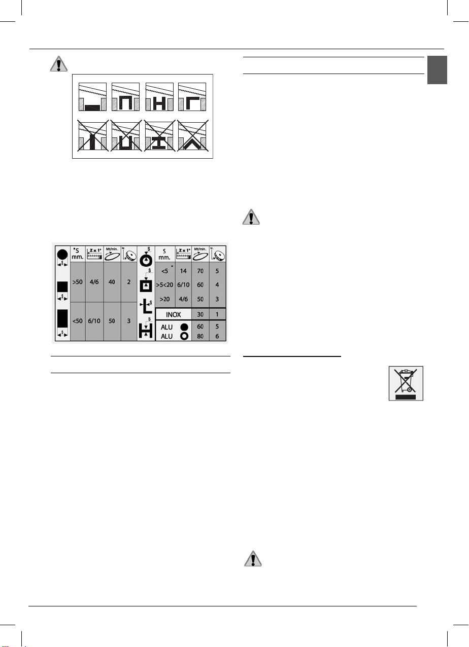
La tabella di seguito riportata specifica le capacità di taglio
a 0°, 45° gradi ottenibili nelle normali condizioni di utilizzo
descritte in questo manuale,e senza interposizione di alcun
oggetto fra le ganasce della morsa.
0° = Ø 150 mm; 150 mm; 160x140 mm
45° = Ø 100 mm; 100 mm; 120x100 mm
4.5 USO DELLA MORSA (Fig. 1)
La morsa della segatrice è dotata di scorrimento rapido, al
fine di permettere l’avvicinamento del corsoio al pezzo da
bloccare in modo pratico e veloce.
Per bloccare il pezzo da tagliare in morsa:
• disponetevi di fronte alla macchina;
• azionate la leva 3verso il pezzo da tagliare, sbloccando
il corsoio 11;
• spingete il corsoio verso il pezzo da tagliare, avvicinan-
dolo fino a qualche millimetro da esso;
• bloccate la leva 3, spingendola verso di voi;
• ruotate la leva 12 in senso orario, bloccando definitiva-
mente il pezzo tra le ganasce.
Se dovete tagliare più pezzi dalla stessa barra, è sufficiente
sbloccare e successivamente ribloccare la morsa tramite
la leva 12.
Se invece dovete cambiare barra, prima sbloccate la morsa
ruotando in senso antiorario la leva 12 e successivamente
azionate la leva 3 allontanando il corsoio dal pezzo.
4.6 POSIZIONAMENTO CORRETTO DEL PEZZO IN
MORSA (Fig.11)
Ipezzi datagliarevanno inseritidirettamente fraleganasce,
senza interposizione di altri oggetti.
4 UTILIZZAZIONE
4.1 RODAGGIO DELLA LAMA
ATTENZIONE: Non effettuare una corretta
procedura di rodaggio significa compromettere
irrimediabilmente la precisione di taglio della
lama.
Per ottenere le migliori prestazioni, le lame bimetalliche che
corredano la vostra segatrice devono essere sottoposte ad
una breve procedura di rodaggio.
Occorre perciò effettuare i primi dueo tre tagli possibilmente
suun pezzopienoØ 40- 50mm.,esercitando sulpezzo una
pressione molto lieve, incrementandola man mano nei tagli
successivi.Perrendervi contodi qualesia lapressione giusta
nellenormali condizionidi utilizzodefiniteda questomanuale
(vedi TABELLA DI TAGLIO), considerate ad esempio che il
primo taglio su un acciaio (es. C40) pieno Ø 50 mm . deve
essere effettuato in circa 4 minuti; a rodaggio ultimato, lo
stesso pezzo può essere tagliato tranquillamente in circa
2 minuti. Un rodaggio ben eseguito, comporta una migliore
qualità del taglio, sia come finitura che come precisione, ed
una maggiore durata della lama.
4.2 FUNZIONAMENTO (Fig. 7)
Commutate l’interruttore generale D sulla posizione 1: in
questomodo l’interruttoresi accende,e lamacchina èpronta
per funzionare.
ATTENZIONE: Prima di iniziare ogni operazione
di taglio, accertatevi mediante un controllo a
vista che tutte le protezioni siano integre ed in
posizione adeguata.
Una volta eseguite tutte le procedure e le operazioni fin qui
descritte, potete iniziare le lavorazioni.
Pereffettuareiltaglio,disponetevidi frontealla macchina,ed
impugnate con la mano destra l’impugnatura.
ATTENZIONE: Tenete la mano sinistra sempre
lontana dalla zonadi taglio enon cercate in alcun
modo di raggiungerla durante le operazioni di
taglio.
Premetecon l’indicedellamanodestrailpulsantedi marciaA
(Fig. 4) edabbassategradualmente il corpo fino a metterea
contatto dolcemente la lama con il pezzo da tagliare.
Iniziate ora ad applicare uno sforzo progressivo sul pezzo,
e completate il taglio.
ATTENZIONE: Fra un taglioed un altro,nella fase
di posizionomento del pezzo,rilasciate sempre il
pulsanteA, noncercate dibloccarlo o dialterarne
in alcun modo le caratteristiche funzionali.
Se doponumerosi tagliconsecutivi lamacchina dovesse
improvvisamente fermarsi,non allarmatevi:èintervenuto
il termoprotettore del motore, che toglie l’alimentazione
quando la temperatura degli avvolgimenti raggiunge la
soglia limitedefinita dalla classedi isolamento,evitando
danni al motore.
In questo caso, rilasciate il pulsante A ed attendete il
ripristino automatico,che ritornain generedopo qualche
minuto. Ilregolatore elettronicodi velocitàdi cuila vostra
segatrice è dotata include la funzione di protezione del
motore, ottenuta tramite un limitatore amperometrico
che non gliconsente diassorbire unacorrente maggiore
di quella impostata, espressa dal valore massimo di
assorbimento programmato (vedi 2.5).

5
IT
ATTENZIONE: Non tenete mai i pezzi da tagliare
in mano. 6 MANUTENZIONE
6.1 INTERVENTI DI MANUTENZIONE ORDINARIA
Le normali operazioni di manutenzione ordinaria, effettuabili
anche da personale non specializzato, sono tutte descritte
nei paragrafiprecedenti e nel presente.
1. Prima di effettuare qualsiasi operazione di manuten-
zione, disinserite la spina elettrica della macchina dalla
presa di corrente.
2. Durante le operazioni di manutenzione, indossate sem-
pre, per quanto possibile,i mezzi personali di protezione
(occhiali antinfortunistici e guanti di dimensioni adatte).
3. Rimuovete i trucioli residui di lavorazione ogni qualvolta
si renda necessario, intervenendo nella zona di taglio e
sui guidalama.
È consigliato l’uso di un pennello o di un aspiratore.
ATTENZIONE: Non usate getti di aria
compressa.
4. Se non utilizzate la segatrice per lungo tempo, ripulitela
e mettetela possibilimente in un luogo privo di umidità.
È buona norma, in questi casi, allentare la lama per non
mantenerla inutilmente in tensione.
6.2 ASSISTENZA
Nel caso sia necessario l’intervento di personale qualificato
peroperazionidi manutenzionestraordinaria,oppure nelcaso
diriparazioni sia inregime digaranziachesuccessivamente,
rivolgetevi sempre ad un Centro di Assistenza autorizzato,
oppure direttamente alla fabbrica, se nella vostra regione
non è presente il Centro di Assistenza.
6.3 SMALTIMENTO MACCHINA, IMBALLAGGIO
INFORMAZIONE AGLI UTENTI
Ai sensi dell’art. 13 del Decreto Legislativo 25
luglio 2005, n. 151 “Attuazione delle Direttive
2002/95/CE,2002/96/CEe2003/108/CE,relative
alla riduzione dell’uso di sostanze pericolose
nelle apparecchiature elettriche ed elettroniche,
nonché allo smaltimento dei rifiuti”, si precisa
quanto segue:
• Il simbolo del cassonetto barrato riportato sull’apparec-
chiatura o sulla confezione indica che il prodotto alla fine
della propria vita utile deve essere raccolto separatamen-
te dagli altri rifiuti.
• L’utente dovrà, pertanto conferire l’apparecchiatura
giunta a fine vita agli idonei centri di raccolta differen-
ziata dei rifiuti elettronici ed elettrotecnici, oppure ricon-
segnarla al rivenditore al momento dell’acquisto di una
nuova apparecchiatura di tipo equivalente, in ragione di
uno a uno.
• L’adeguata raccolta differenziata per l’avvio successivo
dell’apparecchiatura dismessa al riciclaggio, al tratta-
mento e allo smaltimento ambientalmente compatibile
contribuisce ad evitare possibili effetti negativi sull’am-
biente e sulla salute e favorisce il reimpiego e/o riciclo
dei materiali di cui è composta l’apparecchiatura.
ATTENZIONE: Lo smaltimento abusivo
del prodotto da parte dell’utente comporta
l’applicazione delle sanzioni amministrative
previste dalla normativa vigente.
Fig. 11
Quandoil taglioriguarda iprofilati,piattiosagomeparticolari,
fare riferimento agli esempi di figura.
Selo spessoredel profilatodovesse esseremolto sottile,per
evitare il suo schiacciamento tra le ganasce della morsa, è
meglio inserire all’interno del profilato stesso una sagoma
che ne copi il profilo.
4.7 TABELLA DI TAGLIO
5 ACCESSORI
5.1 SCELTA DELLA LAMA
Lavostra segatriceècorredatadi lamabimetallicamm.1735
x 13 x0,9 con dentatura variabile 6/10 denti per pollice, che
copre gran parte dei tagli possibili con questa macchina.
Per le esigenze particolari (vedi Tabella di taglio 4.7), ad
esempioperiltagliodi grossesezionipieneoppuredi profilati
o angolari di piccolo spessore, sono disponibili anche lame
con dentatura 4/6 oppure denti per pollice.
MATERIALE:............m42 (acciaio per molle ÷ acciaio
HSS)
SVILUPPO:..........................................................mm 1735
ALTEZZA:.................................................................mm 13
SPESSORE:...........................................................mm 0,9
DENTATURA:................................................standard 6/10
....................................................................optional 4/6 -14
5.2 MONTAGGIO DEL BASAMENTO (dove
previsto) (Fig. 3)
Per fissare la macchina sul basamento occorre utilizzare le
quattro viti a brugolaA, i quattro dadi B e le quattro rondelle
C fornite in dotazione con il basamento stesso.
Inserite le viti a brugola nei fori presenti sulla base, e
bloccatele all’interno del basamento con le rondelle ed i
dadi.

6
IT
Motore, cavo rete o spina difettosi.
Fusibili quadro elettrico bruciati.
Manca tensione nell’impianto di
rete.
È intervenuto il termoprotettore
del motore.
Surriscaldamento del motore.
Sovraccaricodel motorecausatoda
eccessiva pressione di taglio.
Guasto del motore.
La taratura dei fermi H e K (punto
3.3) non è esatta.
Pressione di taglio eccessiva (su
tubi e profilati).
Dentaturadella lamanon correttain
relazione al pezzo da tagliare.
Velocità di taglio non corretta in
relazione al pezzo da tagliare.
Regolazione non corretta dei
guidalama eccentrici e scorrevole.
Errato posizionamento del pezzo
in morsa.
La lama è consumata oppura non
ha dentatura adatta allo spessore
del pezzo che state tagliando.
Eccessiva pressione di taglio.
Regolazione non corretta dei
guidalama eccentrici.
Eccessivo consumo della
gommatura delle pulegge.
Slittamentodellalamasullepulegge,
causatodapresenzadiolioegrasso
per il taglio.
Il motore non funziona.
Intervento
del termoprotettore.
Imprecisione dell’angolo
di taglio a 90°-45°.
Imprecisione nello
squadro del taglio.
La finitura del taglio
risulta grezza o
ondulata.
La lama tende ad uscire
dalle guide.
Fatecontrollarelamacchinadapersonalespecializzato;
non tentate di riparare il motore da soli.
Controllate l’integrità dei fusibili e sostituiteli se
necessario.
Controllate la presenza di tensione nell’impianto di
rete.
Attendete il normale ripristino del termoprotettore
(alcuni minuti) rilasciando il pulsante di marcia.
Controllate che le prese di aereazione del motore
siano libere da ostacoli.
Eseguite il taglio con la giusta pressione sul pezzo.
Fatecontrollarelamacchinadapersonalespecializzato;
non tentate di riparare il motore da soli.
Effettuate la taratura allentando le viti di fissaggio e
riposizionando i fermi.
Diminuite la pressione di taglio.
Controllate i parametri di taglio (dentatura della lama,
velocità di taglio) nella tabella di taglio (punto 4.7).
Controllate la regolazione dei guidalama (punti 3.5
e 3.6).
Controllateil posizionamentoed ilserraggio delpezzo
nella morsa (punto 4.5).
Controllate i parametri di taglio (dentatura della lama,
velocità di taglio) nella tabella di taglio (punto 4.7).
Diminuite la pressione di taglio.
Controllate la regolazione dei guidalama eccentrici
(punto 3.6).
Fate controllare ed eventualmente sostituire le
pulegge da personale specializzato.
Non utilizzate assolutamente alcun lubrificante
o refrigerante per il taglio; fate controllare ed
eventualmente sostituire le pulegge da personale
specializzato.
PROBLEMA PROBABILE CAUSA RIMEDIO SUGGERITO
7 GUIDA ALLA LOCALIZZAZIONE DEI GUASTI

EN
7
Fig. 12
1.4 RECOMMENDED AND NOT RECOMMENDED
USAGE
This belt sawing machine was designed and constructed
according to the most advanced technologies and may be
used for all cutting requirements for metals commonly used
in industry and artisanship.
It can cut:
- COMMON STEELS (FE 37...)
- SPECIAL STEELS (C 40, 18NiCrMo5...)
- ALUMINIUM AND ITS ALLOYS
- BRASS
- BRONZE
- STEEL TUBING (FE 35, FE 52...)
- PROFILED SECTIONS IN SHEET METAL AND ALU-
MINIUM
It is not suitable for cutting:
- WOOD AND SIMILAR MATERIALS
- BONE AND SIMILAR MATERIALS
ATTENTION: The band saw has been developed
and manufactured to cut in dry condition; the
use of any cooler by lubricating oil makes the
machine unusable.
1.5 STANDARD SAFETY PROCEDURS
- Do not use the machine in very damp places or in the
presence of inflammable liquids or gases.
- Do not use it in the open air when general weather and
environmental conditions are unfavourable (eg. explosive
atmospheres, during a storm or rain).
1 INTRODUCTION TO USE
Before starting work with your sawing machine, carefully
read this instructions manual so that you are familiar with
the machine and its uses and where it should not be used.
Keep this manual in a safe place. It is an integral part of the
machine and should be used for reference in operating the
machine correctly and in the proper safety conditions.
Use the machine only and exclusively for the uses specified
below, asrecommended inthis manual.Themachineshould
not in any way be tampered with, or forced, or used for
unsuitable purposes.
1.1 SYMBOLS PLACED IN CORRESPONDANCE
WITH USAGE POINTS
Neverunderestimatethewarnings“ATTENTION -CAUTION”
given in this manual.
In order to draw the user’s attention and to preserve safety,
hazardousoperation areprecededbysymbolsand notesthat
point out the dangerand explain how to behaveto avoid any
risk.Thesesymbols andnotesare dividedinthreecategories,
identified by the following words:
ATTENTION: dangerous-behaviours that could
cause serious injuries.
CAUTION: behaviours that could cause slight
injuries or damages to things.
NOTE: the notes preceded by this symbols are
technical and are aimed at making operations
easier.
1.2 SAFETY AND RULES
The machine was designed and built according to the
Community Directives in force: EC/2006/42 - EC/2004/108
- EC/2006/95.
Theenclosed CEDeclaration ofconformity, togheterwiththe
CEmark onproduct, essentiallycomprise andare anintegral
part of the machine: both guarantee product conformitywith
the aforesaid safety Directives.
1.3 SAFETY PLATES/LABELS
The safety plates/labels and indicators present on the
machine, the location of which is shown in the Figure 12,
are as follows:
- Wear noise protection devices.
- Wear safety masks or goggles.
- Do not insert the hands in this area with
the tool operating. Danger of dragging/
cutting.
INDEX
1 INTRODUCTION TO USE.........................................7
2 INSTALLATION .........................................................8
3 ADJUSTING (Fig. 4-5-6-7-8-9)..................................9
4 USE ...........................................................................9
5 ACCESSORIES....................................................... 11
6 MAINTENANCE....................................................... 11
7 TROUBLESHOOTING.............................................12 Matr. n. ...........

EN
8
- Wearsuitableclothes, withoutwide sleevesor articlessuch
as scarves, chains and bracelets which could get caught
in the moving parts.
- Alwaysuse personalprotectiondevices:protectivegoggles
as recommended by safety standards, gloves of the right
size, headphones or earplugs, and hairnets if necessary.
- Use the tools recommended in this manual if you want
to achieve the best performance from your sawing
machine.
- Any power cable extensions must be type approved and
comply with safety standards.
- Avoid using the machine if your psycho-physical condition
are precarious or upset.
1.6 SAFETY PROCEDURS FOR FURTHER RISK
- Always keep processing residues away from the cutting
area.
- Always use the clamp. The parts to be cut must always be
held firmly in the clamp.
- Alwayskeep handsawayfrom theworking areaswhilethe
machine is moving: before loading or unloading the part,
release the run button on the hand grip.
- Do not force the machine unnecessarily : excessive
cutting pressure could cause rapid wear to the blade and
negatively influence the performance of the machine in
terms of finishes and cutting precision.
1.7 INFORMATION REGARDING NOISE AND
VIBRATIONS
Noise
Noise level at the operator’s work
position (without load).............................. Leq 81.5 dB (A)
Noise level at the operator’s work position (with load)
Cutting of 80 mm dia. barstock in 9SMnPb28 steel at speed
of 80 m/min ................................................Leq 82.4 dB(A)
Cutting of 60x60 steel profile with 3 mm wall thickness at
speed of 80 m/min. ....................................Leq 85.6 dB(A)
Test conditions
Sound power (without load)......................Lwa 93.4 dB (A)
Sound power (with load)
Cutting of 80 mm dia. barstock in 9SMnPb28 steel at speed
of 80 m/min .............................................Lwa 94.2 dB (A)
Cutting of 60x60 steel profile with 3 mm wall thickness at
speed of 80 m/min. ...................................Lwa 96.7 dB (A)
The measurements were carried out in accordance with
standard UNI EN ISO 3746.
Vibration
Mean frequency-weighted hand - arm acceleration vibration
exposure does not exceed 2.5 m/s².
The measurements were carried out in accordance with
standards UNI EN ISO 5349-1 and 5349-2.
The emission levels indicated are not necessarily safety
levels.Although thereis arelationshipbetweentheemissions
and exposure levels, the values shown cannot be used for
establishingthe needfor furtherprecautions.Thereare other
factorswhichinfluencetheexposurelevelsofoperators, such
as the features of the work place, presence of other sources
of noise, number of machines running, etc.
The exposure levels may also vary between countries.
Thisinformationisnecessaryfortheuser forbetterevaluation
of the risks and hazards deriving from noise.
NOTE: Personal hearing protection should be
used, such as headphones or earplugs.
1.8 INFORMATION ABOUT THE
ELECTROMAGNETIC COMPATIBILITY
The European regulations on safety and, in particular, the
Directive2004/108/CE contemplatethat allthe equipmentbe
equipped with shielding devices against radio interferences
both from and towards the outside.
This machine is equipped with filters through which the
machine is safe and in compliance with above regulations.
Testswere carriedout accordingto 61000-6-1,EN 61000-
6-3, EN 55014-1, EN 55014-2 regulations.
1.9 DESCRIPTION OF THE MACHINE (Fig. 1)
The belt sawing machine consists of two basic parts: the
machine body 5complete with motor and drive 7which is
integrated into lower part, consisting of the clamp 11, the
base 13 and swivel support 9.
Here is a list of the main parts with the number indicating it
in the drawing.
Legend Fig. 1
1Grip
2Blade tension handwheel
3 Vice speed-slide drive
4Sliding blade guide
5Machine body
6Blade
7Motor
8Control box
9Bar stop
10 Clamp (vice)
11 Morsa
12 Clamp drive
13 Base
14 Handle for handling
WEIGHT ..................................................................35 Kg.
SIZE ........................................................ cm 108 x75xH80
.........................................in maximum overall dimensions.
PACKAGING SIZE ............................. cm 100 x 39 x H57
2 INSTALLATION
2.1 REMOVING THE PACKING
Remove the wooden frame which protects the machine
during transit.
Try not to damage the frame as you may have to move the
machine long distances or store it for long periods.
2.2 HANDLING (Fig. 2)
As the machine is considerably heavy (35 kg net), it needs
at least 2 people to lift it, positioned on either side.
The machine must be lifted and transported by the handle
14 fixed on the base plate.
2.3 TRANSPORT (Fig. 2)
Before moving the machine from one place to another by
lifting it, apply the two handles 14 attached to the base.
Take the handles and fix them with the screws and the nuts
on both sides of the base of machine.
It is necessary to low the saw body till the lower position and
fix it to the base; then you can proceed with the trasport by
lifting the machine by two person moving it at the handle.
Shouldthe machinebe fixedonabaseplate(column)unlock
the screws first.

EN
9
Fortrasportthe machine,it is betterto place inthe boxitwas
when purchased. Ensure it is placed in the correct position
indicated by the arrows on the packaging.
Pay careful attention to the ideogram printed on the box as
they provide all necessary information for palletization and
stacking af boxes.
Tyingtheloaddown withropesor safetybeltsisraccomended
during trasportation to prevent the load from sliding or
falling.
2.4 POSITION/WORK STATION (Fig. 3)
Placethe machineon asufficientlyflatworkbenchso thatthe
machine has the better possible stability. Should you wish
to fix the machine in place, use the special holes located
on the base.
In respect of ergonomic criteria during cutting operations,
the workbench must be positioned at such a height that
the clamp level is between 90 and 95 cm from the ground
(see fig. 3).
ATTENTION: Makesure thatthemachine isplaced
in a working area with suitable environmental
conditions and lighting. The general conditions
of the working environment are of fundamental
importance for accident prevention.
2.5 ELECTRICAL CONNECTIONS
Check that the mains to which the machine is connected is
earthed in accordance with current safety regulations and
that the power point is in good condition.
Rememberthat thereshould beamagnetothermicprotective
device fitted upstream of the mains to protect all the
conductors from short circuits and overloads.
This protective device should be selected according to the
electrical features of the machine listed below:
Nominal voltage..................................................230 Volt ~
Nominal frequency........................................... 50/60 Hertz
Max programmed absorbed value......................2000 Watt
Nominal input power...........................................1200 Watt
Power factor.................................................................0,96
Nominal speed......................................11.000-23.000 rpm
Insulation...............................................................Classe F
Type of service...................................intermittent S4-60 %
In caseof powerfailure inmains, whileyouwait forpower
to be restored there is no danger hazard may arise: in
fact, the electronic governor O (Fig. 7) is also equipped
with a reset function which prevents the machine from
restarting automatically.
The motor of your sawing machine is equipped with
a protective heat circuit breaker which interrupts the
power supply when the temperature of the coils rises
too high.
When the power supply is interrupted, wait for normal
reset.
3 ADJUSTING (Fig. 4-5-6-7-8-9)
3.1 TENSION OF THE BLADE (Fig.4)
ATTENTION: The machine is fitted with a
blade-tightening device that limits tension
automatically.
Turn handwheel Bclockwise until the clutch engages
3.2 BAR STOP (Fig. 5)
Use the bar stop supplied if you have to do several cuts on
pieces of the same length.
Inthis wayyoudonothaveto repeatthe samemeasurement
each time.
Screw rod E into the hole of the base and fasten it with nut F.
Slackenthe handwheelGand placethestopLatthe correct
distance from the blade. Tighten handwheel Gagain.
3.3 CUTTING ANGLE (Fig. 6)
To performe a cut at 45, slacken the two knobs Mand rotate
the body to the left until it rest on stop N, whose position was
calibrated during the final inspection.
For all the other intermediate angles, match the indicator
of the swivel supporto with the respective position on the
plate O.
3.4 CUTTING SPEED (Fig. 7)
Your sawing machine is equipped with CESC (Constant
Electronic Speed Control), which allows gradual and
continuous variation of the cutting speed, adapting it to the
type and dimension of the material to be cut (see CUTTING
TABLE ).
Toselectthemost suitablespeed, usethespeedcontrolknob
O to increase or decrease the speed as you require.
3.5 SLIDING BLADE GUIDE (Fig. 8)
Thesliding bladesguide Pwithintegrated protectionfittedon
yoursawing machineis usedtoperformthecutwhileguiding
the necessary part of the blade and fully protecting the part
not used in the cutting process.
Slacken the knobs Qand slide the blades guide Pso as to
move it closer to or further from the part to be cut.
ATTENTION: If this adjustment is not done, the
part of the blade not used in the cutting process
will beexposed andthis will createan extrarisk of
contact, besides altering the quality of the cut.
3.6 BEARINGS BLADE GUIDE (Fig.9)
The blade-guide on the outside of the sawing machine are
eccentricand adjustablesoas tosimplify bladereplacement
and to keep it guided as its best.
Theymust alwaystouchthebladeslightly, sothat theyrotate
when the blade passes, but must not be completly locked.
In order to approach or remove the eccentric blade-guide,
gently turn the head of the screws R using a 10 mm.
wrenches key.

EN
10
4 USE
4.1 RUNNING IN THE BLADE
ATTENTION: If the correct running in procedure
is not performed, the bladès cutting precision
may be irreparably compromised.
To obtain thebestperformance, the bi-metalbladesfittedon
your sawing machine must be run in for a short period.
For this reason the first two or three cuts should be done
where possible on a solid piece Ø 40-50 mm, using a very
slight pressure on the blade, and gradually increasing
pressure in subsequent cuts.
Togaugethe correctpressure innormal operatingconditions
defined by this manual (see cutting table), consider for
example that the first cut on solid steel (eg. C40) Ø 50 mm
should be done in about 4 minutes.
After running-in, the same piece may easily be cut in about
2 minutes. If the running-in process is done correctly, the
finish and precision of the cut will be of better quality and
the blade will last longer.
4.2 WORKING (Fig. 7)
Turn the main switch D to position 1 : in doing the switch
comes on and the machine is ready for operation.
ATTENTION: Before starting any cutting
operation, check that all the protections are
complete and in the correct position.
Onceyou havecompletedalltheprocedures andoperations
described so far, you may start the working processes.
To perform the cut, move tothe front of the machineand grip
the handgrip with your right hand.
ATTENTION: Keep your left hand away from the
cutting area and on no account try to reach it
when cutting is in process.
Useyour right-handforefingertopress startbuttonA (Fig.4)
and lower the body gradually until the blade lightly touches
the work piece to be cut.
Now begin to apply gradual pressure on the part and
complete the cut.
ATTENTION: Always release button A between
one cutting operation and another, while you are
positioning the part. do not try to block it or alter
its functional characteristics in any way.
If the machine suddenly stops after numerous
consecutive cuts, do notbe alarmed. The heatprotector
device of the motor has been activated, breaking the
power supply whenthe temperature of thecoils reaches
the threshold limit defined by the insulation class, to
prevent damage to the motor.
In this case, release the buttonA and wait for automatic
reset which usually takes place after a few minutes.
Your sawing machine is equipped with an electronic
speed governor which also includes a motor protection
function obtained by means of an amperometric limiter.
In thisway it cannot absorban amountof currentgreater
than the set one, expressed by the maximum value of
absorption (see 2.5).
If the limiter trips while the machine is in operation,
slightly decrease the cutting pressure in addition, this
enables to safeguardthe blade lifeand performance and
to obtain always a sharp and clean cut.
4.3 REPLACING THE BLADE
CAUTION: When you perform this operation,
always wear protective gloves to avoid contact
with the teeth of the blade.
- check that the main switch D (Fig. 7) is at position 0;
- slacken the handles Q and slide the blades guide P as far
as it will go, following the direction on the arrow (Fig. 8);
- remove the protective casing unscrewing the four
screws;
- slacken the blade tension, turning the handwheel B in a
anti-clockwise direction (Fig. 4);
- extract the blade first from the guides and then from the
rubber coated pulleys;
- insert the new blade first between the guides and then
onto the rubber coated pulleys, with the teeth facing as
showed in (Fig. 9);
- put the blade under tension again as described in point
3.1.
- replace the protective casing;
- reposition the blade guides P in the correct position for the
next cut.
ATTENTION: This machine has been developed
for working with the blade rotating clockwise
(Fig. 9). It is absolutely necessary to check that
the blade is produced according to this rotation
mode.
4.4 CUTTING CAPACITY (Fig.10)
The table below specifies the cutting capacity at 0, 45
degrees which may be obtained in normal conditions of use
describedin thismanual andwithout placingany otherobject
between the jaws of the clamp.
0° = Ø 150 mm; 150 mm 160x140 mm
45° = Ø 100 mm; 100 mm 120x100 mm
4.5 USING THE VICE (Fig. 1)
The chuck of the saw is of the quick sliding type so that
the slider easily and rapidly approaches the pieces to be
locked.
To lock the piece to be cut in the chuck:
• place yourself in front of the machine;
• release the lever 3 towards the piece to be cut by unlo-
cking vice part 11.
• position the slider at a few millimetres from the piece to
be cut;
• move the 3towards the piece and lock it;
• turn lever 12 clockwise so as to definitely lock the piece
between the jaws.
If more pieces of the same bar are to be cut, you only need
to unlock and then re-lock the chuck by means of lever 12.
If you need, instead, to change the bar, turn the lever 12
counterclockwise to unlock the chuck and then pull lever 3
towards you so that the slider moves away from the piece.
4.6 CORRECT POSITIONING OF THE PIECE IN THE
CLAMP (Fig. 11)
The pieces to be cut should be fitted directly between the
jaws without adding other objects.

EN
11
6 MAINTENANCE
6.1 REGULAR MAINTENANCE
The operations of ordinary maintenance, which may also be
performed by non-specialist personnel, are all described in
the previous sections and here below.
1. Beforeperforminganymaintenanceoperation,disconnect
the machine electric plug from the wall outlet.
2. During maintenance operations, always wear personal
protection (safety goggles and gloves).
3. Remove the processing residues from the cutting area
and the blade guides whenever necessary.
You are advised to use a suction device or a brush.
ATTENTION: Do not use jets of compressed air.
If you do not intend to use the sawing machine for a long
time, clean it and put it in a dry place if possible.
In these cases it is advisable to slacken off the blade so that
it is not kept tight for no reason.
6.2 ASSISTENCE
Should it be necessary to call qualified personnel for
operations of extraordinary maintenance, or in the case of
repairs,under guaranteeor ata laterdate,youshouldalways
contact an authorized service centre or the factory directly, if
there is no service centre in your area.
6.3 DISPOSAL OF THE MACHINE AND PACKAGING
NFORMATION FOR USERS
Inaccordance withart. 13of LegislativeDecree
25th July 2005, no. 151 “Implementation
of Directives 2002/95/EEC, 2002/96/EEC
and 2003/108/EEC, relative to reducing the
use of hazardous substances in electrical and electronic
appliances and the disposal of waste”, please take note of
the following:
• The crossed out wheelie bin symbol found on the ap-
pliance or on the packaging, indicates that the product
must be disposed of separately from ordinary house-
hold waste when it reaches the end of its working life.
• The user must consign the unwanted appliance to an
authorized differentiated waste disposal centre for elec-
trical and electronic goods, or alternatively, hand it over
to the relative dealer on purchasing a new appliance of
the same type on the basis of a one to one ratio.
• Differentiated disposal, to enable possible recycling or
environmentally compatible elimination of the applian-
ce, helps to limit undesirable effects on health and the
environment and promotes the reuse and/or recycling of
the materials which went into making up the appliance.
WARNING: Sanctions, in accordance with the
relative legislation in force in the country of use,
will be imposed on the user if the appliance is
disposed
ATTENTION: Never hold the pieces to be cut in
your hand.
Fig. 11
Whenthe piecestobecutare profiledsections,flatpiecesor
special shapes, refer to the examples shown in the figures.
If the thickness of the profiled section is to be very thin, an
outline should be fitted which copies the profile inside the
profiled section itself to stop it being crushed between the
jaws.
4.7 CUTTING TABLE
5 ACCESSORIES
5.1 CHOISE OF BLADE
Your sawing machine is equipped with a bi-metal blade
measuring 1735x13x0,9 mm with variable toothing 6/10
teethper inch,for useinthemajorityofcutspossible withthis
machine. For special requirements (see cutting table point
4.7), for example, for cutting large solid sections or profiled
sections or corner pieces of small thickness, there are also
blades avail-able with 4/6 toothing or 14 teeth per inch.
MATERIAL: ................M42 (steel for springs ÷ steel HSS)
EXTENSION:.......................................................mm 1735
HEIGHT:...................................................................mm 13
THICKNESS:...........................................................mm 0,9
TOOTHING:..................................................standard 6/10
...................................................................optional 4/6 - 14
5.2 FITTING THE BASE PLATE (Fig. 3)
(where included)
Thefasten the machineto thebaseplate, usethe four screw
A, four nuts B and four Washer Cconteined in yhe carton
box of the base plate.
Put the four screws Ainto the holes of the base of the
machine, and fasten the whole with the four nuts B.

EN
12
Defective motor, power cable or
plug.
Blown electric panel fuses.
No voltage in the mains system.
The overload cutout has tripped.
Motor overheating.
Motoroverloadcausedbyexcessive
cutting pressure.
Motor breakdown.
The setting of the H and K retainers
(point 3.3) is inaccurate.
Excessive cutting pressure (on
pipes and section bars).
Incorrect blade toothing in relation
to the piece to cut.
Incorrectadjustmentoftheeccentric
and sliding blade-guides.
Incorrectcutting speedinrelation to
the piece to cut.
The piece is wrongly positioned
in the vice.
The blade is worn or its toothing
is not right for the thickness of the
piece being cut.
Excessive cutting pressure.
Incorrect eccentric blade-guide
adjustment.
Excessivewear ofthepulley rubber
linings.
The blade slips on the pulleys,
caused by oil or grease required for
cutting operations.
The motor does not
work.
Overload cutout
tripped.
Inaccurate cutting angle
at 90° - 45°.
Inaccurate cut
squaring.
Cut finish is coarse or
corrugated.
The blade tends to
protrude from
the guides.
Specialized personnel should check the machine; do
not attempt to repair the motor by yourself.
Check fuse integrity and replace, if necessary.
Check for voltage in the mains system.
Release the run button and wait a few minutes for the
overload cutout to reset.
Check that motor air intakes are clear.
Perform the cut on the piece at the correct pressure.
Specialized personnel should check the machine; do
not attempt to repair the machine by yourself.
Setthe retainersbyunloosening thefastening screws
and re-positioning them.
Decrease cutting pressure.
Check the cutting parameters (blade toothing, cutting
speed) in the cuts table (point 4.7).
Check blade-guide adjustment (points 3.5 and 3.6).
Check piece positioning and clamping in the vice
(point 4.5).
Check the cutting parameters (blade toothing, cutting
speed) in the cuts table (point 4.7).
Decrease cutting pressure.
Check eccentric blade-guide adjustment (point 3.6).
Specialized personnel should check the pulleys and
replace them if necessary.
Never use any type of lubricant or coolant for the
cuttingoperations;specializedpersonnelshould check
and, if necessary, replace the pulleys.
PROBLEMS PROBLEMS CAUSES SOLUTIONS SUGGESTED
7 TROUBLESHOOTING

DE
13
Abb. 12
1.4 EINSATZGEBIET UND UNGEEIGNETER
EINSATZ
Die Bandsägemaschine wurde unter Einsatz neuester
Technologie entwickelt und realisiert.
SiebefriedigtalleAnforderungendestypischenMetallsägens
in Industrie- u. Handwerksbereich.
Geeignet zum Sägen von:
- NORMALSTAHL (FE 37...)
- SPEZIALSTAHL (C 40, 18NiCrMo5...)
- ALUMINIUM UND ALU-LEGIERUNGEN
- MESSING
- BRONZE
- STAHLRÖHRE (FE 35, FE 52...)
- BLECH- UND ALUMINIUMPROFILE
Nicht geeignet zum Sägen von:
- HOLZ UND ÄHNLICHE MATERIALEN
- KNOCHEN UND ÄHNLICHE MATERIALEN
ACHTUNG: Die Bandsägemaschine wurde zum
Trockenschneiden konzipiert und gebaut. Durch
die Verwendung eines Schmier-/Kühlmittels wird
die Maschine untauglich.
1.5 ALLGEMEINE SICHERHEITSVORSCHRIFTEN
- Gebrauchen Sie die Maschine nicht in feuchten Räu-
men, in der Nähe von explosiven Substanzen oder
Gas.
- Arbeiten Sie nicht im Freien wenn die Wetterbedingun-
gen es nicht zulassen (Niederschlag, Gewitter), oder
wenn explosive Substanzen in der Nähe oder in der
Atmosphäre sind.
- Achten Sie auf geeignete Arbeitskleidung: vermeiden
Sie weite Ärmel sowie Kleidungsstucke, die sich in den
beweglichen Maschinenteilen verfangen könnten.
- Verwenden Sie stets persönliche Sicherheitshilfsmittel:
normentsprechende Sicherheitsbrillen, Handschuhe
die Ihrer Handgrösse entsprechen, Ohrschutz und Ha-
arnetze bei Bedarf.
1 EINFÜHRUNG
Lesen Sie die Gebrauchsanweisung aufmerksam durch,
bevor Sie mit Ihrer Bandsäge zu arbeiten beginnen und
lernen Sie die Maschine, ihren Einsatz und Grenzen genau
kennen. Bewahren Sie dieses Heft sorgfältig auf: es ist
als Bestandteil der Maschine zu betrachten, und muss Ihr
Referenzpunktsein,umamBestenundinhöchsterSicherheit
alle nachfolgend beschriebene Arbeiten durchzuführen.
Setzen Sie die Maschine nur für die folgend beschriebenen
und empfohlenen Arbeiten ein, ohne sie zu forcieren,
abzuändern oder sie zweckfremd zu gebrauchen.
1.1 SYMBOLE UND KENNZEICHEN
Bitte dieAnweisungen “ACHTUNG - VORSICHT - MERKE”
im Handbuch nicht unterschätzen.
Um Ihre Aufmerksamkeit zu wecken und um
Sicherheitshinweise zu geben, erscheinen bei gefährlichen
Arbeitssituationen Symbole und Anmerkungen, die das
RisikobeiderArbeithervorhebenund zugleicherklären, wie
man sich zu verhalten hat, um Gefahren zu vermeiden.
Es handelt sich um drei Symbole, die durch folgende Worte
gekennzeichnet sind:
ACHTUNG: gefährliches Verhalten, das zu
schweren Verletzungen führen kann.
VORSICHT: Verhalten, das zu Verletzungen oder
Schäden an Gegenständen führen.
MERKE : Technische Ratschläge, die die
Arbeitsweise erleichtern können.
1.2 SICHERHEIT UND NORMEN
Die Maschine wurde so konzipiert und gebaut, dass sie
den Anforderungen der gültigen EG Richtlinien entspricht:
2006/42/EG - 2004/108/EG - 2006/95/EG.
Die beiliegende EG Konformitätserklärung, zusammen mit
dem auf dem Produkt angebrachten „CE“ Kennzeichen, ist
ein grundlegendes Element und ein wesentlicher Teil der
Maschine: Sie ist die Garantie, dass das Produkt den o. g.
Sicherheitsrichtlinien entspricht.
1.3 SICHERHEITSSCHILDER/-AUFKLEBER
An der Maschine sind folgende Sicherheits- und
Hinweisschilder/-Aufkleber in der Postion gemäßAbbildung
12 angebracht:
- Gehörschutz benutzen
- Gesichts- oder Augenschutz benutzen.
- Einführen der Hände in diesen Bereich
verboten, Werkzeuge sind in Betrieb. Ein-
zugs-/Schnitt.
INHALT
1 EINFÜHRUNG.........................................................13
2 INSTALLIEREN .......................................................14
3 EINSTELLUNG (Abb. 4-5-6-7-8-9)..........................15
4 GEBRAUCH ............................................................15
5 MASCHINENTEILE.................................................17
6 WARTUNG ..............................................................17
7 STÖRUNGSSUCHE UND - BEHEBUNG................18
Matr. n. ...........

DE
14
- Um immer das beste Resultat mit Ihrer Säge zu errei-
chen, sollten Sie die empfohlenen Werkzeuge gebrau-
chen.
- Eventuelle Stromkabelverlängerungen müssen eine
Zulassung haben und den einschlägigen Sicherheitsbe-
stimmungen entsprechen.
- Verwenden Sie die Maschine auf keinem Fall, wenn Sie
gesundheitsmässig nicht in gutem Zustand sind.
1.6 SICHERHEITSVORSCHRIFTEN FÜR WEITERE
RISIKEN
- Halten Sie die Arbeitszone im Schnittbereich stets sau-
ber von Schnittresten.
- Gebrauchen Sie immer den Schraubstock: die Werkstü-
cke müssen immer fest im Schraubstock eingespannt
sein.
- Halten Sie die Hände fern der Arbeitszone wenn die
Maschine in Bewegung ist. Bevor Sie Laden und En-
tladen müssen Sie immer darauf achten, dass Sie den
Schalter im Handgriff nicht drücken.
- Forcieren Sie die Maschine nicht unnötig: ein zu starker
Druck auf das Sägeband verringert dessen Lebensdau-
er und verursacht eine Verschlechterung der allgemei-
nen Maschinenleistung, sowie eine Verringerung der
Schnittpräzision.
1.7 INFORMATIONEN ZU SCHALLEMISSIONEN
UND VIBRATIONEN
Lärm
Geräuschpegel am Bedienerplatz
(Leerbetrieb) ............................................. Leq 81,5 dB (A)
Geräuschpegel am Bedienerplatz (Lastbetrieb)
Schnitt Rundstahl 9SMnPb28, Ø 80 mm mit einer
Geschwindigkeit von 80 m/min ...............Leq 82,4 dB (A)
Schnitt Stahlprofil 60x60, Dicke di 3 mm mit einer
Geschwindigkeit von 80 m/min................Leq 85,6 dB (A)
Prüfungsbedingungen bei Lastbetrieb:
Schallleistung (Leerbetrieb)......................Lwa 93,4 dB (A)
Schallleistung (Lastbetrieb)
Schnitt Rundstahl 9SMnPb28, Ø 80 mm mit einer
Geschwindigkeit von 80 m/min ................Lwa 94,2 dB (A)
Schnitt Stahlprofil 60x60, Dicke di 3 mm mit einer
Geschwindigkeit von 80 m/min.................Lwa 96,7 dB (A)
Die Messungen wurden gemäß UNI EN ISO 3746
durchgeführt.
Vibrationen
Das frequenzbewertete quadratische Mittel der
Beschleunigung Hand-Arm übersteigt nicht 2,5 m/s2.
Die Messungen wurden gemäß UNI EN ISO 5349-1 und
5349-2 durchgeführt. Die angegebenen Emissionspegel
sind nicht unbedingt als Sicherheitspegel zu betrachten.
Trotz des Zusammenhangs zwischen Emissions- und
Expositionspegel dürfen die angeführten Werte nicht zur
Festlegung weiterer Vorsichtsmaßnahmen herangezogen
werden. Die Expositionspegel der Bedienpersonen werden
durchandere Größenbeeinflusst,u.z.dieEigenschaftendes
Arbeitsumfelds, das Vorliegen sonstiger Schallquellen, die
Anzahlder laufenden Maschinenusw.Die Expositionspegel
sindaußerdemvon länderspezifischen Vorgaben abhängig.
Anhand dieser Information kann der Anwender Risiken
und Gefährdungen durch Schallemissionen bestmöglich
auswerten.BeibesonderenBedürfnissen(sieheSchnitttabelle
4.6), z.B. das Schneiden großen Vollmaterials oder dünner
Profile, sind ebenfalls Sägebänder mit verschiedener
Zähnezahl erhältlich.
VORSICHT: Auf jeden Fall empfehlen wir den
Gebrauch von persönlichem Gehörschutz.
1.8 INFORMATIONEN ÜBER
ELEKTROMAGNETISCHE VERTRÄGLICHKEIT
Die neuesten Europäischen Sicherheitsbestimmungen
und insbesondere die Richtlinie 2004/108/EWG schreiben
vor, dass alle Apparate mit Schutzeinrichtungen gegen
Funkstörungen sowohl von der als auch gegen die
Außenumgebung ausgestattet sein müssen.
Diese Maschine besitzt sowohl, wodurch ein sicherer und
vorschriftgemäßer Betrieb gewährleistet ist.
Die Prüfungenwurden gemäßden NormenEN 61000-6-1,
EN 61000-6-3, EN 55014-1, EN 55014-2 durchgeführt.
1.9 BESCHREIBUNG DER MASCHINE (Abb.1)
Die Bandsägemaschine besteht aus zwei wichtigen Teilen:
Maschinenkörper5,komplettmitAntriebsmotor7,undunterer
Teil, bestehend aus Sockel 13 und Schraubstock 11.
Die Teile sind solid verbunden durch die Drehhalterung
9. Folgend finden Sie eine Liste der wichtigsten Teile. Die
Zahlen entsprechen die der Abbildung.
Legende (Abb. 1)
1Handgriff
2Sägebandspannungsgriff
3 Hebel für Spannstockschnellgleitung
4Verstellbare Sägebandführung
5Maschinenkörper
6Sägeband
7Motor
8Schalterblock
9Drehhalterung
10 Anschlag
11 Schraubstock
12 Schraubstock-Griff
13 Sockel
14 Tragegriffe
GEWICHT................................................................35 Kg.
PLATZBEDARF.................................... cm 108 x 75x H80
........................in der Konfiguration maximaler Platzbedarf
VERPACKUNGSAUSSENMASS........ cm 100 x39 x H57
2 INSTALLIEREN
2.1 ENTFERNEN DER VERPACKUNG
Die Maschine aus der Verpackung herausnehmen.
Bitte die Schachtel sorgfältig aufbewahren, sollten Sie
die Maschine transportieren oder für längere Zeit lagern
wollen.
2.2 STANDORTVERÄNDERUNG (Abb. 2)
Dadie Maschineein nichtunerheblichesGewichthat(35 kg)
,muß sie von mindestens 2 Personen gehoben werden, die
sie jeweils auf einer Seite anfassen.
Die Maschine muß an den am Unterteil befestigten Griffen
14 gehoben werden.
2.3 TRANSPORT (Abb. 2)
Bevor die Maschine von zwai Personen durch Tragen
befördent werden kann, ist es nötig beide Tragegriffe 14, die
vom Hersteller beigelegt werden, seitlich zu montieren.
Diese Griffe werden mit Schrauben und Muttern an der
Maschinenbasis befestigt.
Um die Maschine dann zu transportieren wird erst der
Sägebügel bis zum Anschlag niedergedrückt und dort be
festigt.

DE
15
In dieser position kann die Maschine von zwei Personen an
den Griffen hochgehoben und transportiert werden.
Falls die Maschine auf einem Sockel montiert sein sollte, ist
esnotwendig diesenvor demHochhben derMaschine durch
lösen der Schrauben, von der Maschine zu trennen.
2.4 POSITIONIERUNG/ARBEITSPLATZ (Abb. 3)
Stellen Sie die Maschine auf einen ebenen Werkbank um
diegrösstmögliche Stabilitätzu erhalten.Zum Befestigendie
hierfür vorgesehenen Löcher im Sockel verwenden. Wenn
bei der Arbeit auf die ergonomischen Kriterien Rücksicht
genommen wird, soll die Höhe der Schraubstockfläche
zwischen 90 - 95 cm vom Boden sein (Abb. 3).
ACHTUNG:Achten Siedarauf, dassdie Maschine
in einer geeigneten Arbeitszone positioniert
wird, welche den Anforderungen bezüglich
der allgemeinen räumlichen Bedingungen und
Lichtvorkommen entspricht. Beachten Sie, dass
die räumlichen Bedingungen die Basis aller
unfallverhütenden Massnahmen sind.
2.5 ELEKTRISCHER ANSCHLUSS
Kontrollieren Sie, ob Ihr Anschluss über eine Erdung
entsprechendden geltendenSicherheitsnormen verfügtund
ob Ihre Steckdose sich in einwandfreiem Zustand befindet.
Wir erinnern Sie daran, dass das Netz über eine
magnetthermische Sicherung verfügen muss, welche
in der Lage sein muss, die Anlage vor Kurzschluss und
Überlastung zu schützen.
Diese Sicherung muss unter Beachtung folgender
Maschinenangaben gewählt werden:
Nennspannung....................................................230 Volt ~
Nennfrequenz...................................................50/60 Hertz
Höchstaufnahmewert.........................................2000 Watt
Nennleistung...................................................... 1200 Watt
Kraftfaktor.....................................................................0,96
Nenngeschwindigkeit...........................11.000-23.000 rpm
Isolation................................................................ Klasse B
Arbeitstyp......................................intermittierend S4-60 %
Bei einem Stromausfall im Stromnetz können Sie auf
die Rückkehr warten, ohne dass sich dadurch eine
Gefahrsituation ergibt, denn der elektronische Regler O
(Abb. 7) enthält eine Resetfunktion, die den automatischen
Neustart der Maschine in diesen Fällen verhindert.
Der Motor Ihrer Sägemaschine ist mit einem
Hitzeschutzunterbrecher versehen, der die Stromzufuhr
unterbricht, sobald sich die Wicklungen des Motors zu stark
erhitzen.
Bei Unterbrechung warten Sie solange, bis die Stromzufuhr
automatisch wiederkommt.
3 EINSTELLUNG (Abb. 4-5-6-7-8-9)
3.1 SÄGEBANDREGULIERUNG (Abb.4)
ACHTUNG:DieMaschineistmiteinemSägebands-
pannsystem mit Überspannschutzvorrichtung
versehen.
Drehen Sie das Handrad (B) solange im Uhrzeigersinn, bis
die Kupplung in Funktion tritt.
3.2 ANSCHLAG (Abb.5)
WennSiemehrere SchnittegleichlangerWerkstückeerzielen
möchten, gebrauchen Sie den mitgelieferten Anschlag. Sie
vermeiden dadurch, die Längen jedesmal erneut messen
zu müssen.
Schrauben Sie den Schaft Ein das Loch im Schraubstock
und ziehen Sie nun die Mutter Ffest; lockern Sie das Rad
Gund positionieren Sie denAnschlag Lin der gewünschten
Distanz zum Sägeband; befestigen Sie nun das Rad G.
3.3 SCHNITTWINKEL (Abb.6)
Um einen 45° Schnittwinkel zu erzielen lösen Sie die beiden
Griffe (M) und drehen den Sägearm nach links bis an den
Anschlag (N) der bereits bei der Werksprüfung abgestimmt
wurde. Für alle weiteren Möglichkeiten werden die Anzeige
auf der Drehvorrichtung mit der Position auf dem Schild (O)
übereingestimmt.
3.4 SCHNITTGESCHWINDIGKEIT (Abb.7)
IhreSägemaschine istmitCESC(ConstantElectronicSpeed
Control) versehen, einem elektronischen Kontrollsystem
welches die stufenlose Einstellung bei gleichbleibender
Geschwindigkeit, unabhängig von Material und Dimension
des Werkstücks, erlaubt (Siehe Schnitt-Tabelle).
UmdierichtigeSchnittgeschwindigkeiteinzustellen,drehenSie
denRegler O,undpassen Siedie Sägebandgeschwindigkeit
Ihren Bedürfnissen an.
3.5 SÄGEBANDFÜHRUNG (Abb. 8)
Die verstellbaren Bandführungen Püber welche Ihre Säge
verfügt sind voll geschützt, führen den Teil der Klinge der
trennt und schützen den nicht gebrauchten Teil der Klinge
vor Überbeanspruchung. Lösen Sie die Griffe Qund gleiten
Sie die Führungen Pso daß sich diese vom Werkstück
nähern oder entfernen.
ACHTUNG: Wenn Sie die Bandführung nicht
einstellen,bleibteinTeildesSägebandsunbenutzt
und ungeschützt. Dies bedeutet Kontaktgefahr,
und kann ausserdem die Schnittqualität
beeinträchtigen.
3.6 LAGER DER SÄGEBANDFÜHRUNG (Abb.9)
Damit sich das Sägeband leichter auswechseln lässt
und immer optimal geführt wird, sind die äusseren
Sägebandführungen exzentrisch und verstellbar.
Sie müssen immer so positioniert sein, dass sie das
Sägeband leicht berühren und sich bei dessen Durchgang
drehen; sie dürfen nicht vollständig blockiert sein.
Zum Annähern und Entfernen der exzentrischen
Sägebandführungengenügt es,mit einem10 mm.Schlüssel
den Kopf der Schrauben Rleicht zu drehen.
4 GEBRAUCH
4.1 EINLAUFEN DES SÄGEBANDES
ACHTUNG: Eine Missachtung der korrekten
Einlaufprozedur beeinträchtigt definitiv die
Schnittpräzision des Sägebands.
Um die besten Schnittresultate zu erzielen, müssen die
mitgelieferten Bimetallbänder einer kurzen Einlaufzeit
unterzogenwerden.Dieerstendrei Schnittesolltenaufeinem
vollen Rundstück aus Vollstahl mit Durchmesser 40-50 mm
ausgeführt werden.
Table of contents
Languages:
Popular Saw manuals by other brands

skilsaw
skilsaw SPT67WMB Operating/safety instructions

Black & Decker
Black & Decker GPC1800 Original instructions

Bosch
Bosch Professional GKM 18V-50 Original instructions

Ferm
Ferm WSM1008 Original instructions

Parkside
Parkside 383460 2107 Translation of the original instructions

Makita
Makita DJR143 instruction manual

King Canada
King Canada 8342 Service manual

Husqvarna
Husqvarna FS5000 D Operator's manual

Imer Group
Imer Group COMBI 350/600 Operating, maintenance, spare parts manual

Sealey
Sealey Quality MACHINERY SM5.V3 instructions

Makita
Makita JR002G instruction manual

EINHELL Expert
EINHELL Expert TE-XM 305 U Original operating instructions