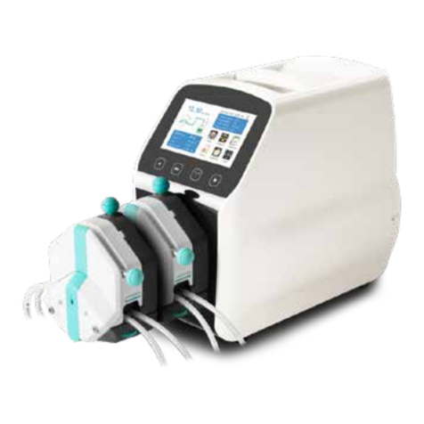
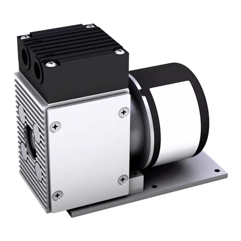
Flow Controller Systems FCS KA6/12 User manual

FCS KA6/12
Basic Peristaltic Pump
Operation Manual
!"#$%&'()*+)%,-./%0'*1.%2$$/%3456'1%7+..)/%7,%"8#"9%%%%%%%%%%%%
"!#:#;<:88#"%=%>'(1*6?@A(:'(B6.1%%%%%%%%%%%
!"#$%#&'(#"")(*+*'),*-%#,

KA6/12
2
Note:
Ø Please read the manual carefully before operating the product.
Warning:
Ø Tubing may have crack due to wear. It results in the overflow of fluid from tubing. In that time human body and instruments may be
harmed. Users must check frequently and change tubing in time.
Ø Connect the power cord to the wall socket directly, and avoid using the extended electric wire.
Ø If the power cord or plug had wear and other damage, please disconnect the plug. (Hold the plug instead of the wire)
Ø If following situations happened, please turn off the power supply and disconnect the plug. (Hold the plug instead of the wire)
1. Fluid splash on the pump.
2. You think the pump need to maintain or repair.
Ø The user’s power socket must have ground wire, and have reliable grounding.
Note: The foot pedal switch and other external control plugs must be connected or disconnected in the power-off status to prevent the external
control interface from being burned

KA6/12
3
Catalogue
1. Product Instruction ................................................................................................................................................................................ - 4 -
2. Product Appearance .............................................................................................................................................................................. - 4 -
3. Product Keypad Instruction .................................................................................................................................................................. - 4 -
4. External Control Interface Instruction .................................................................................................................................................. - 5 -
5. Technical Specifications ....................................................................................................................................................................... - 7 -
6. Main Functions and Features ................................................................................................................................................................ - 8 -
7. Dimension Drawing .............................................................................................................................................................................. - 8 -
8. Maintenance ........................................................................................................................................................................................ - 10 -
9. Warranty and After Sales Service ....................................................................................................................................................... - 11 -

KA6/12
- 4 -
1. Product Instruction
M6 series pump speed range is 0.1-600 rpm, flow rate range is 0.211~12000 ml/min.
Adjust speed manually or automatically through external control interface. Power-down memory function, when re-power on, the pump will
work with previous status. Timing test function, timing range: 0.5~999s, it is convenient for calibration and test. It can support 7 different
external control modes, make more convenient.
2. Product Appearance
A- Drive
B- Pump head
C- External control interface
D- Power socket
E- Internal fuse
F- Power switch
3. Product Keypad Instruction
l Start /stop button
Control the pump start and stop, press this button once the pump work status change once. When the pump runs, the start/stop indicator light
is on. When the pump stops, the start/stop indicator light is off.
l Direction button
Control the pump working direction, press the button once, the drive work status change once. When the pump runs left, the left indicator
light is on. When the pump runs right, the right indicator light is on.
l Digital knob
(1) Turn it left or right is to adjust the motor speed when displays the speed.
(2) Press down the knob then release in stop status, enter RS485 address setting interface, then a number occur and flashes, now turn the
knob to change address, press the knob again to confirm and escape from this setting.

KA6/12
- 5 -
(3) In internal control mode, keep pressing this knob, the pump runs with full speed, LED display “FULL”. Release the knob, it displays
the pump return to normal speed.
l External control button
The external control mode button is enabled only when the pump stops working. It used for changing between different external control
modes that is 7 different modes in total.
In internal control mode, the external control mode indicators all light off.
(1) Only external control start/stop mode: the external control start/stop indicator light on, external control direction and speed indicators
light off.
(2) Only external control direction mode: the external control direction indicator light on, external control start/stop and speed indicators
light off.
(3) Only external control speed mode: the external control speed indicator light on, external control start/stop and direction indicators
light off.
(4) External control start/stop and direction mode: the external control start/stop and direction indicator light on, external control speed
indicator light off.
(5) External control start/stop and speed mode: the external control start/stop and speed indicator light on, external control direction
indicator light off.
(6) External control direction and speed mode: the external control direction and speed indicator light on, external control start/stop
indicator light off.
(7) External control start/stop, direction and speed mode: the external control start/stop, direction and speed indicators all light on.
Note: When external control indicator light on, the relative internal control buttons cannot be used.
l Timing test button
Timing test button only work when the pump is in internal control mode and when the pump stops running. Keep press Timing test button
more than 3 seconds then enter the setting timing interface, turn the digital knob left or right to adjust the timing, press the Timing test button
again, back to the working interface. In stop status, press the Timing test button, the pump will run with current speed and the set test time,
when the set test time is run out of, it will stop automatically. This function usually used for calibration or flow rate test. (If press the star/stop
button during the test, the pump will stop running. Press the Timing test button again, the pump will re-clock.)
4. External Control Interface Instruction
The 15-pin connector on the back of pump control the pump through external signals, when leaving the factory, the company will have a
standard external control line, the wiring definition as below:
1
9
2
10
3
11
12
5
13
6
14
7
15
8
4
0-5V
WK-SPEED-
ActiveWK-RUN/STOP
ActiveWK-DIRECT
485B-
WK-RUN/STOP
485A+
WK-DIRECT
232-T
GND/232-GND
232-R
Active-GND
0-10V
4-20mA

KA6/12
- 6 -
(1) Pin 1, 0-5V: Connecting positive pole for the signal that controlling the motor speed, 0-5V connecting wiring port.
(2) Pin 2, WK-RUN/STOP: External control start/stop input port (Passive signal: Motor running in normal closed status, motor stop
running in normal open status.)
(3) Pin 3, WK-DIRECT: External control motor running direction signal input port. (Passive signal: Motor running in right in normal
closed status, motor running in left in normal open status. )
(4) Pin 9, WK-SPEED-: Connecting signal negative pole that controlling motor speed.
(5) Pin 10, 0-10V: Connecting signal positive pole that controlling motor speed, 0-10V connecting wiring port.
(6) Pin 11, 4-20mA: Connecting signal positive pole that controlling motor speed, 4-10mA connecting wiring port.
(7) Pin 15, GND: Ground wire.
Note:
1) External control start/stop, direction signal all are passive signal.
2) The external control plugs must be connected or disconnected in the power-off status to prevent the external control interface from
being burned.
DB15 external control port regular wire sequence as below:
RS232 Communication Pin Definition
1) Pin 6, 232-T: The host computer sends data port, connect to DB-9 connector Pin 3.
2) Pin 7, 232-R: The host computer receive data port, connect to DB-9 connector Pin 2.
3) Pin 15. GND: Ground wire, connect to DB-9 connector Pin 5.
RS485 Communication Pin Definition
1) Pin 4, 485-B-: 485 communication signal port, connect with 485 converter B-.
2) Pin 5, 485-A+: 485 communication signal port, connect with 485 converter A+.
模拟信号0-5V
模拟信号负极
DB15外控接口
1脚
2脚
3脚
15脚
9脚
GND
WK-RUN/STOP
WK-DIRECT
10脚
11脚
模拟信号0-10V
模拟信号4-20mA
Pin 1
Pin 2
Pin 3
Pin 9
Pin 10
Pin 11
Pin 15
External Control Interface for DB15
Analog Signal 0-5V
WK-RUN/STOP
WK-DIRECT
The Negative Pole of
Analog Signal
Analog Signal 0-10V
Analog Signal 4-20mA
GND

KA6/12
- 7 -
Isolated External Control Pin Definition
1) Pin 12 Active WK-RUN/STOP: Isolated external control start/stop signal input port (Active signal: 5-24V).
2) Pin 13, Active WK-DIRECT: Isolated external control direction signal input port (Active signal: 5-24V).
3) Pin 14, Active-GND: Isolated external control signal input ground wire.
Isolated External Control Wiring Diagram
l M6 series pump drive could be equipped with foot pedal and dispenser, if you need, please contact us.
5. Technical Specifications
Flow rate
accuracy
<±0.5%
Display
3 digital LED
Control
Mechanical keypad
External control
Switch signal
Speed range
0.1-600rpm
Speed control
Digital knob
Speed
resolution
0.1rpm (0-100rpm)
1rpm (100-600rpm)
External speed
control signal
0-5V,
0-10V, 4-20mA
(optional)
Timing test
range
0.5-999s
Power supply
AC 220V±10%
50Hz/60Hz(standard)
AC 110V±10%
50Hz/60Hz(optional)
Temperature
0-40℃
Communication
RS232 N232 protocol
RS485Modbus
protocol
IP rate
IP31
Relative
humidity
<80%
Power
consumption
M6-3L
<80W
M6-6L
<180W
M6-12L
<300W
Flow rate
range
M6-3L
0.211-3600ml/min
M6-6L
0.3-6000ml/min
M6-12L
0.00069-12L/min
DB15外控接口
12脚
13脚
14脚
有源信号
5-24 V
External Control Interface for DB15
Pin 12
Pin 13
Pin 14
Positive signal
5-24V

KA6/12
- 8 -
6. Main Functions and Features
Ø Digital knob control speed manually or automatically through external control interface.
Ø Timing test function, it is convenient to test the flow rate within specified time.
Ø Full speed button with filling and emptying functions.
Ø RS232 communication interface with Shenchen-N232 communication protocol.
Ø RS485 communication interface with standard MODBUS communication protocol.
Ø High torque, heavy flow, large suction and lift.
Ø The driving circuit has excellent performance, good heat dissipation condition, low noise, smooth operation and power-down
memory function.
Ø Excellent cost performance.
7. Dimension Drawing
(Unit: mm)
7.1 Single Pump Head
YZ35 Pump Head
DZ25-3L Pump Head

KA6/12
- 9 -
DZ25-6L Pump Head
EasyPump Pump Head
7.2 Product Dimension
M6-3L + EasyPump

KA6/12
- 10 -
M6-3L + DZ25-3L
M6-6L + DZ25-6L
M6-12L + YZ35
8. Maintenance
Ø When the pump does not work, please loose the cartridges of pressing the tubing for avoiding changing the shape of tubing because of
longtime extrusion.
Ø The surface of drive and pump head do not resist strong corrosive liquids, please pay attention to this when use the pump.
Ø Keep the pump rollers clean and dry. If the rollers is not clean, it will increase the tubing wearing, shorten the tubing life and make the
rollers damage very soon.
Ø If there is liquid drop on the rollers, clean it as soon as possible. Longtime moisture can lead the rollers damage.

KA6/12
- 11 -
9. Warranty and After Sales Service
We support 3 years warranty for the pumps, subject to the exceptions below. Our company shall not be liable for any loss, damage, or
expense directly or indirectly related to or arising out of the use of its products. This warranty does not obligate our company to bear any
costs of removal, installation, transportation, or other charges which may arise in connection with a warranty claim.
If the pump fails during the warranty period, after confirmation by our technical department, we will provide spare parts free of charge.
Customers will need to bear the shipping cost.
Exceptions:
Ø The warranty shall not apply to repairs or service necessitated by normal wear and tear or for lack of reasonable and proper maintenance.
Ø All tubing and pumping accessories as consumable items are excluded.
Ø Electrical surge as a cause of failure is excluded.
Ø Chemical attack is excluded
Ø Improper operation or man-made damage as a cause of failure is excluded.
Flow Controller Systems
2950 Buskirk Ave Suite 300 Walnut Creek CA 94597
Tel: 925 -516-4459
Website: flowcontrollersystems.com
Email: justin@fcs-us.net
Table of contents
Other Flow Controller Systems Water Pump manuals
Flow Controller Systems
Flow Controller Systems FCS KA1 User manual
Flow Controller Systems
Flow Controller Systems FCS KA SS User manual
Flow Controller Systems
Flow Controller Systems FCS KA User manual

Flow Controller Systems
Flow Controller Systems FCS KA-DISP User manual
Flow Controller Systems
Flow Controller Systems FCS KA6 User manual