Flow Controller Systems FCS KA User manual

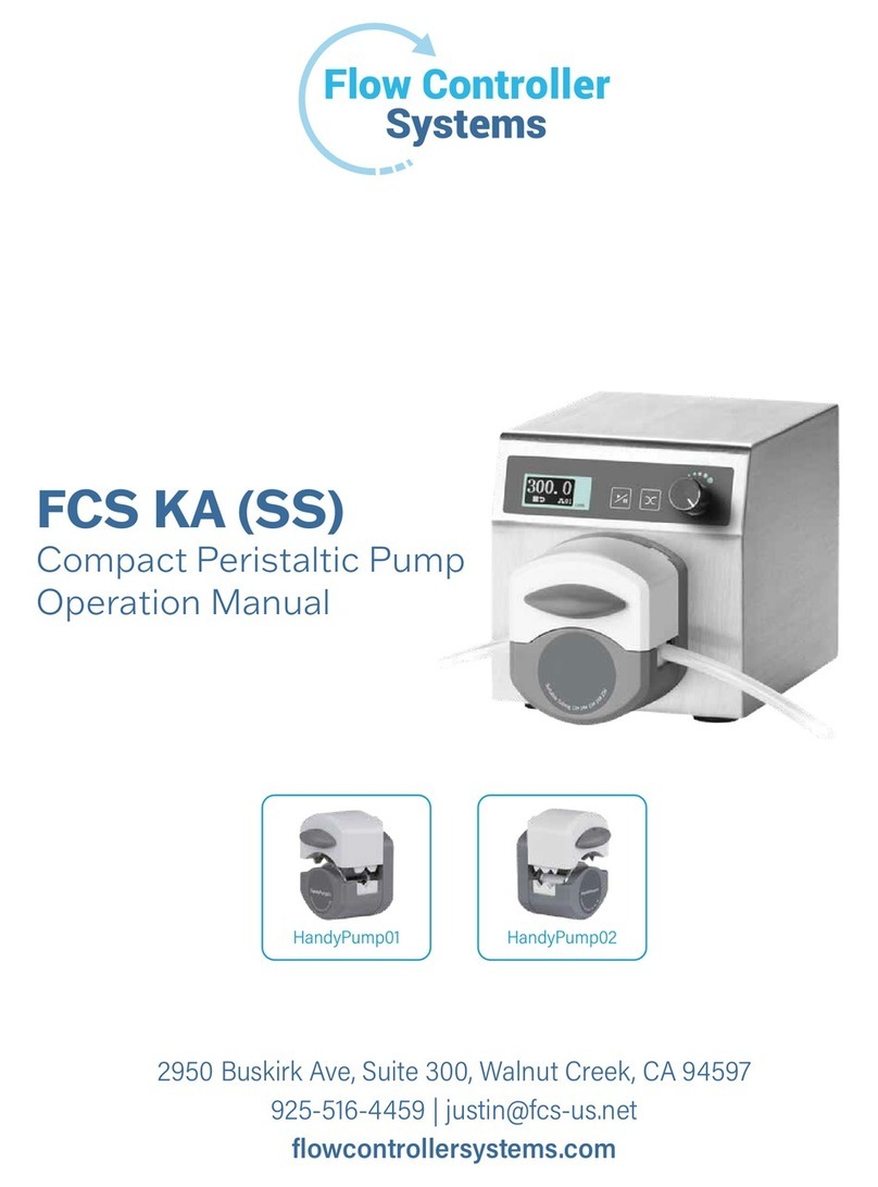
FCS KA (SS)
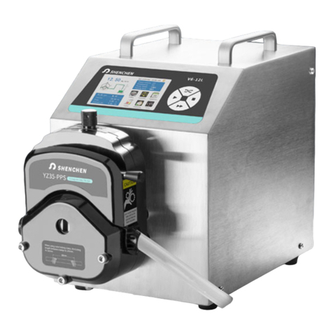
Compact Peristaltic Pump
Operation Manual

Note:
Please read the manual carefully before operating the product.
Warning:
Connect the power cord to the wall socket directly, and avoid using a power
extension cord.
If the power cord or plug has wear or other damage, please disconnect the plug.
(Hold the plug instead of the wire.)
If following situations happen, please turn off the power supply and disconnect
the plug. (Hold the plug instead of the wire.)
1. Fluid splash on the pump.
2. You think the pump needs to be maintained or repaired.
The user's power socket must have a ground wire with a reliable grounding.
Note: The foot pedal switch and other external control plugs must be connected and
disconnected in the power-off status to prevent the external control interface from
being burned.

Catalogue
1. Product Introduction ........................................................................................... - 1 -
2. Product Appearance ............................................................................................ - 1 -
3. Operation Panel .................................................................................................. - 2 -
4. External Control Instruction ............................................................................... - 3 -
5. Communication Function Instruction ................................................................. - 7 -
6. Technical Specification ....................................................................................... - 8 -
7. Main Function and Feature ................................................................................. - 9 -
8. Dimension Drawing ............................................................................................ - 9 -
9. Maintenance ..................................................................................................... - 10 -
10. Warranty & After-Sales Service ...................................................................... - 12 -

FCS KA (SS)
-1 -
1. Product Introduction
FCS KA (SS), with low noise and stable operation, is driven by an integrated stepper
motor with a compact structure. The product adopts OLED blue screen display and
has an external control interface, which can realize remote control. It can communicate
with a computer through standard Modbus communication protocol (RTU mode).
2. Product Appearance
A
B
C
DF
E
G
H
A—— Operation panel
B—— Drive
C—— Pump head
D—— Fan interface
E—— Power supply switch
F—— USB interface
G——External control interface
H——Power supply socket

-2 -
3. Operation Panel
Direction Digital Knob
EXT
Start/stop
Ext. control
100.0
V 01
转速
通信地址
模拟调速
运行状态
5V 01
Speed
Analog speed
control
Operation
status
Communication
address
Start/Stop Button
Pumps start/stop can be controlled by this button. Press this button once, the pump
working status change once. When the drive runs, the screen displays ‘▶’, when the
pump stops, the screen displays ‘■ ’.
Direction
This button is used to change the motor running direction. Press this button once and
the running direction of pump changes once.
External control button
This button is used to change the method of analog speed control. Press this button
once and that will cycle the display: Empty→5V→10V→mA→Empty. Respectively
corresponding to: Turning off analog speed regulation→0-5V→0-10V voltage analog
speed regulation →4-20mA analog speed regulation →Turning off analog speed
regulation.
Note: If you keep pressing this button and turn on the power supply of this device at
FCS KA (SS)

-3 -
the same time, it will initialize the device and all the parameters will be lost.
Digital Knob
The digital knob used to increase or decrease the motor speed.
(1) In the running state, the digital knob is used to adjust the speed. Turn
clockwise to increase the speed, turn counterclockwise to decrease the speed. If
you keep pressing the digital knob, the motor will run at the highest speed (full
speed), and release it to return to normal speed.
(2) In the stop state, press the digital knob, the lower right corner of the OLED
flashes and the value is RS485 communication address (1~32). At this time, you
can rotate the digital knob to change the value. After setting, press the digital
knob to save the data and the screen no longer flashes.
4. External Control Instruction
FCS KA (SS) series has a 15-pin interface for the external control interface, as the
below figure shows. That includes the function of external control start/stop, direction,
analog speed regulation, communication, and status output.
1
15
5
610
11
1
5
6
10
11
15
Pin 1, port of external control start/stop
Pin2, port of external control direction
Pin3, external control level mode switching
Pin4, RS485B-
FCS KA (SS)

-4 -
Pin5, RS485A+
Pin6, analog speed regulation 0-5V signal terminal
Pin7, analog speed regulation 0-10V signal terminal
Pin8, analog speed regulation 4-20mA signal terminal
Pin9, analog speed regulation common terminal AGND
Pin10, active external control isolated signal common terminal, factory defaults
passive external control signal, and this pin is empty
Pin11, status output negative terminal (POWER_GND)
Pin12, status output terminal (OUT_RUN)
Pin13, status output active terminal (POWER_VDD)
Pin14, internal isolated 5V output active terminal
Pin15, internal isolated 5V output negative terminal
(1) Passive external control start/stop, direction
Pulse mode:
Pin1 to Pin14, short circuit break (pulse mode) is start, short circuit break again is stop.
Pin2 to Pin14, short circuit break (pulse mode) is direction.
Level mode:
Pin3 is external control level mode switching. Short circuited Pin3 and Pin14 to switch
to external control level mode.
Pin1 to Pin14, short circuit is start, breaking them is stop.
Pin2 to Pin14, short circuited, motor is counterclockwise, breaking them, motor is
clockwise.
Note: External start/stop and direction is defaulted to passive signal when leaving
factory. This interface could be connected with a foot pedal equipped by our company.
(2) Active external control start/stop, direction
Pulse mode:
Pin10 connects with negative pole of active external control signal.
Pin1 connects positive pole of active external control signal, short circuit and then
disconnect, the motor will start. Do it again, the motor will stop.
FCS KA (SS)

-5 -
Pin2 connects positive pole of active external control signal, short circuit and then
disconnect, the motor will change direction. Do it again, the motor will change
direction again.
Level mode:
Pin10 connects with negative pole of active external control signal.
Pin3 is the pin of external control level mode switching. Short circuited Pin3 and
positive pole of active external control signal switches to external control level mode.
Short circuited Pin1 and positive pole of active external control signal is start, breaking
them is stop.
Short circuited Pin2 and positive pole of active external control signal, the motor is
counterclockwise, break them, the motor is clockwise.
Note: The active external control isolated signal is 5V, 12V, 24V (Universal)
(3) Analog speed regulation
0-5V voltage signal speed regulation
Choose the analog speed regulation signal of the pump to 0-5V voltage signal by
external control button. The analog signal is displayed “5V” in the screen.
Voltage 0-5V speed regulation, Pin6 connects to the positive pole of voltage analog 0-
5V signal. Pin9 to the connects negative pole. Change the voltage value of the analog
signal and the speed changes linearly. 0V corresponds to speed 0rpm, 5V corresponds
to maximum speed.
0-10V voltage signal speed regulation
Choose the analog speed regulation signal of the pump to 0-10V voltage signal by
external control button. The analog signal is displayed “10V” in the screen.
Voltage 0-10V speed regulation, Pin7 connects to the positive pole of voltage analog
0-10V signal. Pin9 connects to the negative pole. Change the voltage value of the
analog signal and the speed changes linearly. 0V corresponds to speed 0rpm, 10V
corresponds to maximum speed.
External control button for current signal speed regulation
Choose the analog speed regulation signal of the pump to current signal and the analog
FCS KA (SS)

-6 -
signal is displayed “mA” in the screen.
Current 4-20mA speed regulation, Pin8 connects to the positive pole of current analog
4-20mA signal. Pin9 connects to the negative pole. Change the current value of the
analog signal and the speed changes linearly. 4mA corresponds to speed 0rpm, 20mA
corresponds to maximum speed.
Note: DO NOT connect the 0-5V/0-10V signal with 4-20mA input terminal. Wrong
connections may cause damage to the device. The external control plugs must be
connected and disconnected in the power-off status to prevent the external control
interface from being burned.
(4) Output signal
1) Connect Power-VDD with the positive pole of external connection power supply
5 V.
2) Connect Power-GND with the negative pole of external connection power
supply 5V.
3) Start motor, relay pull-in; Motor stops, relay breaks.
FCS KA (SS)

-7 -
5. Communication Function Instruction
The pump supports standard modbus protocol (RTUmode), communication modes are
RS485 and USB. It can control the pump start/stop, direction and motor speed, and
can read the current running status.
USB communication mode: A USB cable is needed (one side is USB-A and the other
side is USB-B). Connect the pump with a computer through the USB interface.
Type-A connects computer USB interface
Type-B connects KA (SS) USB
interface
Type Type-A Type-B
Plug(male)
USB2.0
4 3 2 1
Type-A
1 2
4 3
Type-B
Connect with
computer Connect with external control USB interface
RS485 communication: Connect A+ (pin5) from external control interface (as shown
in Picture) to T/R+ of RS485 module; and connect B- (pin4) to T/R- of RS485 module.
Users can control the pump working according with the communication protocol.
FCS KA (SS)

-8 -
RS485 conversion
module
6. Technical Specification
Flow rate 0.0033~365.69
mL/min Power supply AC100V~240V(50HZ/60HZ)
Speed range 0.1~300rpm External control
Start/stop: Switch signal
Speed control: 0-5 V, 0 -10V, 4-
20mA for option
Speed
resolution 0.1rpm Communication RS485
Control
Digital knob/
pure imported
keypad
Temperature 0-40℃
Motor 57 closed -loop
stepper motor
Relative
humidity <80%
Display OLED Output interface Output motor working status
Power
consumption ≤75W IP rate IP31
FCS KA (SS)

-9 -
7. Main Function and Feature
Suitable Pump Head: FCS KA (SS) easy load pump head.
Digital knob control speed, control speed manually or by external control
interface automatically.
Multiple pumps can be controlled by one controller at the same time, RS485
address cannot be repetitive.
The circuit has excellent performance, good heat dissipation conditions, low
working noise, stable operation, and has power-off memory function.
RS485 standard Modbus protocol, that is more convenient to connect with PLC.
304 stainless steel shell, anti-corrosion, no rust, conforms to GMP requirements.
OLED displays motor speed and working status.
8. Dimension Drawing
Unit: (mm)
FCS KA (SS)

-10
9. Maintenance
9.1 Check the running status of the machine before starting it, ensure that the power
supply of the device is reliably grounded. Normal operation can be put into use. The
external wiring of the equipment must be operated in the power-off state to prevent
burning the equipment.
9.2 Check to see if the tubing is damaged or the equipment is leaking and ensure that
the liquid in the tubing is discharged to the container or discharge pipe. Wipe any
leaked liquid around the pump quickly and correct any possible faults promptly. Keep
the rollers of the pump head clean and dry, otherwise it can hasten tubing wear (it can
also damage the tubing causing solid substances in the liquid), reduce the useful life
of tubing, and lead to quicker damage and wear to the rollers. If the pump head gets
water on it accidently, use a soft, absorbent cloth to wipe it dry to prevent damage to
the pump head. If liquid splashes on the pump, please turn off the power supply and
unplug the power wiring. Check to see if there is liquid in the inner part of the
equipment, if so please contact the manufacturer.
9.3 The factors affecting the flow are as follows:
1) The inner diameter and wall thickness of tubing may have some deviations due
to its tolerance and different bathes.
2) Different liquid properties
3) It will decrease flow rate when input port and output port change incrementally
or there are suction and lift.
4) The speed of DC/AC motor will change according to load, temperature and
humidity.
This may influence product flow accuracy, please leave a margin when choose tubing.
9.4 This product has no waterproof measures. Please take protective measures when
using in a wet environment. When the product will not be in use for a long time, please
clean it and keep it in a dry and ventilated environment.
9.5 Pump head is not resistant to organic solvent (Except for special indication) and
strong corrosive liquids, please be attentive when using either near it.
FCS KA (SS)

-11
9.6 The data used for testing in this manual is all short duration and may change for
longer duration use.
9.7 The current will raise over the rated running current when DC/AC motor starts or
blocks, it may be about 3-5 times the rated operating current.
9.8 This product does not have special certification such as medical certification.
When it needs to be used in special fields such as medical and military, please self-
certify. Load changes will also cause changes in operating current. Therefore, please
conduct margin design for power supply power.
9.9 The company shall not bear the direct and indirect losses caused by the malfunction
or improper operation of this product.
FCS KA (SS)

-12
10. Warranty & After-Sales Service
We support 3 years warranty for the pumps, subject to the exceptions below. Our
company shall not be liable for any loss, damage, or expense directly or indirectly
related to or arising out of the use of its products. This warranty does not obligate
our company to bear any costs of removal, installation, transportation, or other
charges which may arise in connection with a warranty claim.
If the pump fails during the warranty period, after confirmation by our technical
department, we will provide spare parts free of charge. Customers will need to bear
the shipping cost.
Exceptions:
The warranty shall not apply to repairs or service necessitated by normal wear
and tear or for lack of reasonable and proper maintenance.
All tubing and pumping accessories as consumable items are excluded.
Electrical surge as a cause of failure is excluded.
Chemical attack is excluded.
Improper operation or man-made damage as a cause of failure is excluded
FCS KA (SS)
Flow Controller Systems
2950 Buskirk Ave Suite 300 Walnut Creek CA 94597
Tel: 925-516-4459
Website: flowcontrollersystems.com
Email: justin@fcs-us.net
This manual suits for next models
1
Table of contents
Other Flow Controller Systems Water Pump manuals
Flow Controller Systems
Flow Controller Systems FCS KA-DISP User manual
Flow Controller Systems
Flow Controller Systems FCS KA SS User manual
Flow Controller Systems
Flow Controller Systems FCS KA6 User manual
Flow Controller Systems
Flow Controller Systems FCS KA1 User manual
Flow Controller Systems
Flow Controller Systems FCS KA6/12 User manual
