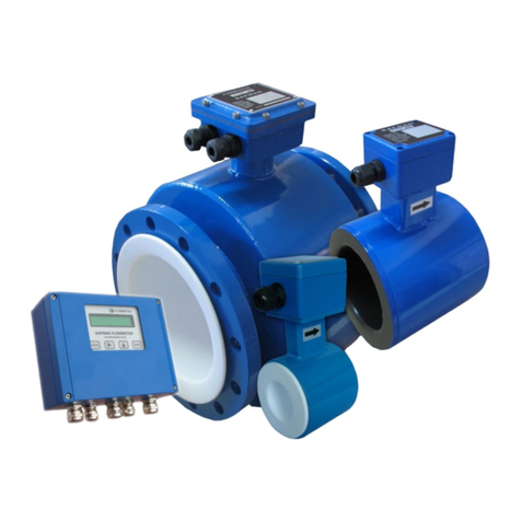
FLOW metrix SAFMAG BETA METER User manual

Safmag House P.O.Box 17143 Int Tel.: +27(0)312060630
498 Sydney Road Congella SA Tel.: 086 110 6028
Durban Reg. No. CK 1986/011597/23 www.flowmetrix.co.za
USER’S GUIDE
Installation & Operation
Instructions
ΒETA METER
ELECTROMAGNETIC FLOWMETER
16

Safmag House P.O.Box 17143 Int Tel.: +27(0)312060630
498 Sydney Road Congella SA Tel.: 086 110 6028
Durban Reg. No. CK 1986/011597/23 www.flowmetrix.co.za
INDEX
Page :
Introduction 1
Installation guides 2
Meter Body 3
Flow Rate Guide 4
Safmag Magprobe (Insertion Mag) 5
Wiring Diagram 6
Empty Pipe Detection Link 6
General 7
Output Functions 7
Keypad System 9
Menu System / setup 9
Main Menu 10
Batching Function 11
Flow Data Menu 12
Setup Data Menu 14
Cal Mode 16
Modbus RTU 17
Error Messages/ Troubleshooting 19
Features & Specifications 20
Testing of Flowtube 21
Warranty 23

1 Instruction Manual
Introduction
The Safmag β-meter provides cost effective measurement of flowrate in
applications where mechanical flowmeters are traditionally utilized. The design
concept has focused on simplicity, whilst retaining all benefits associated with the
use of an electromagnetic flowmeter.
The β-meter comprises a flowtube sensor and a display unit which is mounted
remote from the sensor. The display unit utilises a high speed 16 bit
microprocessor with 32 Kbyte flash memory. The flow total and flow rate are
displayed on a LCD display.
Theory of Operation
The operation of an electromagnetic flowmeter is explained by reference to Faraday’s law of
electromagnetic induction. This law states that the voltage induced across an electrical
conductor, as it moves at right angles through an electromagnetic field, is directly proportional
to the velocity of that conductor through the field. Mathematically this statement is
represented as shown below:
E = constant x B L V
Where: E = the induced voltage
B = the electromagnetic field strength
L = the length of the conductor in the field
V = the velocity of the conductor (average velocity of the medium)
The volumetric flow of a conducting liquid or slurry is derived as follows:
Let L = D (the diameter of the meter)
Then E = constant x B D V
Volumetric flow Q = V A (where A is the Cross-sectional area of the pipe)
Combining the above equations it is seen that if field strength is held constant then
E = K.Q (where K is a constant), thus the induced voltage is directly proportional
to the volumetric flowrate.

2 Instruction Manual
Installation guides
Remote Electronics
The remote electronics display may be mounted up to 100 metres from the meter body using
SAFMAG cable. It should be mounted on the wall or a pipe stand. The display housings have
dedicated points for mounting. DO NOT drill into the enclosure, this will void IP rating and
warranty. Avoid direct sunlight on the LCD display as this can make it difficult to read and
cause fading over time. If mounted in an area where there is exposure to direct sunlight it is
advisable to mount the display facing south and provide shade. Avoid mounting the display in
any area where there is a possibility of flooding.
Avoid mounting near VSD (variable speed drives) and motors.
The β-meter r is not rated for use in hazardous areas.
Flowtube (Fullbore sensor)
While installing the meter it is recommended to follow the arrow marking [] on the flowmeter
tube, which indicates the direction of flow. If the meter is installed in the opposite direction to
that indicated by the arrow, the meter will read zero or reverse flow under all flow conditions.
This situation can be remedied by reversing the wires marked COIL on the electronic board.
The flowtube may be installed in horizontal or vertical pipelines. If installed horizontally, the
measuring electrodes should be in the horizontal plane avoiding the possibility of bubbles in
line. The flowtube should be full of liquid at all times. Install the flowtube with at least 3 pipe
diameters of straight pipe upstream, and 2 pipe diameters downstream. Ensure that the
gaskets do not protrude into the pipe. This could affect accuracy of the flowmeter. Flowtubes
installed in non-conductive pipework (e.g. PVC HDPE) or lined pipework should have earthing
rings installed and electrically bonded to the flowtube ground. Bonding the flowtube to earth
spike will improve lightning protection.
OPEN CHANNEL INSTALLATION
3 x D min
2 x D min

3 Instruction Manual
Meter Body
The flowmeter should be lifted by a rope sling being passed around the outside of the meter or,
in the case of the large meters the lifting lugs should be used. Never pass a cable or beam
through the flowtube for lifting purposes, as this will damage the flowtube liner and render the
meter unusable. Do not support the meter by its case.
Check for alignment and spacing of pipe work, as the meter should not be used to pull pipe
work into alignment. Table overleaf gives face to face and overall dimensions for the various
sizes and types of meter.
Place flange gaskets on the flange faces of the meter and position the meter between the
flange faces of the piping. Gaskets should be cut 3 mm larger than the inside diameter of the
pipe.
Insert bolts through the flanges and run washers and nuts onto the bolts. Check the piping for
alignment and the gaskets for concentricity. Tighten the nuts evenly – do not over tighten as
this may damage the liner. Bolt torque should be limited to that which will produce a positive
seal.
Application Guidelines
1. The velocity at maximum flow should be greater than 1 m/s. (select the meter size
accordingly)
2. The minimum flow velocity the flowmeter will measure is 0,1m/s.
3. The maximum velocity the flowmeter will measure is 10 m/s
4. The conductivity of the liquid should be greater than 20μs/cm.

4 Instruction Manual
FLOW RATE GUIDE
PIPE
SIZE
PIPE
SIZE FLOWRATE @ 1m/s (3ft/s ) FLOWRATE @ 10m/s (30ft/s)
(mm) (INCH) (l/s) m3/hr ft3/s gal(US)/s (l/s) m3/hr ft3/s gal(US)/s
10 0.4 0.08 0.28 0.003 0.02 0.78 2.82 0.03 0.21
15 0.6 0.18 0.64 0.006 0.05 1.76 6.36 0.06 0.46
25 1 0.5 1.8 0.02 0.13 5 18 0.18 1.32
40 1.6 1.25 4.5 0.04 0.33 12.5 45 0.44 3.30
50 2 2 7.2 0.07 0.53 20 72 0.71 5.28
65 2.6 3.3 11.9 0.12 0.87 33 118.8 1.17 8.72
80 3.2 5 18.0 0.18 1.32 50 180 1.77 13.2
100 4 8 28.8 0.28 2.11 80 288 2.83 21.1
125 5 12 43.2 0.42 3.17 120 432 4.24 31.7
150 6 18 64.8 0.64 4.75 180 648 6.36 47.5
200 8 31 111.6 1.09 8.19 310 1116 10.95 81.9
250 10 49 176.4 1.73 12.9 490 1764 17.30 129.4
300 12 70 252.0 2.47 18.5 700 2520 24.72 184.9
350 14 96 345.6 3.39 25.4 960 3456 33.90 253.5
400 16 125 450.0 4.41 33.0 1250 4500 44.14 330.1
450 18 159 572.4 5.62 42.0 1590 5724 56.15 419.9
500 20 196 705.6 6.92 51.8 1960 7056 69.22 517.6
600 24 283 1018.8 9.99 74.7 2830 10188 99.94 747.4
700 28 385 1386.0 13.60 101.7 3850 13860 135.96 1016.8
750 30 442 1591.2 15.61 116.7 4420 15912 156.09 1167.3
800 32 500 1800.0 17.66 132.1 5000 18000 176.57 1320.5

5 Instruction Manual
Safmag Magprobe (Insertion mag)
Flow rate = ( 0 – 6 m/s ) / ( 0 – 18 ft/s )
The insertion probe must only be installed with the flow in the direction of the
arrow marking.
The alignment of the probe is important for accurate flow measurement, and care
should be taken to ensure that the point indicator on the terminal box mounting
plate points along the axis of the pipe. We recommend that the measuring section
of the probe is positioned at the centre of the pipe. As the probe has a 65mm
measuring window, this insertion depth is not critical but the following procedure
should be followed.
Installation
1. Measure the pipe Circumference and calculate the Outer Diameter. OD = C/π.
2. Measure the distance from the top of the securing nut to the pipe wall. (X)
3. Calculate the insertion depth from the probe tip A = X + (OD / 2) + 50mm.
4. Mark probe at “A” distance from the probe tip.
5. Care must be taken when installing under pressure. Make use of the threaded
bar and pull pate to safely pull the probe into place.
6. With the O-ring seal and securing nut in place insert the probe to the mark and
tighten the 4 allen screws to loosely clamp the probe.
7. Align the probe with arrow forward, check insertion depth and tighten securing
nut and probe clamp with four allen screws.
X
A
t
OD / 2
50mm
ID

6 Instruction Manual
EPD LINK
WHITE
BLACK
BLACK
WHITE
YELLOW
ORANGE
Over All Screen
WHITE
ORANGE
WHITE
YELLOW
Empty Pipe
D
etection Link (EPD)
The β – meter incorporates an
EPD circuit. The EPD is activated
with the EPD link inserted, and de-
activated with the link removed.
For successful EPD it is
recommended that the length of
interconnecting cable is limited to
15 metres
SCREEN
SCREEN
SCREEN
SCREEN
Wiring Diagram
COIL (B)
COIL (W)
24 Vdc
PLS3 +
PLS3 -
PLS2 +
PLS2 -
PLS1 +
PLS1 -
SCREEN
E (Earth)
N (
-
)
L (+)
COIL
COIL
E1
SCRN
EARTH
SCRN
E2
REMOTE DISPLAY
FLOWTUBE
GND
B
A
E2 (Y)
SCRN2
GND (O/B)
GND (O/B)
SCRN1
E1 (W)
SOCKET
PLUG (PULL TO
REMOVE)
PLUG (PULL TO
REMOVE)
Remote Display
Flowtube
4-20mA -
4-20mA+

7 Instruction Manual
General
The β-meter display/signal converter allows a fast response time for the sensors ≤150NB.
This is achieved by automatically selecting higher coil frequencies permitting faster update
times for flow calculations.
These features allow batching of small volumes and ensure an acceptable accuracy.
Size 50Hz Power Supply 60Hz Power Supply
Coil Frequency Update Time Coil Frequency Update Time
10-25mm 12.5Hz 80ms 15.0Hz 66.66ms
26-150mm 6.25Hz 160ms 7.5Hz 133.33ms
151-800mm /
Insertion Mag
3.125Hz 320ms 3.75Hz 266.66ms
Output Functions
4-20mA
The 4 – 20mA output signal is proportional to the flow rate. 4mA = 0 flow rate. The full-scale
value (i.e. 20mA) is the flow rate figure programmed into menu item M1_2.
OUTPUT
BETA TERMINALS
EXT. CIRCUIT
SIGNAL
Flow rate
Current Loop
(Active)
Open Collector Transistor
The open collector transistor outputs OCT1, OCT2, and OCT3 are individually programmable
for any of the following functions.
Forward flow totaliser pulse output, Batch control function, No coil current alarm, Empty pipe
alarm, Pulse output alarm (i.e. frequency > 1250Hz), Reverse flow alarm, Low flow rate alarm,
High flow rate alarm.
The output signal can be wired as:
Open collector output between the PULS+ and PULS- terminal when the switch is OFF.
24V binary signal available between the PULS+ and PULS- terminal when the switch is ON
Pulse Output
Menu option M2_7 volume/pulse is used to determine the pulse frequency
The pulse width is determined by the M2_8 puls-width programmed unless –
1. pulse frequency exceeds the coil frequency or
2. frequency cannot accommodate the programmed pulse width
then output will change to pulses with equal mark space ratio.
It is important to remember that the flow sensor size determines the coil’s frequency.
+
-
4-20mA-
4-20mA+ +
mA
-
RLOAD < 600Ω
mA
%
0
20
100
4

8 Instruction Manual
OCT 1/2/3
OUTPUT
BETA TERMINALS
EXT. CIRCUIT
SIGNAL
External supply and
pull up resistor
External supply and
relay/counter
Internal supply and
relay/counter
Internal supply and
external pull up
resistor
Relay/
Mechanical
Totaliser
Etc.
PLC GND
PLC IN
470Ω MIN
0.05A MAX
24V
MAX
PULSE – ISO GND
0.8V
24V
PULSE – ISO GND
0.8V
24V
PULSE – ISO GND
0.8V
24V
PULSE – ISO GND
0.8V
24V
GND
0.05A MAX
24V MAX
0.05A MAX
PLC GND
PLC IN 470Ω MIN
0.05A MAX
PLS
-
PLS 1/2/3
Relay
PLS -
PLS 1/2/3
PLS
-
PLS 1/2/3
PLS
-
PLS 1/2/3

9 Instruction Manual
Keypad System
The β-meter has a 4-button programming system.
From the run mode (after power up)
The MENU button (M) is used to enter scroll through the menu structure.
The SAVE button (S) is used to save entered changes to the flow meter
programme. ONLY press this button at the Save & exit menu
While in the MENU The ► and ▲ buttons are used to change numbers and
scroll through options.
While in run mode the ► shows the Grand total see M1_6.
While in run mode the ▲ shows the raw A/D value of the flow rate/velocity.
While in run mode the resettable total is zeroed by pressing ▲ and ► together.
Menu System / setup
The β-meter menu system is easy to use and designed for programming
simplicity.
With the β-meter powered up the β-meter will test the flowtube sensor wiring and that liquid is
present. If correct, the flow total and flow rate are displayed, if not an error message is
displayed.
00000100 l Line 1 = Grand total or resettable total
3.9768 l/s see M1-6 total opts
Line 2 = Flow rate
00010000 l Press ▲ to display grand and resettable totals
00000100 l Press ▲ and ► together to reset resettable total
All set-up requirements are contained in the menus, and each item is stepped to by pressing
the M button.
N.B. The new data is only stored if the Save & exit instruction is executed.
Totalisers
The β-meter has two totalisers
Grand totaliser is resettable to zero & selectable to a predetermined number only with
password access.
Resettable totaliser is zeroed by pressing ▲ and ► together.

10 Instruction Manual
START PROGRAMMING - Press MENU
Main Menu
The Main Menu consists of Batch? (if selected), Password?, Change?, Units?, Menu-1,
Menu-2, and Save & exit
Batch?
M-no S-yes
(only displayed if option selected)
Press M to continue or S to enter the Batch Menu.
Password?
****
Enter the required password. The flowmeter is shipped with the password 1000. (Default
password = 1973). The set-up can be viewed without the password, however, no changes
can be saved at the Save & exit menu item and the error message wrong password is
displayed.
Press ► repeatedly until cursor is under digit to be edited
Press ▲ repeatedly until desired value is displayed and M to continue
Change ?
1000
Provided the correct password was entered, a new password can now be entered. Enter the
required password.
Press ► repeatedly until cursor is under digit to be edited
Press ▲ repeatedly until desired value is displayed
Press M to continue
Units?
Metric
Metric and US units of rate and total measurement are available.
Press ▲ until desired units are displayed and M to continue.
Menu-1
M-cont S-enter
Press S to enter or M to continue
Menu-2
M-cont S-enter
Press S to enter or M to continue
Save & exit
M-cont S-yes
Press S to save and exit or M to continue
Cal mode
M-cont S-enter
Press S to enter or M to continue (Cal mode is a hidden menu), see page 14.

11 Instruction Manual
Batching Function (Set M1_8 to batch to activate batching, NB! use Save & exit)
From normal run mode press M
Batch?
M-no S-yes
Press S to enter the Batch Menu
Batch Qty?
1000 m3
Use ► and ▲ to move curser and select Batch Quantity e.g. 1000m3 or 100l. Total units are
programmable in M1_5. Press S to start, the external relay will now energise
B 99,80 m3 = Remaining batch volume
50 l/s = Flow rate
In batch mode a B is displayed on the first line of the display, and as the batch proceeds, the
batch quantity counts down until it reaches zero.
B 0 m3
end of batch
At zero the relay is de-energised and an end of batch message is displayed.
Stop Batch
During the batch, press S to stop the batch, relay will de-energise and press S again to
restart, relay will energise.
Exit Batch
To exit the batch mode, press S to stop the batch, and then press M to exit.
Stopping the batch will de-energise the relay, but if flow continues the batch quantity will
continue to count down and show overrun with a negative value.
B -10 m3
end of batch
If flow continues the meter will continue counting, but will show a negative total, indicating the
overrun.
B 0 m3
end of batch
When the batch has finished, press M to return to normal run mode display,
Batch Qty?
1000 m3
or to repeat the previous batch quantity press S again. Use ► and ▲ to select Batch
Quantity.
Press S to start, the external relay will now energise
24V
PLS1+
PLS2 +
Wiring for external
relay NB! 24V relay
coil

12 Instruction Manual
MENU-1 Flow Data
M1_1 rate units
l/s
Press ▲ repeatedly until desired units are displayed and M to continue
M1_2 max flow
100l/s
Enter the maximum flow rate at which to output 20mAPress ► repeatedly until cursor is under
digit to be editedPress ▲ repeatedly until desired value is displayed and M to continue
M1_3 alarm low
50 l/s
Enter the minimum flowrate at which the alarm will activate
Press ▲ repeatedly until cursor is under digit to be edited
Press ▲ repeatedly until desired value is displayed and M to continue
M1_4 alarm hi
1 100 l/s
Enter the maximum flowrate at which the alarm will activate
Press ▲ repeatedly until cursor is under digit to be edited
Press ▲ repeatedly until desired value is displayed and M to continue
M1_5 total units
m³
Select the unit you wish to totalise.
Press ► repeatedly until cursor is under digit to be editedPress ▲ repeatedly until desired
value is displayed and M to continue
TOTALISER UNITS
1m³ 1000ℓ meters cubed
1Ml 1000 000ℓ Mega litre
1ml 0,001ℓ millilitre
1cl 0,01ℓ centilitre
1dl 0,1ℓ decilitre
1l 1ℓ litre
1dal 10ℓ decalitre
1hl 100ℓ hectolitre
M1_6 total opts
Grand total
Select between grand total and resettable total, the option selected appears as top line total in
running mode. Press ▲ and ► together to reset resettable total whilst in run mode.
Press ▲ to select the option required and M to continue.

13 Instruction Manual
M1_7 clr total
Save total
Select between clear tot to clear the existing flow Grand total and save tot to keep the
existing flow Grand total or set tot to set Grand flow total to a determined start value.Press ▲
to select option required and M to continue.
M1_7b set total
00000000
This menu appears only after the set tot option has been selected in menu M1_7 clr total?.
Press ► repeatedly until cursor is under digit to be edited
Press ▲ repeatedly until desired value is displayed and M to continue.
M1_8 batch mode
Yes no
Press ▲ to select the option required and M to continue
M1_9 damping
level 0
level 0, level 1, level 2, level 3, level 4, level 5 damping settings are available
Press ▲ to select the required value and M to continue
M1_10 cutoff
2%
1%, 2%, 3%, 5% & 10% of full scale (i.e. %of max flow setting M1_2) cutoff settings available
Select the level below which the β-meter will output no flow
Press ▲ to select the required value and M to continue to Main Menu
M1_11 empty pipe
Activated/ deactivated
Select to activate or deactivate empty pipe if required
Press ▲ to select the required option and M to continue to Main Menu

14 Instruction Manual
MENU - 2 Setup Data
M2_1 50/60Hz?
50Hz Operation
Select the appropriate mains frequency.
Press ▲ to select the option required and M to continue
Select between flowtube (fullbore sensors) or insertion mag (Safmag Magprobe)
Press ▲ to select the option required and M to continue
M2_3 dia. mm
100.
Enter the Nominal Bore of the flowtube as displayed on its data plate.
For the Magprobe insertion sensor use the actual Inner Diameter.
Press ► repeatedly until cursor is under digit to be edited
Press ▲ repeatedly until desired value is displayed and M to continue
M2_4 K-value
1.002
Enter the calibration coefficient stamped on the flow tube.
Press ► repeatedly until cursor is under digit to be edited
Press ▲ repeatedly until desired value is displayed and M to continue
M2_5 Z-factor
+ 0
Z-factor is a zero calibration established during factory calibration.
Enter the factory Z-factor stamped on the flow sensor. A site zero calibration can be
completed only if necessary. With no flow (valves closed) make note of the raw A/D value
and adjust the Z-factor appropriately. An ideal A/D value is 0. Should the Z-factor be >100 it
is suggested that the source be investigated in an attempt to reduce zero flow noise levels.
Check damaged wiring, loose wires, shorted wires, cable insulation to ground, grounding,
sources of high voltage or high frequency.
Press ► repeatedly until cursor is under digit to be edited
Press ▲ repeatedly until desired value is displayed and M to continue
The output current and pulse/frequency can be driven to any percentage of full scale by
entering the desired value. This facility can be used for testing the mA loop.
100% = 20mA and 100% maxflow pulse rate.
Press ► repeatedly until cursor is under digit to be edited
Press ▲ repeatedly until desired value is displayed and M to continue.
M2
_6
sim% o/p
100.
M2_2 sensor type
flowtube / insertion mag

15 Instruction Manual
M2_7 volume/pls
1.000 l
Enter the required output pulse rate liters/pulse
Press ► repeatedly until cursor is under digit to be edited
Press ▲ repeatedly until desired value is displayed and M to continue.
M2_8 puls-width
20ms
The output pulse width can be varied to 125 ms max.
Press ▲ repeatedly until the desired value is displayed and M to continue
The pulse width is determined by the M2_8 unless
1. pulse rate exceeds the coil frequency or
2. pulse rate cannot accommodate the programmed pulse width
in which case output will change to pulses with equal mark space ratio.
M2_9 OCT 1
pulse output
Press ▲ repeatedly until the desired option is displayed and M to continue
Each OCT output can be individually programmed for any or all the following functions-
totaliser pulse output, batch control function, no coil current alarm, empty pipe alarm, pulse
o/p error (frequency > 1250Hz), reverse flow alarm, low flow alarm, high flow alarm.
M2_10 OCT 2
No coil current
Press ▲ repeatedly until the desired value is displayed and M to continue
M2_11 OCT 3
Empty pipe
Press ▲ repeatedly until the desired value is displayed and M to continue
M2_12 slave addr
1.0
Press ► repeatedly until cursor is under digit to be edited
Press ▲ repeatedly until the desired value is displayed and M to continue

16 Instruction Manual
Cal Mode (hidden menu)
Cal mode is a hidden menu, for the setup of the current output and calibration. To access this
menu the correct password must be entered, Step through the main Menu until Menu 2 is
displayed, then press and hold M until Cal Mode? appears on the screen.
Cal Mode
M-cont S-enter
Press S to enter
M3_1 set 4mA
750
Connect an accurate milliamp meter to the current output terminals
Select a value that drives the output to 4mA (approx. 750)
Press ► repeatedly until cursor is under digit to be edited
Press ▲ repeatedly until desired value is displayed and M to continue
M3_2 set 20mA
3800
Connect an accurate milliamp meter to the current output terminals
Select a value that drives the output to 20mA (approx. 3800)
Press ► repeatedly until cursor is under digit to be edited
Press ▲ repeatedly until desired value is displayed and M to continue
NOTE:
Changes that are made to values in the menu system will only be saved when accessing the
Save & exit menu and the S button is pressed.

17 Instruction Manual
MODBUS RTU (Optional)
The β-meter uses the MODBUS RTU protocol. This protocol defines a message structure
that hosts and clients will recognize and use on the network over which they communicate.
The MODBUS RTU uses a Master-Slave Query-Response Cycle in which the signal
converter is the slave device.
Control Functions
The communications option supports the following function codes:
CODE
:
NAME
:
DESCRIPTION
:
03 Read holding
registers (4xxxx)
Reads the value in a holding
register
Installation Overview
RS-485 may be multidropped up to 1200m and up to 32 units may be chained together. An
optically isolated adapter is recommended at the PC. Terminators should be used to help
improve the quality of electronic signals sent over the RS-485 serial wires. The RS-485 serial
chain should be terminated at the beginning (RS-485 adaptor) and at the last device in the
RS-485 serial chain. This is accomplished by connecting resistors (180Ω) from (A) to (B) at
the RS-485 port. A six way screw terminal is used up and down connected in the RS-485
serial chain.
BETA4 Wiring (Slaves)
External RS-485 Wiring (Master)
A
B
GND
A
B
GND
+
-
+
-
+
-
+
-
A
B
GND
A
B
GND

18 Instruction Manual
Setup
The MODBUS address is set up in Menu2_12 slave address. The address can be assigned
1 to 255.
Address 1-100
Baud rate: 9600
Data bits: 8
Stop bit: 1
Flow control: None
Parity: None
Register and Coil Usage
Data:
Register:
Access:
Type:
Offset
Length
Bit Arr.
32BitTr
Flow 40001 Read Float 32 1 2 2,1,4,3 Active
Total 40003 Read Float 32 3 2 2,1,4,3 Active
Resettable
40005 Read Float 32 5 2 2,1,4,3 Active
Block Sizes
When connecting to a server, the maximum block sizes must be set as follows:
Max No of Registers
Holding Registers: 3
Example setup
Modbus RTU Master
Simply Modbus 6.4.1
Download @
http://www.simplymodbus.ca
Table of contents
Other FLOW metrix Measuring Instrument manuals
Popular Measuring Instrument manuals by other brands
Dansensor
Dansensor CheckPoint O2 user guide

Endress+Hauser
Endress+Hauser micropilot M FMR 230 technical information
Applent Instruments
Applent Instruments Anbai AT4808 user manual
DENT Instruments
DENT Instruments ROCOIL MV quick start guide
Stanley
Stanley STHT77498-1 manual
Rohde & Schwarz
Rohde & Schwarz GSM400-MS operating manual
Norcross
Norcross DS900SP instruction manual
WIKA
WIKA GA11 operating instructions

Hanna Instruments
Hanna Instruments C 216 instruction manual

Macnaught
Macnaught M50 Series instruction manual
PCB Piezotronics
PCB Piezotronics IMI Sensors 607A11/006HX Installation and operating manual

MOULDPRO
MOULDPRO SZxxx0 Series operating instructions
