Flow Paser CF900 User manual

PASER®CF900
ABRASIVE DELIVERY SYSTEM

PASER CF900 Abrasive Delivery System
Intended use
The PASER CF900 Abrasive Delivery System (ADS) is designed for the continuous
transport of abrasive materials. A programmable logic controller (PLC) constantly
monitors the level of abrasive, and a control cabinet provides visual and audio feedback.
Safety
Operating errors or misuse may endanger the health of the operator, the ADS, other
valuable property, and can prevent the efficient functioning of the equipment.
Ensure that the machine workspace is clean and clear.
Modification of products
For safety reasons, do not do independent refits, conversions, or changes to the machine.
Strictly adhere to operating, maintenance, and installation conditions in this manual.
© 2016–2017 Flow International Corporation
Page 2 of 31

Personal Protective Equipment (PPE)
All maintenance and operating personnel shall practice and promote safety at all times to
avoid potential injury and unnecessary downtime.
Any personnel in proximity of the equipment must wear safety glasses
with side shields to prevent eye injuries caused by pressurized
abrasive leaking from the silo or hose.
Maintenance personnel must wear safety gloves when cleaning the
machine to prevent abrasive particles from penetrating any existing
wounds or skin abrasions.
Personnel must wear dust masks or respirators when loading abrasive
materials into the silo to prevent particle or dust inhalation.
Hearing protection is recommended.
© 2016–2017 Flow International Corporation
Page 3 of 31

Safety labels
Electrical warning symbol. This symbol is located on the control
cabinet. This warning shows that the control cabinet contains
hazardous voltage.
Flying debris warning symbol. This symbol is located on the silo. This
warning shows that flying debris may be present; wear safety glasses.
Hearing protection warning symbol. Hearing protection is
recommended.
Safety messages
Safety messages are highlighted with the safety alert symbol and a signal word or a
signal word panel. Pay particular attention to these safety messages and all safety
precautions posted on the equipment.
Safety alert symbol
This is the safety alert symbol. It is used to alert you to potential
physical injury hazards. Obey all safety messages that follow this
symbol to avoid possible injury or death.
Signal word panels
WARNING!
WARNING indicates a hazardous situation, which if not avoided, could
result in death or serious injury.
CAUTION!
CAUTION indicates a hazardous situation, which if not avoided, could
result in minor or moderate injury.
© 2016–2017 Flow International Corporation
Page 4 of 31

Signal panel words
DANGER indicates a hazardous situation, which if not avoided, will
result in death or serious injury.
NOTICE indicates a non-hazardous situation, which if not avoided,
could result in property damage.
Lockout/Tagout
The lockout/tagout procedure protects personnel from injuries caused by the unexpected
energizing or startup of the ADS or the release of stored energy during service or
maintenance.
Do the lockout/tagout procedure before doing service or maintenance procedures.
WARNING! Failure to do the lockout/tagout procedure can result in
equipment damage or injury to personnel.
1. Stop the ADS by turning off the power switch, and then lock and tag the power
switch.
2. Turn off the air supply to the ADS, and then lock and tag the air source.
© 2016–2017 Flow International Corporation
Page 5 of 31

Specifications
Dimensions (Length¯Width¯Height) ................858¯858¯1392 mm (33.8¯33.8¯54.8 in.)
Weight...............................................................................................................112 kg (247 lb) empty
................................................................................................................................537 kg (1184 lb) full
Abrasive capacity ........................................................................................................425 kg (937 lb)
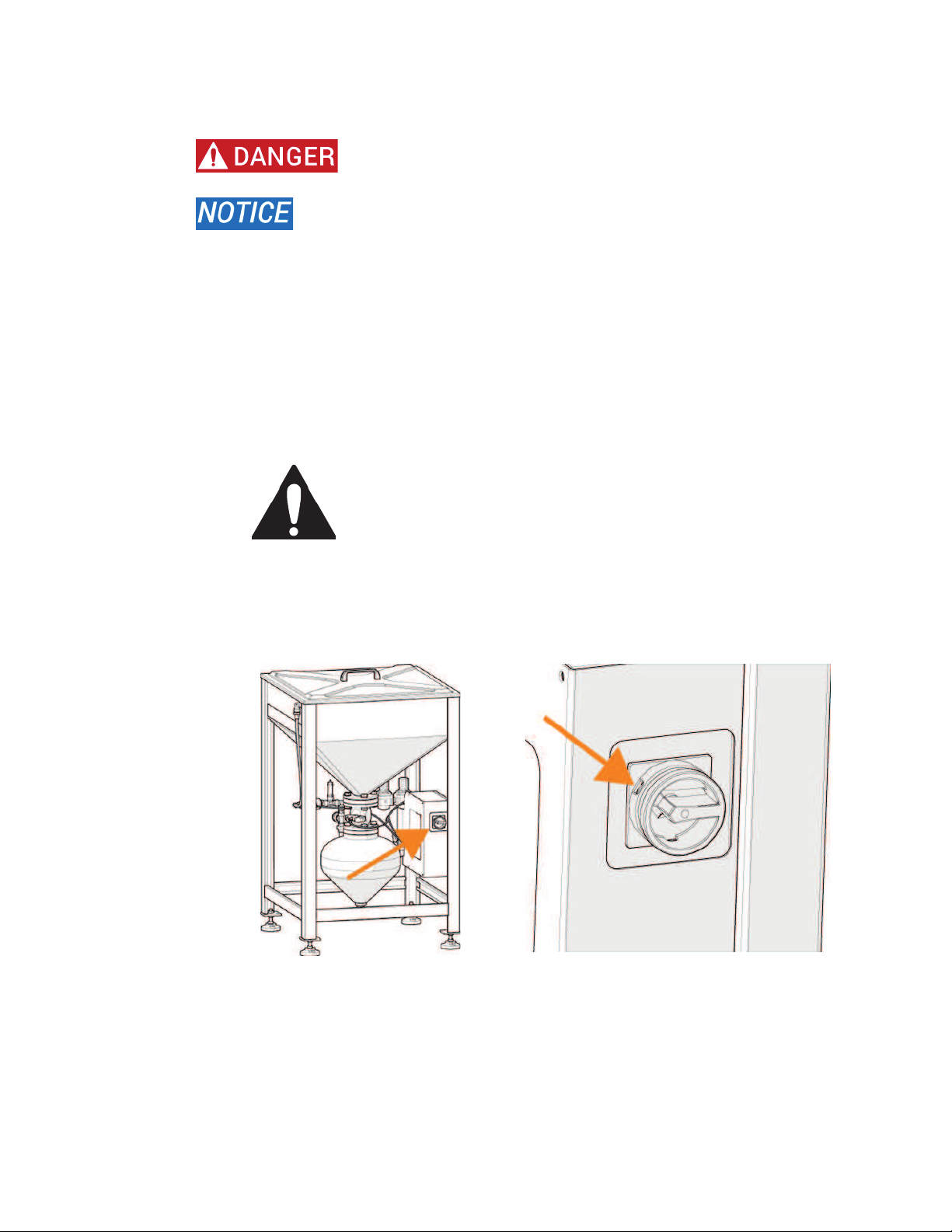
Customer air supply......................................................................... has lockout/tagout capability
Customer air supply line ........................................................................................ >20 mm (3/4 in.)
Operating pressure/volume ............................................ 5.5 bar (80 psi) @ 566 lpm (20 scfm)1
Surge pressure/volume....................................5.5–6.5 bar (80–94 psi) @ 2250 lpm (80 scfm)
Maximum compressed air volume.................. dependent on abrasive material and flow rate
Quality of compressed air........................................................................FT[CPFHKNVGTGFVQO
Supply voltage.......................................................................100–240 VAC, 50/60 Hz, or 24VDC2
AC Frequency.........................................................................................................................50/60 Hz
Full-Load current ................................................................................................... 0.20 A@ 240 VAC
.................................................................................................................................. 0.48 A @ 100 VAC
.......................................................................................................................................2.0 A @ 24 VDC
Largest-load current..................................................................................................................... 2.0 A
Rating (SCCR) ..............................................................................................................................2.5 kA
Site..................................................................................................................................Level and solid
Operating environment temperature..................................................... 0°C–55°C (32°F–131°F)
Operating environment relative humidity ..........................................................................5%–95%
Operating environment elevation................................. 0–2500 m (0–8200 ft) above sea level
Service clearance ................................................................................1 m (3 ft) on front and sides
1Requires a minimum of 2 bar (30 psi) difference between the supply pressure and the operating pressure.
© 2016–2017 Flow International Corporation
Page 6 of 31

Sound level, conveying abrasive........................................................................................69.6 dBa3
Sound level, depressurization ............................................................................................... 98 dBa3
Sound level, repressurization............................................................................................. 79.4 dBa3
Transport the ADS
Contact Flow Technical Service if you are connecting the ADS to a different voltage power
supply in the new location.
CAUTION! Comply with your local regulations for moving equipment. Flow
recommends the presence of flaggers and spotters.
1. Empty the silo.
WARNING! The silo must be empty to transport the ADS. If you
leave abrasive in the silo, it can cause an unsafe high center of
gravity during transport.
2. Disconnect the electrical and pneumatic connections.
3. Use a forklift or pallet jack to lift the ADS. Place the forks under a pair of lower
beams on the frame (accessible from all four sides). Transport it to the final
operating location.
4. Place the ADS on a level and solid foundation.
5. Level the ADS with the leveling pads.
6. If required, use anchor bolts to attach the ADS to the floor.
© 2016–2017 Flow International Corporation
Page 7 of 31

Components
The abrasive material is loaded through the sieve and temporarily stored in the silo. You
can fill the silo without stopping the ADS. Abrasive moves from the silo through a pinch
valve, and then to the vessel. The abrasive flows through a hose to the cutting system.
Visual and audio signals provide operating condition and warning notices. The control
cabinet display shows status messages.
There are two low abrasive switches:
Silo low abrasive switch. When this switch does not sense abrasive, it signals the
PLC to start the flashing warning indicator and rhythmic audio signal. The display
panel shows the “Silo Empty” message.
Vessel low abrasive switch. When this switch does not sense abrasive, it signals
the PLC to start the continuous warning indicator and continuous audio signal.
The display panel shows the “Vessel Empty” message. If you are using FlowCUT™,
the program stops.
Number Description
1
Lid
2
Sieve
3 Silo
4
Silo low abrasive switch
5
Control cabinet
6
Vessel low abrasive switch
7
Vessel
8 Pinch valve pneumatic
controls
© 2016–2017 Flow International Corporation
Page 8 of 31

Control cabinet
The control cabinet uses alternating current (AC) from 100 to 240V at 50/60Hz, or 24V
direct current (DC). The internal control voltage is 24V DC.
The control cabinet contains the PLC, terminal strip, and warning indicators.
The PLC constantly monitors the operating conditions and sends control signals to the
solenoid valves, the warning indicator, and the audio signal.
Number Description
1 Electrical hazard warning label
2 Yellow warning indicator
3 Audio signal
4 Display panel
5 CE label
6 Panel lock
© 2016–2017 Flow International Corporation
Page 9 of 31

Display panel
The display panel shows the following notices:
Notice Description
Filling Fill cycle
Bleed Release of the vessel pressure
Running Normal operation mode
Silo Empty Silo is empty
Vessel Empty Vessel is empty
Replace Insert of Pinch
Valve Reset P3 =>
Pinch valve hose insert replacement is necessary. This
service message shows after 6000 cycles.
Button Button ID Button function
P1
Push and hold the button for five seconds to show (from
top to bottom) the following: software version, operating
hours (h), switching cycles (c)
P2
Push this button to open the vent, venting valve, and
normally closed pressure solenoid valve to release
pressure from the vessel.
P3
Push and hold this button for five seconds to set the cycle
counter to zero.
P4
Push and hold this button for 10 seconds to switch the
potential free contacts for a warning message from
normally open to normally closed. You can accept the
selected signal in the ADS and use it there for an
additional alarm or as a way to stop the cutting process.
© 2016–2017 Flow International Corporation
Page 10 of 31

Warning indicators
The yellow warning indicator and the audio signal tells operators of specific conditions.
See the Troubleshooting section for more information.
Warning Cause Remedy
Yellow warning indicator
flashes and the audio signal
operates in a rhythmic
pattern. The device stays in
operation.
If the ADS integrates with
FlowCUT, a flashing warning
indicator displays on the
machine PC.
Silo abrasive level is low.
The silo low abrasive switch
signaled that the abrasive
level is at the minimum
level.
Fill the silo with abrasive.
Yellow warning indicator
illuminates continuously and
the audio signal sounds
continuously.
The vessel low abrasive
switch has not signaled the
presence of abrasive for 20
seconds.
The ADS is stopped. It
starts after the vessel fills
with abrasive.
Fill the silo with abrasive.
If applicable, start
FlowCUT again after the
warning indicators have
turned off.
© 2016–2017 Flow International Corporation
Page 11 of 31

Pneumatic controls
Symbol Definition Symbol Definition
CAS Customer Air Supply PS370 Pressure switch (when
used)
PR1 Pressure Regulator 1—
Set to 5.5 bar (80 psi) PV1 Pinch Valve 1—
Normally Open
PR2 Pressure Regulator 2—
Set to 2.7 bar (40 psi) PV2 Pinch Valve 2—
Normally Open
PS227 Abrasive ADS Low—
Normally Open (Warning) SOL351 Primary Pinch Valve
Control—Normally Open
PS219 Vessel Empty—
Normally Open (Warning) SOL319 Air Exhaust Pinch Valve
Control—Normally Closed
MSR
Main System Relief—
Factory set to 7 bar (100
psi)
SOL311 Air Supply Valve Control—
Normally Closed
GA1 Gauge 1 EX1 Exhaust 1
GA2 Gauge 2 EX2 Exhaust 2
GA3 Gauge 3 EX3 Exhaust 3
GA4 Gauge 4 EX4 Exhaust 4
© 2016–2017 Flow International Corporation
Page 12 of 31

The controls are:
Two pinch valves
Two pressure regulating valves
Two solenoid valves, normally closed (N/C)
One solenoid valve, normally open (N/O), for venting
One check valve
The supply pressure controls the pinch valve. The operating pressure controls the vessel.
A safety valve opens at 7 bar (102 psi) and limits the maximum pressure in the vessel.
Pinch valve PV1 is operated by compressed air. It is controlled by SOL351.
There must be a minimum of 2 bar (30 psi) difference between the supply pressure PR1
and the operating pressure PR2 to ensure closure of the pinch valve. For best
performance, set PR1 to 5.5 bar (80 psi) and PR2 to 2.8 bar (40 psi). If the minimum
difference is maintained, you can adjust PR1 and PR2 to control the abrasive flow.
Proximity switch PS219 sends a signal to the PLC to indicate presence of abrasive. If
there is no abrasive, the PLC sends a signal to release the pressure from the vessel, and
then sends a signal to open the pinch valve. When the proximity switch senses abrasive
during refilling, a delay timer starts. When the delay timer ends, the pinch valve closes,
and the vessel pressurizes.
When SOL319 opens pinch valve PV2, pressure is released from the vessel to the silo.
© 2016–2017 Flow International Corporation
Page 13 of 31

Operation
CAUTION! Never operate the ADS unless the abrasive outlet hose connects
to a cutting system.
Always keep the lid on, except when adding abrasive. The lid prevents abrasive from
spraying from the silo when the vessel releases pressure before entering the fill cycle.
If the ADS connects to a cutting system using FlowCUT, the cutting program stops when
the vessel switch signals the PLC. Start FlowCUT again after the indicators have reset.
Normal operation
This table describes the conditions of the switches, valves, and other components.
Switches Engaged State Disengaged State
Power switch The controller checks the state
of all switches and solenoids.
The controller waits for abrasive
to be added to the silo or starts
the steady state operating
cycle.
No pressure is supplied to the
vessel; the main pinch valve
opens. All controls/electronics are
without power.
Silo low abrasive
switch
The switch is engaged when it
senses abrasive.
The switch is disengaged when it
does not sense abrasive. The
yellow warning indicator flashes
and the rhythmic audio signal
operates.
Vessel low
abrasive switch
The switch is engaged when it
senses abrasive.
During a refill cycle, the switch
signals the pinch valve to close
and for the vessel to pressurize.
When the switch is disengaged,
the refill cycle starts.
If disengaged for approximately
20 seconds, the yellow warning
indicator turns on continuously
and the audio signal operates
continuously.
Pressure Switch
(Mach 4c only)
When engaged, the pressure
switch signals FlowCUT that the
vessel has air pressure.
When disengaged, FlowCUT
prevents any programs from
starting and stops any running
programs.
© 2016–2017 Flow International Corporation
Page 14 of 31

Fill the ADS
1. Remove the lid, and then fill the silo with abrasive.
CAUTION!
Wear safety goggles to prevent eye injuries caused by
pressurized abrasive leaking from the silo.
Wear a dust mask or respirator when loading abrasive
into the silo to prevent particle or dust inhalation.
Observe proper lifting techniques when lifting abrasive
bags.
Avoid adding abrasive near the pressure valve muffler
(below).
2. Put the lid on the silo.
© 2016–2017 Flow International Corporation
Page 15 of 31

Startup
1. Ensure the abrasive outlet hose connects to the vessel and the cutting system.
2. Ensure that the abrasive level is above the silo low abrasive switch.
3. Turn on the air supply to the ADS.
4. Ensure that the PR1 gauge is at 5.5 bar (80 psi) and PR2 is at 2.8 bar (40 psi).
5. Turn on the power switch.
Shutdown
Turn off the power switch.
© 2016–2017 Flow International Corporation
Page 16 of 31

Maintenance
Description Daily Other
Examine the pressure regulating valves, solenoid
valves, and check valve for damage.
Examine the solenoid valve on the pinch valve for
damage.
Examine the pressure gauges for functionality. There
must be a minimum difference of 2 bar (30 psi)
pressure between PR1 and PR2.
Replace the PV1 pinch valve seal. The display shows
a message when the pinch valve seal is due for
replacement.
Every 6000 cycles
Replace the silo low abrasive switch
PARTS
86200023, Proximity switch
TOOLS
6in. adjustable wrench
Small flat-tip screwdriver
TASK
1. Do the Lockout/Tagout procedure.
WARNING! Failure to do the lockout tagout procedure can result in
equipment damage or injury to personnel.
2. Remove abrasive until it is below the silo low abrasive switch.
3. Open the control panel, and then disconnect the cables from TB1-9, TB1-10, and
TB1-11.
© 2016–2017 Flow International Corporation
Page 17 of 31

4. Pull the cables out of the PS227 port.
5. Loosen the locknut, and then remove the proximity switch.
6. Remove abrasive from the silo threads.
Failure to remove all abrasive will damage the threads of the silo
and the proximity switch.
7. Install the new proximity switch. Turn the switch so that access to the adjustment
screw is easy. Tighten the locknut to hold the switch in position.
© 2016–2017 Flow International Corporation
Page 18 of 31

8. Insert the cables through the PS227 port, and then connect the cables:
Brown, 1142P to TB1-9
Blue, 1160N to TB1-10
Black 2270 to TB1-11
9. Fill the silo with abrasive, and then turn on the ADS.
10. Use the small flat-tip screwdriver to adjust the switch:
a. Turn the adjustment screw counterclockwise until it stops.
b. Turn the adjustment screw clockwise until the light on the switch comes
on.
c. Turn the adjustment screw counterclockwise until the light goes off.
d. Slowly turn the adjustment screw clockwise until the light comes on.
11. Connect the air supply to the ADS.
Replace the vessel low abrasive switch
PARTS
86200023, Proximity switch
TOOLS
6in. adjustable wrench
Small flat-tip screwdriver
TASK
1. Remove all abrasive from the vessel.
2. Do the Lockout/Tagout procedure.
WARNING! Failure to do the lockout tagout procedure can result in
equipment damage or injury to personnel.
3. Open the control panel, and then disconnect the cables from TB1-6, TB1-7, and
TB1-8.
© 2016–2017 Flow International Corporation
Page 19 of 31

4. Pull the cables out of the PS219 port.
5. Loosen the locknut, and then remove the low abrasive switch.
6. Remove the abrasive from the vessel threads.
Failure to remove all abrasive from the threads damages the
threads of the vessel and the switch.
7. Install the new switch. Turn the switch for easy access to the adjustment screw.
Tighten the locknut to hold the switch in position.
© 2016–2017 Flow International Corporation
Page 20 of 31
Table of contents
Other Flow Industrial Equipment manuals
Popular Industrial Equipment manuals by other brands

Grinnell
Grinnell G-FIRE 579 manual

Rexel
Rexel R750 instruction manual

Meritor
Meritor RS-220 Maintenance manual

Samoa
Samoa EXTRACTOR 70 Parts and technical service guide

SCHUNK
SCHUNK GWB 34 Assembly and operating manual

Stuart Turner
Stuart Turner MAINSBOOST iBOOST F200 Installation, operation & maintenance instructions