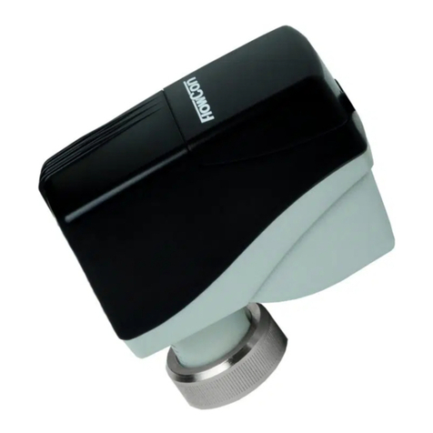
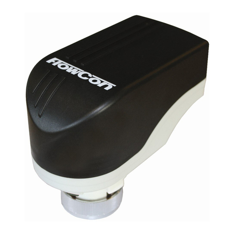
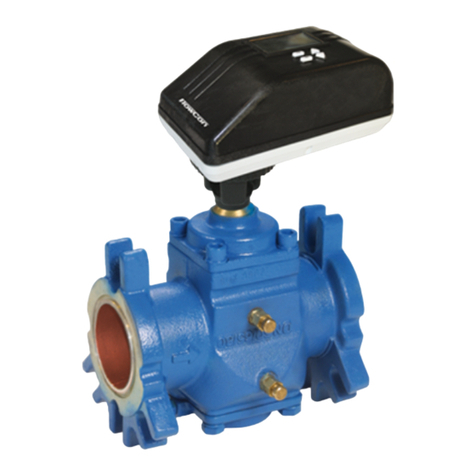
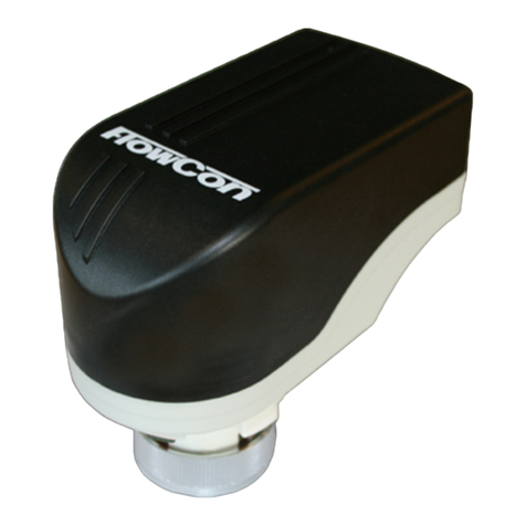
FlowCon FN.0.2 Owner's manual

Installation and Operation Instruction
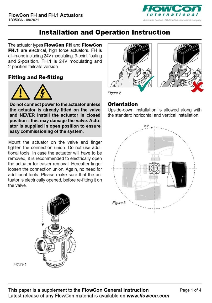
Figure 1
Figure 2
360º
Figure 3
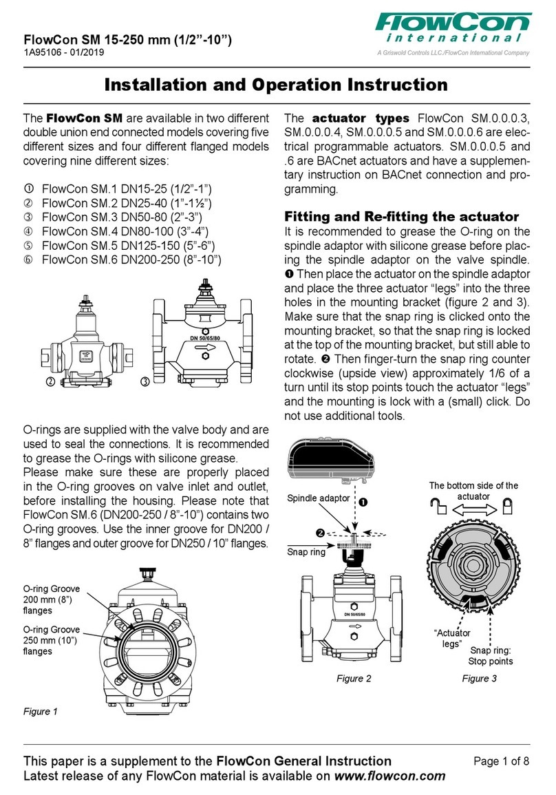
The actuator types FlowCon FN.0.2, FN.0.2-
BUS
and
FN.0.4
are electrical actuators.
•FN.0.2 is 24V modulating.
• FN.0.2-BUS is 24V modulating with Modbus or
BACnet communication.
• FN.0.4 is 24V 3-point floating and 2-position.
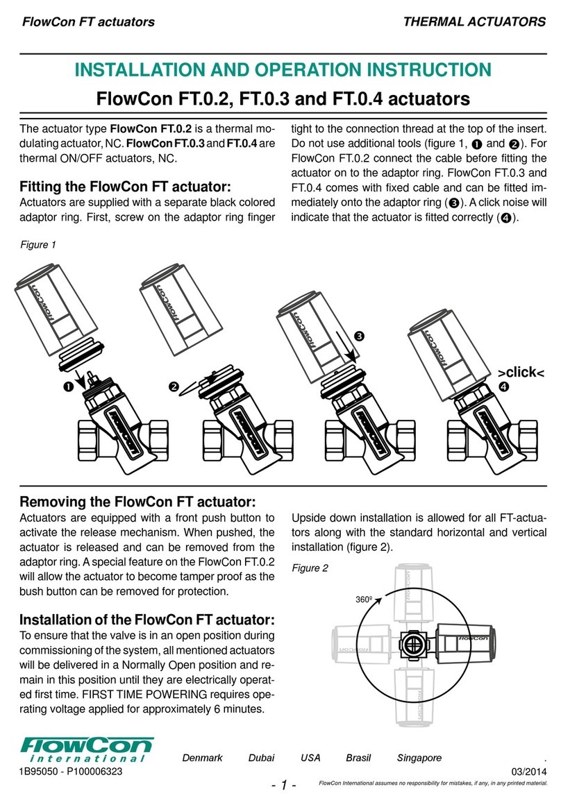
Fitting and Re-tting
Do not connect power to the actuator unless
the actuator is already fitted on the valve
and NEVER install the actuator in closed
position - this may damage the valve. Actu-
ator is supplied in open position to ensure
easy commissioning of the system.
Mount the actuator on the valve and finger
tighten the connection union. Do not use addi-
tional tools.
In case the actuator will have to be removed, it is
recommended for FN.0.2 and FN.0.4 to electri-
cally open the actuator by activating DIP switch
#6 for easier removal.
For FN.0.2-BUS set DIP switch #1-6 to OFF and
wait until the LED indicator is blinking green.
Hereafter, disconnect power and finger loosen
the connection union. Again, no need for addi-
tional tools. Please make sure that the actuator
is electrically opened, before re-fitting it on the
valve.
Orientation
Upside-down installation is allowed along with
the standard horizontal and vertical installation.
FlowCon FN.0.2, FN.0.2-BUS and FN.0.4
1B95080 - 01/2023
This paper is a supplement to the FlowCon General Instruction
Latest release of any FlowCon material is available on www.owcon.com
Page 1 of 8
FlowCon International assumes no responsibility for mistakes, if any, in any printed material.

Blue
Yellow
Power 24V AC/DC
Ground/common
Green
Grey
Feedback signal
0(2)-10V DC
Signal ground
Input signal
0(2)-10V DC
<0.5mA
Brown
FN.0.2 Actuator
0(2)-10V modulating
FlowCon FN (analog)
Black
Pink
Power 24V AC/DC
Ground/common
Yellow
D+
Red
FN.0.2-BUS Actuator
RS-485 Serial
Green
Violet
D-
White
Grey
P1 P2
FlowCon FN (digital)
Blue
Power 24V AC/DC
Ground/common
Grey
Brown
Open
FN.0.4 Actuator
2-Position, Normally Closed
Close
PLEASE NOTE: FN.0.4 has a reation time of 0.8 sec.
This is the time from giving a 24V power signal until
the actuator starts to move. This is particular important
if using apulse power signal.
Blue
Power 24V AC/DC
Ground/common
Grey
Brown
Open
Stop
FN.0.4 Actuator
3-Point Floating, Normally Closed
Close
Wiring
This paper is a supplement to the FlowCon General Instruction
Latest release of any FlowCon material is available on www.owcon.com
FlowCon FN.0.2, FN.0.2-BUS and FN.0.4
1B95080 - 01/2023
Page 2 of 8

Start-up Sequence
When power to the actuator is turned on, the
actuator will automatically calibrate to determine
closing point. Hereafter it will proceed to normal
operation mode (according to control signal).
For FN.0.2-BUS, bus address configuration is
required and must be done immediate after first
power on. Calibration mode and then normal op-
eration mode will follow thereafter.
Auto Cycle Sequence
Auto Cycle can be activated during commission-
ing. It prevents the valve from jamming when
the valve is not moved for a longer period of
inactivity. For FN.0.2 and FN.0.4 Auto Cycle is
activated by moving DIP switch #1 from OFF to
ON. The actuator will then perform 50% stroke
cycle every 3 weeks if not stroke movement has
occurred.
For FN.0.2-BUS Auto Cycle is activated and cy-
cle time configured via the bus (Modbus register
136 and BACnet AV.10; 0= not activated).
Override
For FN.0.2 and FN.0.4 electrical override is acti-
vated by moving DIP switch #6 from OFF to ON.
Then the valve will open fully. During override
mode the LED indicator will blink red and green.
When DIP switch #6 is moved back to OFF, the
actuator will re-calibrate and thereafter go into
normal operation mode. Electrical override is
performed with power supply on.
When performing the manually override proce-
dure on the FN.0.2-BUS, set DIP switches 1 to
6 to OFF and the spindle will fully retract, and
the LED will rapidly blink green. In this state the
valve can be manually close or opened using a
magnet.
To extend actuator spindle and fully close the
valve, briefly swipe the magnet along the right-
hand side of the actuator (top view and wires
downwards). LED indicator is blinking yellow
during this ‘manual spindle adjustment’ mode. To
retract the actuator spindle and open the valve
fully (mounting position), again briefly swipe the
magnet along the right-hand side of the actuator.
LED is blinking rapidly green to indicate ‘mount-
ing position’ mode. Manually override can be re-
peated as often as necessary.
Flush Mode (FN.0.2-BUS)
The automatic Flush Mode is activated and
cycle time configured via the bus (Modbus reg-
ister 132 and BACnet AV.35; 0= not activated).
In Flush Mode, the valve is temporarily fully
opened independent of the control signal to al-
low easy system flushing.
FlowCon FN.0.2, FN.0.2-BUS and FN.0.4
1B95080 - 01/2023
This paper is a supplement to the FlowCon General Instruction
Latest release of any FlowCon material is available on www.owcon.com
Page 3 of 8

DIP
switch Function ON Function OFF
#6 Electrical override ON Electrical override OFF
#5 No function No function
#4 Equal percentage Linear
#3 Normally Open Normally Closed
#2 Control signal 2-10V Control signal 0-10V
#1 Auto cycle ON Auto cycle OFF
6
5
4
3
2
1
%%
%%
%%
%%
%%
%%
%%
%%
%%
%%
DIP
switch Function ON Function OFF
#8 Terminal resistor active Terminal resistor inactive
#7 Modbus BACnet
#6 BIT 5 = 1 BIT 5 = 0
#5 BIT 4 = 1 BIT 4 = 0
#4 BIT 3 = 1 BIT 3 = 0
#3 BIT 2 = 1 BIT 2 = 0
#2 BIT 1 = 1 BIT 1 = 0
#1 BIT 0 = 1 BIT 0 = 0
6
5
4
3
2
1
8
7
Modbus
Address
setting Address
setting
BACnet
Modbus
Address
setting Address
setting
BACnet
Modbus BACnet
1
1
1
1
1
1 0
0
0
0
0
0
DIP Switch Settings
The valve functions are set on DIP switches found under the connection cover. PCB mounted electri-
cal components will not be directly exposed when DIP switches are to be set. Factory setting for all
switches is OFF.
FlowCon FN.0.2 Actuator
FlowCon FN.0.2-BUS Actuator
This paper is a supplement to the FlowCon General Instruction
Latest release of any FlowCon material is available on www.owcon.com
FlowCon FN.0.2, FN.0.2-BUS and FN.0.4
1B95080 - 01/2023
Page 4 of 8

DIP
switch Function ON Function OFF
#6 Electrical override ON Electrical override OFF
#5 No function No function
#4 No function No function
#3 Normally Open Normally Closed
#2 No function No function
#1 No function No function
6
5
4
3
2
1
%%
%%
%%
%%
FlowCon FN.0.4 Actuator
FN.0.2 FN.0.2-BUS FN.0.4
Normal operation mode Full on green Full on green Full on green
Charging mode (60 sec) n/a n/a n/a
Calibration mode
(closing point adjustment) Blinking green Blinking green Blinking green
Bus communication mode n/a Flickering green n/a
Mounting position mode n/a Rapid blinking green n/a
Electrical override mode Blinking red/green n/a Blinking red/green
Failsafe mode n/a n/a n/a
Manuel spindle adjustment n/a Blinking yellow n/a
Perpetual failure mode Full on red Full on red Full on red
LED Status
The LED indicator is visible through the dark colored transparent connection cover.
The LED indication will give the following statuses.
FlowCon FN.0.2, FN.0.2-BUS and FN.0.4
1B95080 - 01/2023
This paper is a supplement to the FlowCon General Instruction
Latest release of any FlowCon material is available on www.owcon.com
Page 5 of 8

Re-Calibration
FN.0.2
Re-calibration can be achieved in one of 2 ways:
1. Forced individual actuator re-calibration can also be performed by flipping DIP switch #6
from OFF to ON and back to OFF on the relevant actuator.
2. Forced concurrent re-calibration for all modulating actuators is electrically possible. Within 60
sec. provide the following electrical control signal sequence to the grey wire: 10V-2V-10V-2V-
10V-2V to achieve re-calibration.
After re-calibration the actuator will go into normal operation mode.
FN.0.2-BUS
For FN.0.2-BUS change MSV.1 to 2 (BACnet) or register 138 to 1 (Modbus).
After re-calibration the actuator will go into normal operation mode.
FN.0.4
Forced individual actuator re-calibration can also be performed by flipping DIP switch #6 from OFF
to ON and back to OFF on the relevant actuator.
After re-calibration the actuator will go into normal operation mode.
This paper is a supplement to the FlowCon General Instruction
Latest release of any FlowCon material is available on www.owcon.com
FlowCon FN.0.2, FN.0.2-BUS and FN.0.4
1B95080 - 01/2023
Page 6 of 8

BUS programming of
FlowCon FN.0.2-BUS
When using FN.0.2-BUS actuator and BUS
communication, setting on the Green/GreEQ in-
sert MUST BE be 5.0.
In this instruction default values are underlined.
Please see FlowCon FN.0.2-BUS Modbus Data
Point List or BACnet PICS for more detailed in-
formation.
Initiate by setting Baud Rate (register 105 or
MSV.7). Set actuator DIP switches 1-6 to write-
able mode, i.e. 1-1-1-1-1-1-1 and set MAC Ad-
dress via bus communication (register 104 or
AV.28) and proceed by selecting your PICV
valve in register 110 or MSV.8:
Reg. 110 MSV.8 Selected valve
0 1 (generic linear)
1 2 Green.0
2 3 Green.1
3 4 Green.2
4 5 Green.1HF
5 6 GreEQ.0
6 7 GreEQ.1
7 8 GreEQ.2
8 9 (generic EQ%)
9 10 user-valve
And select your PICV control mode in register
103 or MSV.13:
Reg. 103 MSV.13 Selected control mode
0 0 (linear)
1 1 Equal%
Set Operating Mode in register 200=0 or
MSV.4=1 and provide Control Signal in register
400 or AV.1 (0% to 100%).
Condition of the FN.0.2-BUS
through BUS
Check the Current Flow (not measured) in
register 402 or AI.7.
Status Information is available in BI.3 and
Error Information is available in BI.4, BI.5,
BI.6 and BI.7. This is combined for Modbus in
register 318 and 407.
Service Commands and resetting is avail-
able in register 138 or MSV.1
FlowCon FN.0.2, FN.0.2-BUS and FN.0.4
1B95080 - 01/2023
This paper is a supplement to the FlowCon General Instruction
Latest release of any FlowCon material is available on www.owcon.com
Page 7 of 8
This manual suits for next models
2
Table of contents
Other FlowCon Controllers manuals

