manuals.online logo
Brands
  1. Home
  2. •
  3. Brands
  4. •
  5. FlowCon
  6. •
  7. Controllers
  8. •
  9. FlowCon FH Owner's manual

FlowCon FH Owner's manual

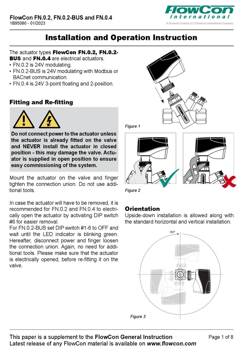
Installation and Operation Instruction
Figure 1
360º
Figure 3
Figure 2
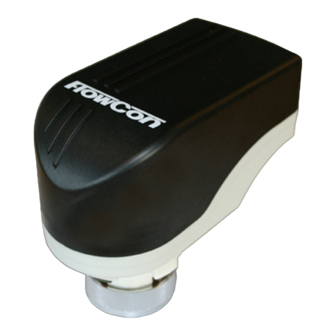
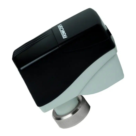
The actuator types FlowCon FH and FlowCon
FH.1 are electrical, high force actuators. FH is
all-in-one including 24V modulating, 3-point floating
and 2-position. FH.1 is 24V modulating and
2-position failsafe version.
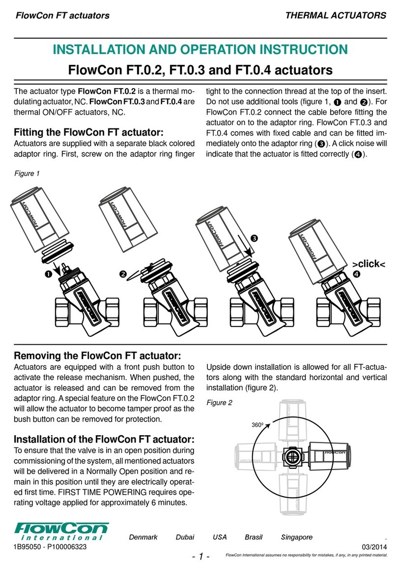
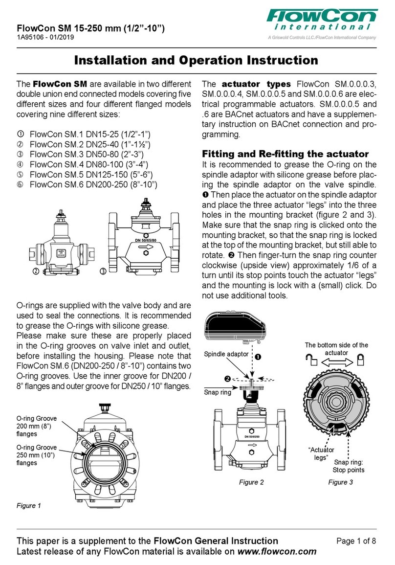
Fitting and Re-tting
Do not connect power to the actuator unless
the actuator is already fitted on the valve
and NEVER install the actuator in closed
position - this may damage the valve. Actu-
ator is supplied in open position to ensure
easy commissioning of the system.
Mount the actuator on the valve and finger
tighten the connection union. Do not use addi-
tional tools. In case the actuator will have to be
removed, it is recommended to electrically open
the actuator for easier removal. Hereafter finger
loosen the connection union. Again, no need for
additional tools. Please make sure that the ac-
tuator is electrically opened, before re-fitting it on
the valve.
Orientation
Upside-down installation is allowed along with
the standard horizontal and vertical installation.
FlowCon FH and FH.1 Actuators
1B95036 - 09/2021
This paper is a supplement to the FlowCon General Instruction
Latest release of any FlowCon material is available on www.owcon.com
Page 1 of 4
FlowCon International assumes no responsibility for mistakes, if any, in any printed material.

Blue
Yellow
Power 24V AC/DC
Ground/common
Green
Grey
Feedback signal
0(2)-10V DC
Signal ground
Input signal
0(2)-10V DC
<0.5mA
Brown
FH / FH.1 Actuator
0(2)-10V modulating
Blue
Power 24V AC/DC
Ground/common
Grey
Open
Stop
FH / FH.1 Actuator
3-Point Floating, Normally Closed
Brown
Close
Yellow
Signal ground
Green
Feedback signal
0(2)-10V DC
Blue
Power 24V AC/DC
Ground/common
Grey
Brown
Open
FH / FH.1 Actuator
2-Position, Normally Closed
Close
Yellow
Green
Feedback signal
0-10V DC
Signal ground
FlowCon FH (analog)
FlowCon FH (digital)
Wiring
Start-up Sequence
When power to the actuator is turned on, the
actuator will automatically calibrate to determine
closing point. Hereafter it will proceed to normal
operation mode (according to control signal).
For the failsafe version (FH.1), capacitor charg-
ing will be prioritized (max. 215 sec depending
on capacitor energy level) during start-up and
re-powering. After completion of charging mode
followed by calibration mode, the actuator will
proceed to normal operation mode.
Auto Cycle Sequence
Auto Cycle can be activated during commis-
sion
ing. It prevents the valve from jamming when
the valve is not moved for a longer period of in-
activity. By moving DIP switch #1 from OFF to
ON, Auto Cycle is activated. Actuator will then
perform 50% stroke cycle
every 3 weeks if no
stroke
movement has occured.
Re-Calibration (FlowCon FH)
By flipping DIP switch #6 from one setting to the
other (starting position indifferent) re-calibration
is activated. After completed re-calibration the
actuator will automatically go into normal ope-
ration. During re-calibration mode the LED will
blink green.
Manual Override (FlowCon FH)
Before performing manual override, please turn
off the power supply. Lift the silicone cap on the
top of the actuator to get access to manual over-
ride. Manual override is performed by a 4 mm
(~5/32”) hex key. Clockwise turning will open the
valve and counter-clockwise turning will close
the valve.
Electrical Override (FlowCon FH.1)
By moving DIP switch #6 from OFF to ON, elec-
trical override is activated and the actuator will
open valve fully. During electrical override the
LED indicator will blink red and green. When DIP
switch #6 is moved back to OFF, the actuator will
re-calibrate and thereafter go into normal opera-
tion mode. Electrical override is performed with
power supply on.
Failsafe Mode (FlowCon FH.1)
When power is lost, the actuator will go into fail-
safe mode after a few seconds, mandatory that
capacitor charging and start-up sequence are
completed. The actuator will perform failsafe ac-
tion (open or close) and stay in failsafe final posi-
tion until return of power. Upon power, the actua-
tor remains in the final failsafe position until charg-
ing mode is reached (max. 215 sec). Hereafter the
actuator will return to normal operation mode.
This paper is a supplement to the FlowCon General Instruction
Latest release of any FlowCon material is available on www.owcon.com
FlowCon FH and FH.1 Actuators
1B95036 - 09/2021
Page 2 of 4
FlowCon FH Actuator
DIP
switch Function ON Function OFF
#6 Re-calibration Re-calibration
#5 No function No function
#4 Equal percentage Linear
#3 Normally Open Normally Closed
#2 Control signal 2-10V Control signal 0-10V
#1 Auto cycle ON Auto cycle OFF
6
5
4
3
2
1
%%

%%

%%

%%

%%

%%

%%

%%

%%

%%

FlowCon FH.1 Actuator
DIP
switch Function ON Function OFF
#6 Electrical override ON Electrical override OFF
#5 Failsafe open Failsafe close
#4 Equal percentage Linear
#3 Normally Open Normally Closed
#2 Control signal 2-10V Control signal 0-10V
#1 Auto cycle ON Auto cycle OFF
6
5
4
3
2
1
% %
% %
% %
% %
% %
% %
% %
% %
% %
% %
% %
% %
DIP Switch Settings
The valve functions are set on DIP switches found under the connection cover. PCB mounted electri-
cal components will not be directly exposed when DIP switches are to be set. Factory setting for all
switches is OFF.
FlowCon FH and FH.1 Actuators
1B95036 - 09/2021
This paper is a supplement to the FlowCon General Instruction
Latest release of any FlowCon material is available on www.owcon.com
Page 3 of 4
FH FH.1
Normal operation mode Full on green Full on green
Charging mode (200 sec) n/a Blinking red
Calibration mode (closing point adjustment) Blinking green Blinking green
Electrical override mode n/a
Blinking red/green
Failsafe mode n/a OFF
Perpetual failure mode Full on red Full on red
LED Status
The LED indicator is visible through the dark
colored transparent connection cover. The LED
indication will give the following statuses.
Re-Calibration
Re-calibration can be achieved in one of 2 ways:
1. Forced individual actuator re-calibration can
also be performed by flipping DIP switch #6
from OFF to ON and back to OFF on the rele-
vant actuator.
2. Forced concurrent re-calibration for all actua-
tors is electrically possible. Within 60 sec.
provide the following electrical control signal
sequence to the grey wire: 10V-2V-10V-2V-
10V-2V to achieve re-calibration.
After re-calibration the actuator will go into normal
operation mode.
This paper is a supplement to the FlowCon General Instruction
Latest release of any FlowCon material is available on www.owcon.com
FlowCon FH and FH.1 Actuators
1B95036 - 09/2021
Page 4 of 4
FlowCon International assumes no responsibility for mistakes, if any, in any printed material.

This manual suits for next models

1

Other FlowCon Controllers manuals

FlowCon SM Series Owner's manual

FlowCon

FlowCon SM Series Owner's manual

FlowCon FN.1.4 Owner's manual

FlowCon

FlowCon FN.1.4 Owner's manual

FlowCon FN.0.3 Owner's manual

FlowCon

FlowCon FN.0.3 Owner's manual

FlowCon SM.3 Owner's manual

FlowCon

FlowCon SM.3 Owner's manual

FlowCon FN.0.2 Owner's manual

FlowCon

FlowCon FN.0.2 Owner's manual

FlowCon FN.0.2 Owner's manual

FlowCon

FlowCon FN.0.2 Owner's manual

FlowCon FT.0.3 Owner's manual

FlowCon

FlowCon FT.0.3 Owner's manual

Popular Controllers manuals by other brands

Zamel exta MOM-02 instruction manual

Zamel

Zamel exta MOM-02 instruction manual

Siemens SIRIUS 3RW40 5 Original operating instructions

Siemens

Siemens SIRIUS 3RW40 5 Original operating instructions

Watersports Innovations The Boost Box WS 1107 Installation & operation instructions

Watersports Innovations

Watersports Innovations The Boost Box WS 1107 Installation & operation instructions

Panasonic EYFRZ01 operating instructions

Panasonic

Panasonic EYFRZ01 operating instructions

Seltron ACD20 instruction manual

Seltron

Seltron ACD20 instruction manual

SOLOMON SYSTECH SSD1331 Technical data

SOLOMON SYSTECH

SOLOMON SYSTECH SSD1331 Technical data

Trane Symbio 210 Installation, operation and maintenance

Trane

Trane Symbio 210 Installation, operation and maintenance

Cardinal CLiC WD-02.1.4 installation manual

Cardinal

Cardinal CLiC WD-02.1.4 installation manual

Vestax VMC-185XL Service note

Vestax

Vestax VMC-185XL Service note

Danfoss VLT FC Series Spare Brake IGBT installation instructions

Danfoss

Danfoss VLT FC Series Spare Brake IGBT installation instructions

Multiplex MULTIcont BL-20 SD instructions

Multiplex

Multiplex MULTIcont BL-20 SD instructions

Silicon Laboratories UG268 user guide

Silicon Laboratories

Silicon Laboratories UG268 user guide

marklin Central Station Series manual

marklin

marklin Central Station Series manual

Elko LIC-1 manual

Elko

Elko LIC-1 manual

ComAp InteliLite NT AMF Series reference guide

ComAp

ComAp InteliLite NT AMF Series reference guide

Alltrax DCX300-ET manual

Alltrax

Alltrax DCX300-ET manual

TECHCON SYSTEMS TS550R user guide

TECHCON SYSTEMS

TECHCON SYSTEMS TS550R user guide

LSI MegaRAID SCSI 320-2E Quick Hardware Setup Guide

LSI

LSI MegaRAID SCSI 320-2E Quick Hardware Setup Guide

manuals.online logo
manuals.online logoBrands
  • About & Mission
  • Contact us
  • Privacy Policy
  • Terms and Conditions

Copyright 2025 Manuals.Online. All Rights Reserved.