FlowMotion 2001V Series User manual

2001V Series
Peristaltic Chemical Feed Pump


Installation and Operation Manual
2001V
Peristaltic Chemical Feed Pump
July 2020
Flomotion Systems, Inc.
3 N Main St, Middleport, NY 14105
Toll Free: (800)909-3569 (U S & Canada)
Tel: (716)691-3941
Fax: (716)691-1253
info@flomotionsystems com
www flomotionsystems com

TABLE OF CONTENTS
1 0 - System Overview 5
1.1 SAFETY...............................................................................................................................................................................................5
1.2 WARRANTY.........................................................................................................................................................................................5
1.3 RECEIVING..........................................................................................................................................................................................6
1.4 CUSTOMER MODIFICATION...................................................................................................................................................................6
1.5 INFORMATION FOR RETURNING PUMPS ................................................................................................................................................6
2 0 – 2001V Series Pump and Pumphead 7
2.1 TUBING, SPINDLE AND COVER INSTALLATION.......................................................................................................................................8
2.2 MOUNTING PUMP ON GEARBOX, INSTALLATION OF COLLET.................................................................................................................
2.3 PUMP MOUNTING AND COLLET INSTALLATION PROCEDURE................................................................................................................10
2.4 HOSE AND ROLLER INSTALLATION.....................................................................................................................................................10
2.5 TUBING & CONNECTIONS...................................................................................................................................................................16
3 0 – 2001V Series Gearbox 18
3.1 RUN-IN PERIOD.................................................................................................................................................................................18
3.2 MAINTENANCE..................................................................................................................................................................................18
3.3 2001V SERIES MOTOR / GEARBOX SPECIFICATIONS ..........................................................................................................................18
3.4 2001V SERIES POWER & MOTOR WIRING.........................................................................................................................................18
4 0 – 2001V Series Drive Controller 20
4.1 OPERATION AND WIRING...................................................................................................................................................................20
4.2 PROGRAMMING .................................................................................................................................................................................20
4.3 MANUAL SPEED / AUTO SPEED / RESTART TOGGLE SWITCH...............................................................................................................20
5 0 - 2001 Series Tubing Rupture Detector 21
5.1 ALARM CAUSES.................................................................................................................................................................................21
5.2 WHAT TO DO IN AN ALARM CONDITION...............................................................................................................................................21
5.3 RESETTING THE ALARM......................................................................................................................................................................21
5.4 RESUMING SERVICE...........................................................................................................................................................................21
5.5 INTERFACING.....................................................................................................................................................................................22
5.6 CALIBRATION....................................................................................................................................................................................22

1 0 - System Overview
The 2001V Chemical Feed Pump consists of a controller, motor, gearbox and peristaltic pump
1.1 Safety
In the interests of safety, this pump and the tubing selected should only be used by competent, suitably trained
personnel after they have read and understood this manual, and considered any hazard involved Any person
who is involved in the installation or maintenance of this equipment should be fully competent to carry out the
work
Maintenance and repair should be performed by qualified personnel only. Make sure that no
voltage is applied while work is being carried out on the pump or motor. The motor must be
secured against accidental start up.
1.2 Receiving
Inspect all cartons for damage, which may have occurred during shipping Carefully unpack equipment and
inspect thoroughly for damage or shortage Report any damage to carrier and/or shortages to supplier All
major components and connections should be examined for damage and tightness, with special attention given
to PC boards, plugs, knobs and switches
1.3 Customer Modification
Flomotion Systems, Inc , its sales representatives and distributors, welcome the opportunity to assist our
customers in applying our products Many customizing options are available to aid in this function Flomotion
Systems, Inc cannot assume responsibility for any modifications not authorized by its engineering department
1.4 Information for Returning Pum s
Equipment that has been contaminated with, or exposed to, body fluids, toxic chemicals or any other
substance hazardous to health must be decontaminated before it is returned to Flomotion Systems or its
distributor A certificate included at the rear of these operating instructions, or signed statement, must be
attached to the outside of the shipping container This certificate is required even if the pump is unused If the
pump has been used, the fluids that have been in contact with the pump and the cleaning procedure must be
specified along with a statement that the equipment has been decontaminated
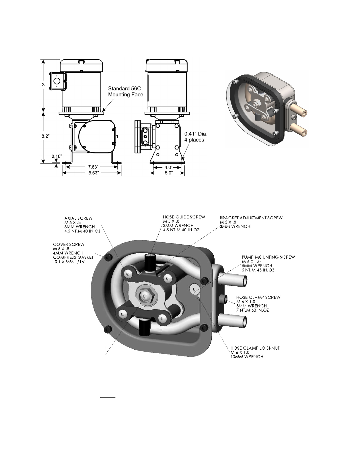
2 0 – 2001V Series Pump and Pumphead
The 2001 Series pumphead has two spring-loaded working rollers, which automatically compensate for minor
variations in tubing wall thickness, giving extended tube life
IMPORTANT: The 2001V Series is equi ed with a um cover for safety and rotection against
chemical s ills. The cover must be installed whenever the um is in use.
ROLLER ASSEMBLY
COLLET SCREW
4MM HEX WRENCH
7 NT M 60 IN OZ
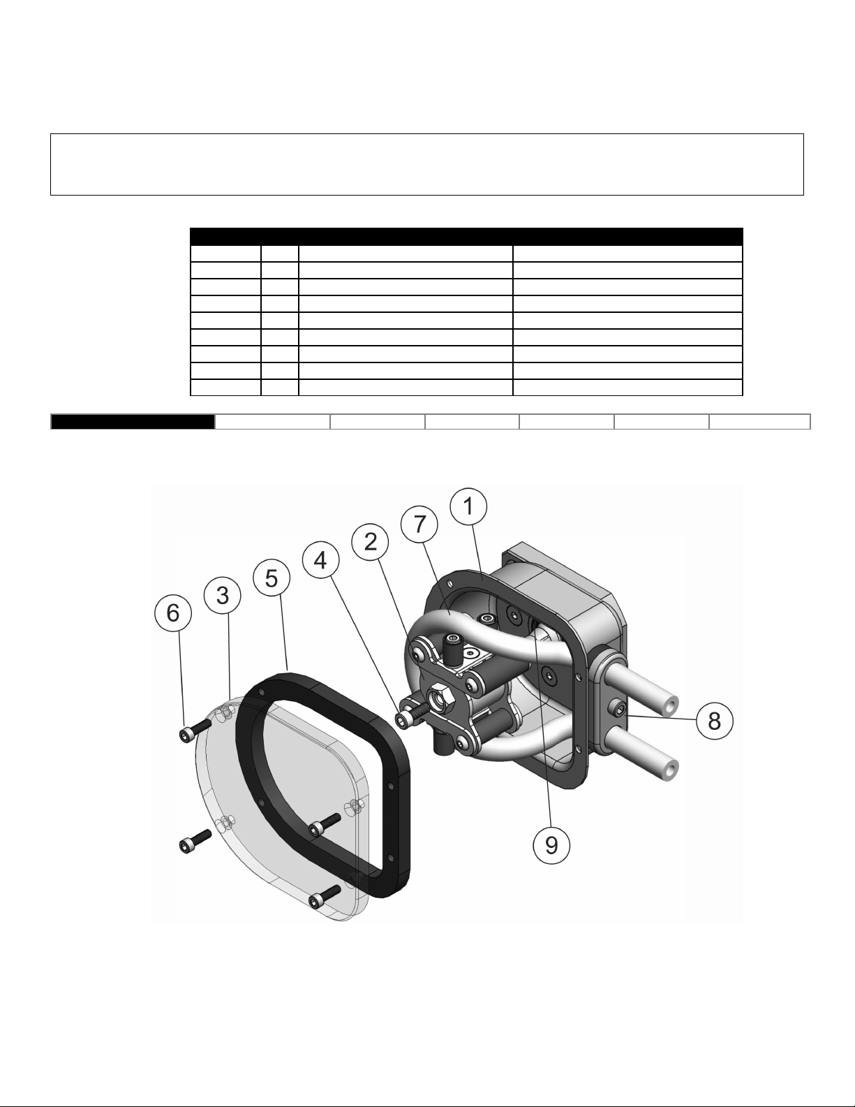
2 1 Tubing, Spindle and Cover Installation
! IMPORTANT: Disconnect um controller from ower su ly BEFORE changing tubing!
Item No Qty Part No Description
1 1 n/a Pump Collet & Hose Assy
2 1 100329 Roller Assembly
3 1 100330 Cover
4 1 100324 Collet Screw
5 1 100305C Cover Gasket
6 4 100307C Cover Screw
7 1 n/a Tube
8 1 Varies with tubing selection* Tube Seal
9 1 Shaft Seal 10x28x7 Shaft Seal
*Tube Seal PN 100329 100330 100331 100332 100333 100334
Hose is shown bent forward out of the pump housing to illustrate the correct hose
and roller assembly position, prior to sliding the hose and spindle into the housing
and over the collet

2.2 Mounting Pum on Gearbox, Installation of Collet
Item No Qty Part No Description
1 1 NA Pump Housing with Tube Seal
2 1 100306 Collet
3 2 100330 Pump Mounting Screws
4 1 NA Tubing
2.3 Pum Mounting and Collet Installation Procedure
1 To install the pump housing on the gearbox, slide it over the central pilot on the gearbox adaptor plate
Next install and torque the mounting screws to 5 NT M (45 in oz)
2 Next install the collet on the gearbox shaft There is a slot in the collet that the flat drive tang on the
gearbox shaft must slide into Orient the collet to allow the drive tang to slide into the slot and push the
collet completely onto the gearbox shaft When the collet bottoms out it is in the correct position
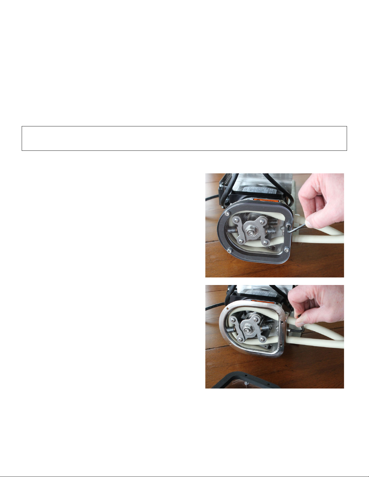
2.4 Hose and Roller Installation
! IMPORTANT: Disconnect um controller from ower su ly BEFORE changing tubing!
Make sure um suction and discharge lines are com letely drained and isolated.
Note that the hose seal size must match the selected tubing size.
Disassembly:
1. Remove four (4) 4mm pump cover screws
2. Loosen Tube Seal Clamp Screw with 5mm hex wrench
3. Remove 5mm collet screw
4. Remove the roller assembly
5. Remove worn pump tubing from pumphead
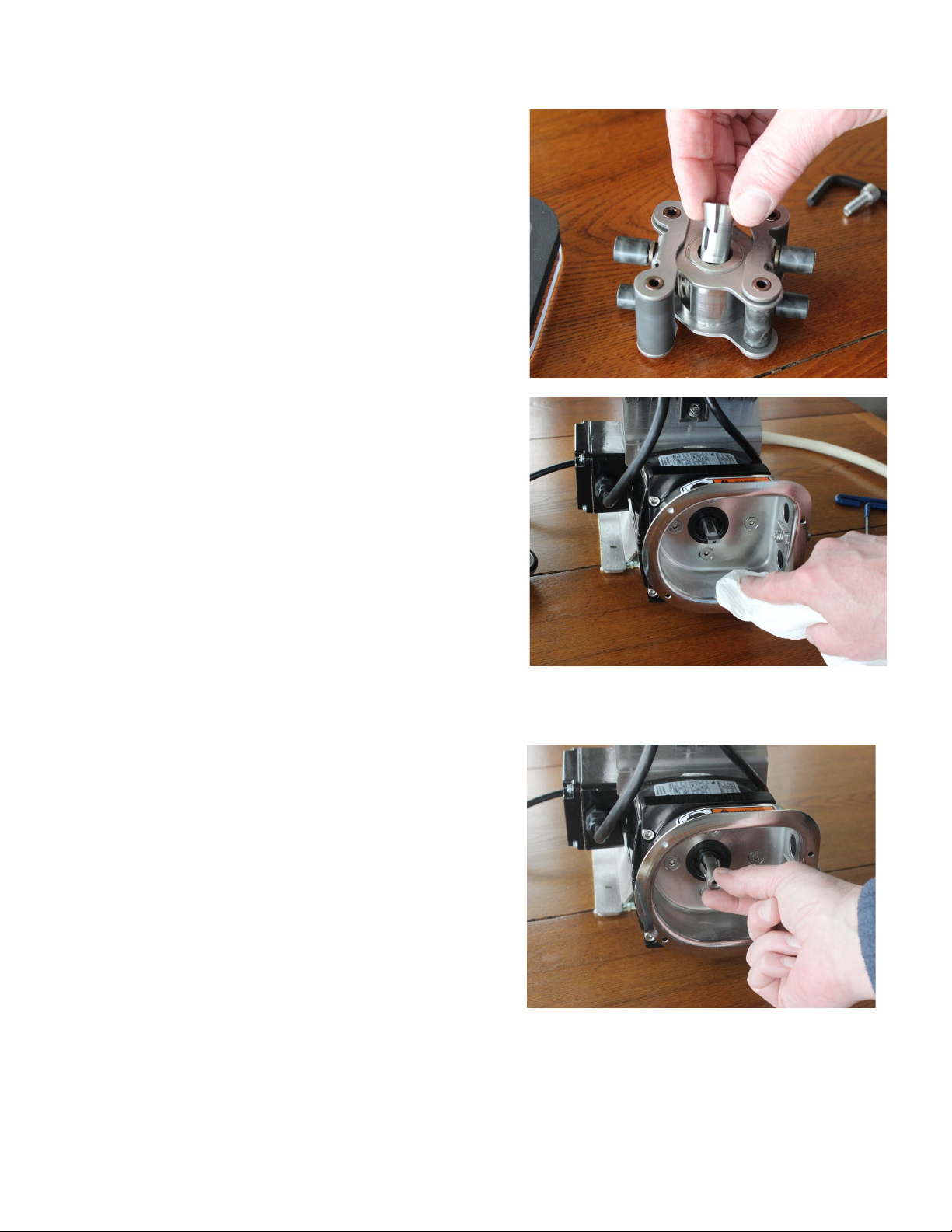
6. Remove and inspect collet for wear Note that the collet
may remain in the roller assembly when the roller
assembly is removed from the pump shaft
7. Clean inside of pump housing with damp rag or an
appropriate cleaning solution to remove any chemical or
tubing residue
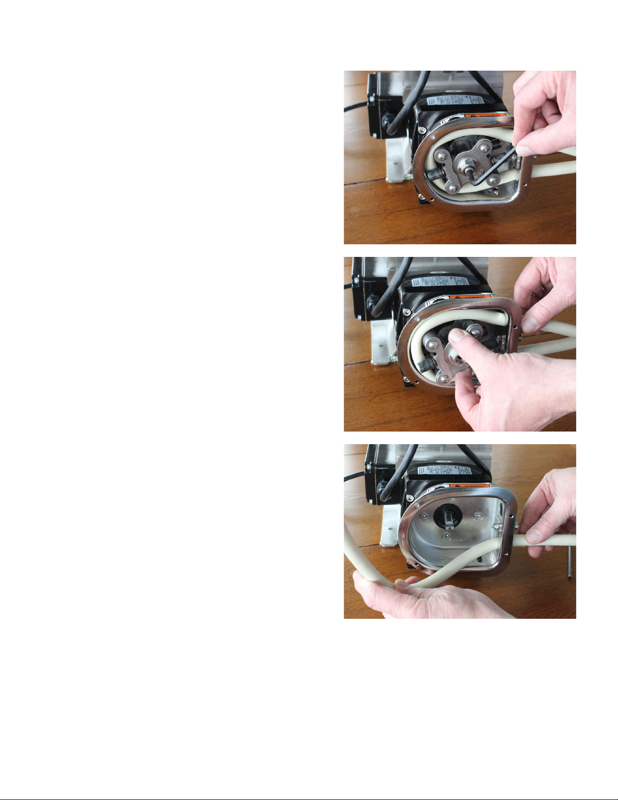
Reassembly:
1 Reinstall the collet onto the pump shaft
There is a slot in the collet that the flat drive tang on the
gearbox shaft must slide into Orient the collet to allow the
drive tang to slide into the slot and push the collet completely
onto the gearbox shaft When the collet bottoms out it is in the
correct position
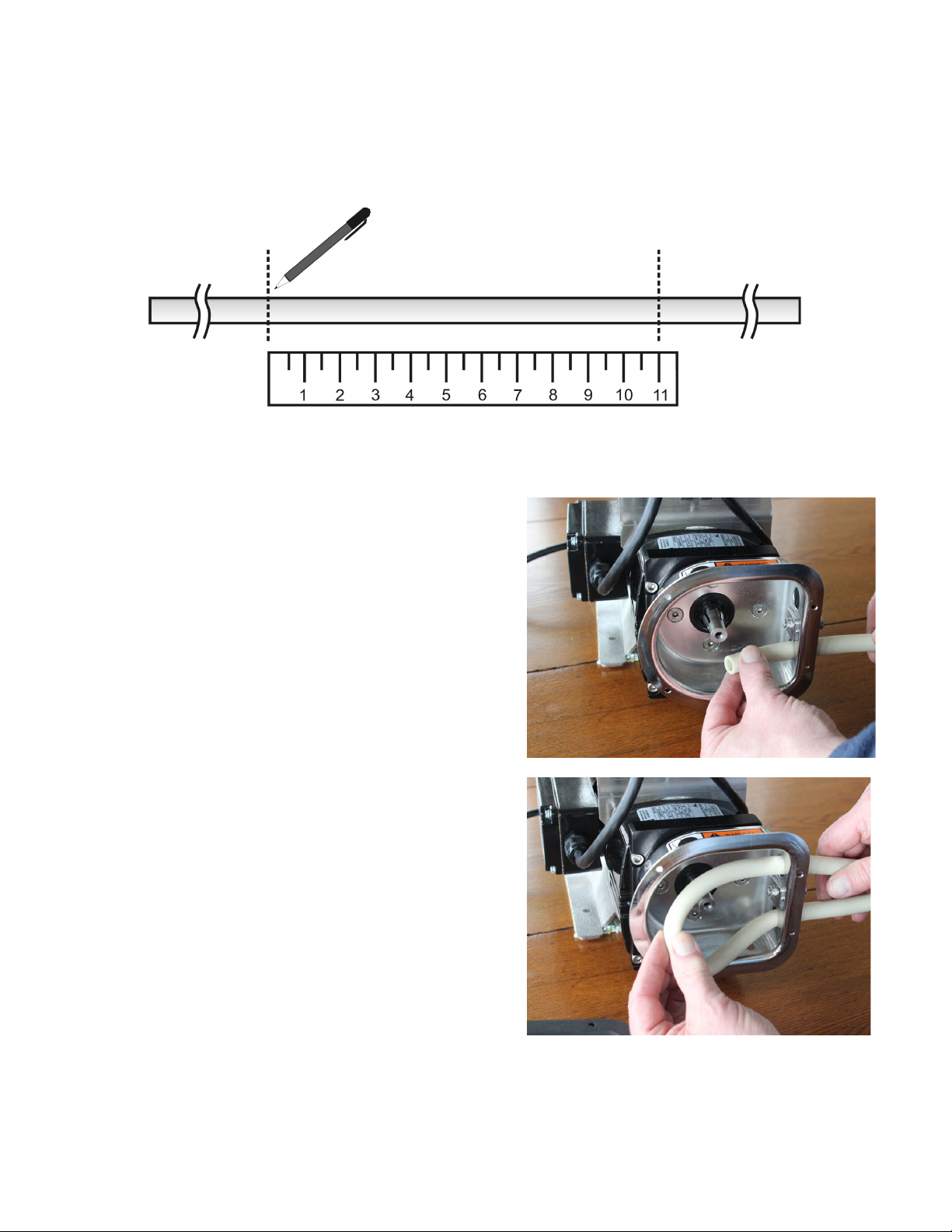
2 Mark an 11” section of hose, which will be the portion, contained within the pump Leave sufficient
excess on the suction and discharge sides of the pump for the desired connections If you leave the
excess intake tubing in a coil near the pump it will make it easy to feed a new section of tubing through
the rollers when the section in the pump becomes worn
3 Install tubing into the pumphead
Note: During hose installation the loop of tubing may
develop a twist Examine the hose for this condition and
if needed turn one end of the hose where it exits the
tubing clamp to eliminate the twist Correctly adjusted
the tubing loop will be flat and parallel to the front face
of the pump housing
Mark an 11”
section of pump hose
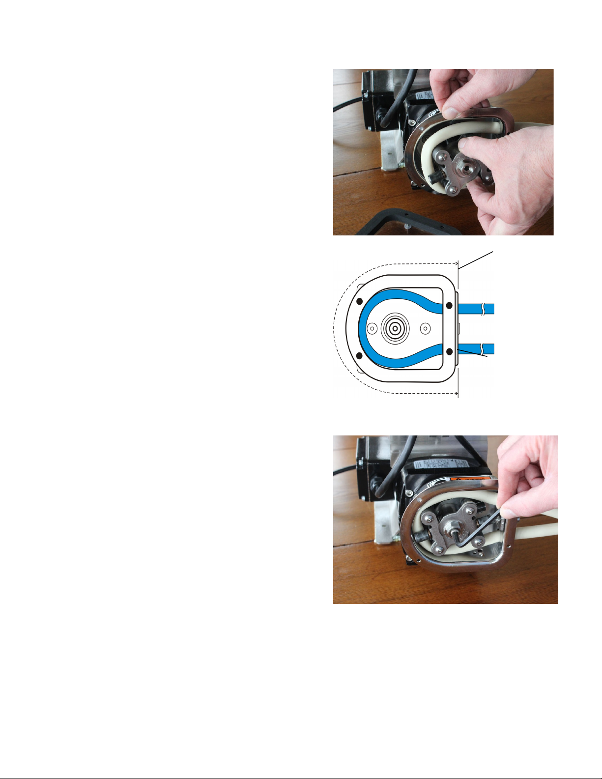
4 Loop tubing around roller assembly between guides as
shown Remove slack in tubing while rotating roller
assembly and sliding onto collet
5 Align marks on tubing with outside edge of the tubing
clamp
6 Reinstall collet screw firmly
Tubing seal size
varies with the
selected tubing size
See tables on
following pages for
details
Mark an 11 inch
length of tubing
and locate the
marks at the
outside edge of
the tubing seal
(see arrows)

7 Tighten tube seal clamp screw Be sure to tighten firmly
to prevent “tubing walk ” Tubing walk can occur when
the tube seal is the wrong size or is not sufficiently tight
to keep the rollers from pulling the tubing through the
pump as it rotates
8 Inspect pump cover gasket Replace if damaged
Reinstall pump cover gasket and cover
Align the tubing marks
with the outside edge
of the Hose Seal
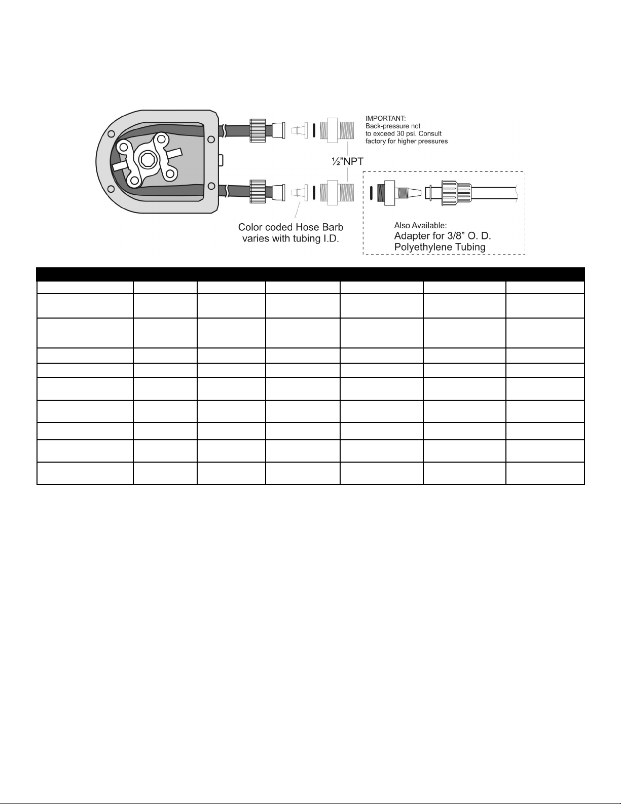
2.5 Tubing & Connections
Tubing adapters are available for many configurations See the drawing below for details
2001V SERIES ESTIMATED PUMPING CAPACITY* *Actual flow rates may vary
Tubing No. #119 #120 #15 #24 #35 #36
Tubing Size 1.6mm bore
(1/16”) 3.2mm bore
(1/8”) 4.8mm bore
(3/16”) 6.4mm bore
(1/4”) 8mm bore
(5/16”) 9.6mm bore
(3/8”)
GPH @ 1.6 - 300 rpm 0.01 - 2.1
(0.7 - 135 ml/m) 0.05 - 9.5
(3.2 - 600 ml/m) 0.1 - 14.9
(6.4 - 1200 ml/m) 0.2 - 38.0
(12.8 - 2400 ml/m) 0.2 - 53.7
(18.0 - 3390 ml/m) 0.3 - 70.3
(23.6 - 4440 ml/m)
Max Pressure (psi) 100 100 80 60 30 30
l/rev 0.45 2 4 8 11.3 14.8
Hose Barb - PVC
Color / PN
Black
HBCS2416P Gray
HBCS2432P White
HBCS2448P Black
HBCS2464P Gray
HBCS2480P White
HBCS96P
Hose Barb - PTFE
Color / PN
White
HBCS2416T White
HBCS2432T White
HBCS2448T White
HBCS2464T White
HBCS2480T White
HBCS96T
Tube Seal PN 100329 100330 100331 100332 100333 100334
Pu p Tubing
FLOPRENE FLO.016.024 FLO.032.024 FLO.048.024 FLO.064.024 FLO.080.024 FLO.096.024
Pu p Tubing
VITON VIT.016.024 VIT.032.024 VIT.048.024 VIT.064.024 VIT.080.024 VIT.096.024

3 0 – 2001V Series Gearbox
3.1 Run-in Period
The maximum efficiency of worm reducers is obtained after a “Run-In” period The length of time required will
depend on the load applied and may be two to four hours at rated load and will be considerably longer at
lighter loads During Run-In a slightly higher than normal current and temperatures along with lower efficiency
and output torque can be expected The gear box is sealed and does not require additional lubrication
3.2 2001V Series Motor Wiring
Motor Type: Permanent Split Capacitor or 3-Phase Inverter Duty
Rotation: Reversible
Insulation: Class B minimum
Finish: Powder-coat gloss black
To reverse rotation, interchange any two line leads

4 0 – K4 Pump Controller
4.1 O eration and Wiring
For complete details about the motor drive controller please refer to the included K4 SERIES Operating
Instructions booklet
IMPORTANT: Make sure the Mains voltage jum er is in the correct location for the su lied
voltage. See the K4 drive o erating instructions booklet for details.
Shown here are program settings specific to the operation with the 2001H Peristaltic Pump
4.2 Programming
The programming differs from the factory defaults shown in the SM Vector Operating Instruction booklet only in
relation to the following parameters:
KB Default Program Settings
0 04 = 0000 GFCI disabled, enable if power pump through GFCI mains circuit (some additional noise from the drive is
normal)
1 00 = 0001 Remote Start/Stop contacts enable (CHANGE TO 0000 to use 4-20 with manual start/stop)
1 05 = 0003 Power fail auto restart
2 00 = 0003 Freq Control Analog 2 (4-20mA)
2 01 = 0001 Speed change w/o pressing enter
2 02 = 0002 Enable external Local/Remote switching
3 00 = 0005 Stored Set Frequency (5hz)
3 02 = 0100 Upper Frequency Limit
4 00 = 0000 Display in user defined units (Hz)
5 00 = 0000 Enable Run Relay N O
7 03 = 0010 Remote Start/Stop - N O Start
7 04 = 0000 External Local/Remote Select OFF (13 for remote auto select)
7 06 = 0008 External Fault input select
8 00 = 0001 NC Fault Relay
8 01 = 0009 Enable Status Output
9 07 = 0020 4-20mA Input
8 09* = 0002 When speed feedback 4-20ma output is connected
NOTES:
*8 09 = 0000 to avoid fault when 4-20mA Output is disconnected when not using 4-20mA output
Keypad speed can only be changed in local mode
For manual speed with remote start/stop set 2 00 to 0000
For remote (4-20ma) speed with manual (keypad) start/stop set 1 00 to 0000
Large hose pumps - Boost Value 3 11 default 7, up to 12 or higher
6 05 = 1010 reset to Flomotion Defaults
4.3 To dis lay s eed in GPH:
Fill a calibration cylinder (best to use water, not chemical for testing and calibration)
Run the pump at full speed and time the drawdown for 30 sec (from zero level in cylinder)
Note the level in the calibration cylinder when 30 seconds has elapsed That will be your full scale pumped flow
rate
Set menu 4 00 to 0001 (custom units)
Set menu 4 01 to the GPH of the pump at full speed

4.4 Setting the maximum um ing rate
1. Fill a calibration cylinder (best to use water, not chemical for testing and calibration)
2. Run the pump at full speed and time the drawdown for 30 sec (from the zero level in the cylinder)
3. Note the level in the calibration cylinder when 30 seconds elapses That will be your full scale pumped flow rate
4. Divide the full scale pumped flow volume by the maximum hertz setting for your pump* to get volume for 1HZ
EXAMPLE:
1 Assuming the full speed drawdown test above shows 50GPH and your maximum pump frequency is 80HZ*
2 Then divide 50 / 80 = 0 625 GPH per 1 Hz
3 If your desired maximum pumping rate is to be 35GPH then divide 35 / 0 625 = 56HZ
4 Change Menu 3 02 to 56
5 Now a 20mA speed control input to the pump will equal 35GPH pumping rate
*Upper Frequency Limit; Menu 3 02

4.5 Controller Wiring Exam les

5 0 - 2001 Series Tubing Rupture Detector
Ru ture Detector System Overview
5.1 Alarm Causes
A rupture alarm is triggered by the presence of a conductive fluid in the pump When the fluid bridges the two
stainless steel electrodes in the LIQUID SENSOR in the pump the alarm is triggered
5.2 What to do in an alarm condition
To clear the alarm, first stop the pump and disconnect power from the pump controller Remove the pump
cover and remove the ruptured pump tubing Clean the inside of the pump with a soft rag Remove any liquid
or tubing debris from the inside of the pump and the area around the LIQUID SENSOR Inspect rollers and
clean if necessary
5.3 Resuming Service
Install a fresh tubing insert and the pump is ready to resume service
5.4 Resetting the alarm
Press the pushbutton (Red LED leak indicator and reset switch) on the front of the Tubing Rupture Detector to
reset the alarm
! IMPORTANT: Resetting the Tubing Ru ture Detector will cause the um to resume turning !
! ALWAYS reinstall the um cover BEFORE resetting the tubing ru ture detector !
Table of contents
Popular Water Pump manuals by other brands

IWAKI PUMPS
IWAKI PUMPS APN-110-D4 instruction manual

ALPHA WORKS
ALPHA WORKS HPT50 Operator's manual

Grundfos
Grundfos MAGNA1 D Installation and operating instructions

GORMAN-RUPP
GORMAN-RUPP SFS4C Installation, operation, and maintenance manual with parts list

Champion Power Equipment
Champion Power Equipment 66520 owner's manual

Simer
Simer BW85 Series owner's manual

Edwards
Edwards HV30000 instruction manual

Graco
Graco Lube Pro 24Z020 instructions

Ingersoll-Rand
Ingersoll-Rand ARO PD20E Series Operator's manual

Wacker Neuson
Wacker Neuson PS2A 800 Operator's manual

BEKA
BEKA Stream E 2520 Series Original operating and assembly manual

World Chemical
World Chemical SUBMERSE YD-GWN Series instruction manual


