FLS FlowX3 series User manual

ULF Ultra Low Flow Sensor
1
ULF Ultra Low Flow Sensor
INSTRUCTION MANUAL
EN 10-11
Table of Contents
1. Introduction………………………………………………………………… 2
1.1. Safety Instructions……………………………………………………………… 2
1.2. Unpacking………………………………………………………………………… 2
2. Description…………………………………………………………………. 3
2.1. Design…………………………………………………………………………….. 3
2.2. Technical Features……………………………………………………………… 3
2.3. Operating Principle……………………………………………………………... 3
2.4. Connection to FlowX3 Instruments………………………………………….. 3
2.5. Output Devices…………………………………………………………………... 4
2.5.1. K315U – Frequency Output and MIN Alarm KIT………………………….….. 4
2.5.2. K330U – 4…20mA Output KIT………………………………………………..… 4
2.5.3. Installation………………………………………………………………………… 4
3. Specifications……………………………………………………………… 5
3.1. Technical Data…………………………………………………………………… 5
3.2. Dimensions………………………………………………………………………. 8
4. Installation………………………………………………………………….. 8
4.1. Location………………………………………………………………………….. 8
4.2. Wiring…………………………………………………………………………….. 8
5. Ordering Data……………………………………………………………… 10
ULF Ultra Low Flow Sensor
2
1. Introduction
1.1. Safety Instructions
General Statements
The sensors ULF01.X.X and ULF03.X.X have only been designed to measure
the flow of liquids.
Do not install and service the sensors without following the Instruction Manual.
These sensors are designed to be connected to other instruments which can be
hazardous if used improperly. Read and follow all associated instrument
manuals before using with this sensor.
Sensor installation and wiring connections should only be performed by qualified
staff.
Do not modify product construction.
Installation and Commissioning Statements
Remove power to the sensor before wiring any connection.
Depressurize and vent the system before installing or removing the sensor.
Check and confirm the chemical compatibility of the materials in contact with the
liquid.
Do not exceed maximum temperature/pressure data.
To clean the sensor, use only chemical compatible products.
1.2. Unpacking
Please verify that the product is complete and without any damage. The following
items must be included:
ULF Ultra Low Flow Sensor
Instruction Manual for ULF Ultra Low Flow Sensor
Instruction Manual for K330U or K315U Output KIT (only for ULF3.30 or
ULF3.15 version)

ULF Ultra Low Flow Sensor
3
2. Description
2.1. Design
The compact ultra-low flow sensor type ULF is designed for use with every kind of
aggressive and solid-free liquids. The sensor can be fixed to flexible or rigid pipes via
¼” GAS threaded process connections. The paddlewheel sensor produces a frequency
output proportional to the flow velocity that can be easily transmitted and processed.
The ULF sensor offers two different flow ranges starting from 1.5 or 6 l/h (0.0066 or
0.0264 gpm). The construction materials, POM or ECTFE (Halar), provide high
strength and chemical resistance.
2.2. Technical Features
Halaris a registered trademark of Ausimont-Solvay.
2.3. Operating Principle
The flow sensor consists of a transducer and a five-blade paddlewheel. The
paddlewheel is equipped with a permanent magnet integrated into each blade. As the
magnet passes close to the transducer a pulse is generated. When liquid flows into the
sensor body, the paddlewheel is set in rotation producing a square wave output signal.
The frequency is proportional to the flow velocity.
2.4. Connections to FlowX3 Instruments
FlowX3 Instruments
FlowX3
Sensors F9.00 F9.01 F9.02 F9.03 F9.20 F9.50 F9.51
ULF01.H X X X X X
ULF01.R X X
ULF03.H X X X X X
ULF03.R X X
ULF3.15* X X X X X
ULF3.30*
*with Output KIT mounted
ULF Ultra Low Flow Sensor
4
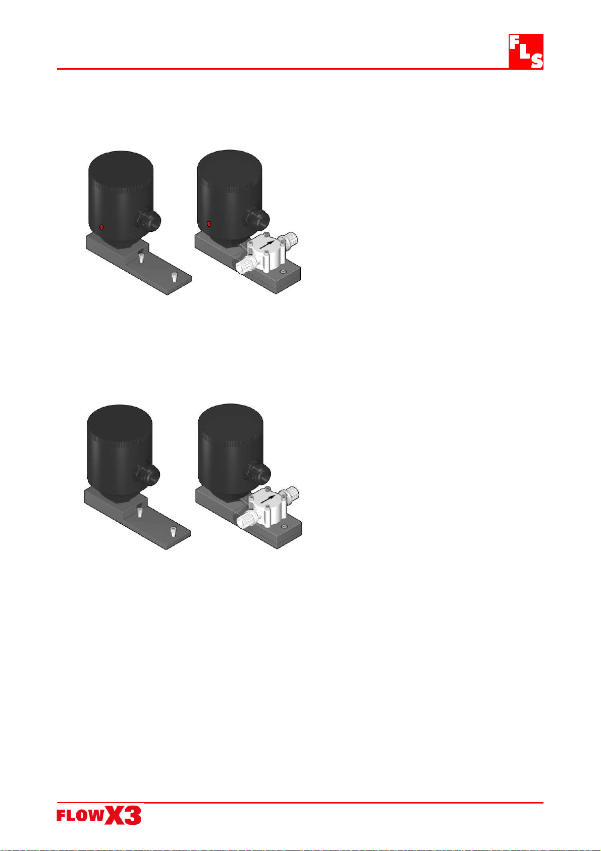
2.5. Output Devices
2.5.1. K315U – Frequency Output & MIN alarm KIT
This Kit consists of an additional IP65
housing mounted aside the sensor via a
PVC plate. It is equipped with an open
collector frequency output and a
mechanical SPDT contact. The MIN alarm
set-point can be freely set by a
potentiometer up to 21 l/h (0.09 gpm) for
ULF01 and 53 l/h (0.23 gpm) for ULF03.
When the flow velocity drops below the
adjusted limit the relay output opens and
the Local Status Indicator changes colour.
It has been designed to protect a pump
from running dry or pumping against a
closed valve in the main pipeline.
2.5.2. K330U – 4…20 mA Output KIT
This Kit consists of an additional IP65
housing mounted aside the sensor via a
PVC plate. It is a blind transmitter
designed to convert the signal from the
sensor into a 4…20 mA output for long
distance transmission.
2.5.3. Installation
The K315U and K330U Kits can be ordered directly mounted on top of the flow sensor
or separately and then simply installed on the proper sensor.
Please refer to the Instruction Manual of the Output KIT for proper installation and
calibration.

ULF Ultra Low Flow Sensor
5
3. Specifications
3.1. Technical Data
General (Hall and Reed)
Flow Rate Range:
- ULF01 version: 1.5 to 100 l/h (0.0066 to 0.44 gpm)
- ULF03 version: 6 to 250 l/h (0.0264 to 1.1 gpm)
Linearity: 1 % of full scale
Repeatability: 0.5 % of full scale
Working Temperature: -10° to 80°C (14° to 176°F)
Working Pressure: 5 bar (70 psi) max. @ 22°C (72°F)
Viscosity of fluid: 1 to 10 cST
Enclosure:IP65
Wetted Materials:
POM version:
Sensor Body: POM
O-ring: FPM
Rotor: POM
Shaft: core point
Magnets: ceramic
ECTFE version:
Sensor Body: ECTFE (Halar)
O-ring: FPM or KALREZ
Rotor: ECTFE (Halar)
Shaft: sapphire
Bearings: sapphire
Connections: ¼” GAS male
Cable length: 2 m (6.5 ft) standard
Standards & Approvals
Manufactured under ISO 9002
CE

ULF Ultra Low Flow Sensor
6
Specific for ULF01.H / ULF03.H (Hall version)
Supply voltage: 5 to 24 VDC regulated
Supply current: < 15 mA @ 24 VDC
Output signal: square wave
Calibration Data:
- ULF01 version: K-factor = 8431 Pulses/Liter (31569 Pulses/U.S. Gallon)
- ULF03 version: K-factor = 3394 Pulses/Liter (12846 Pulses/U.S. Gallon)
ULF Ultra Low Flow Sensor
7
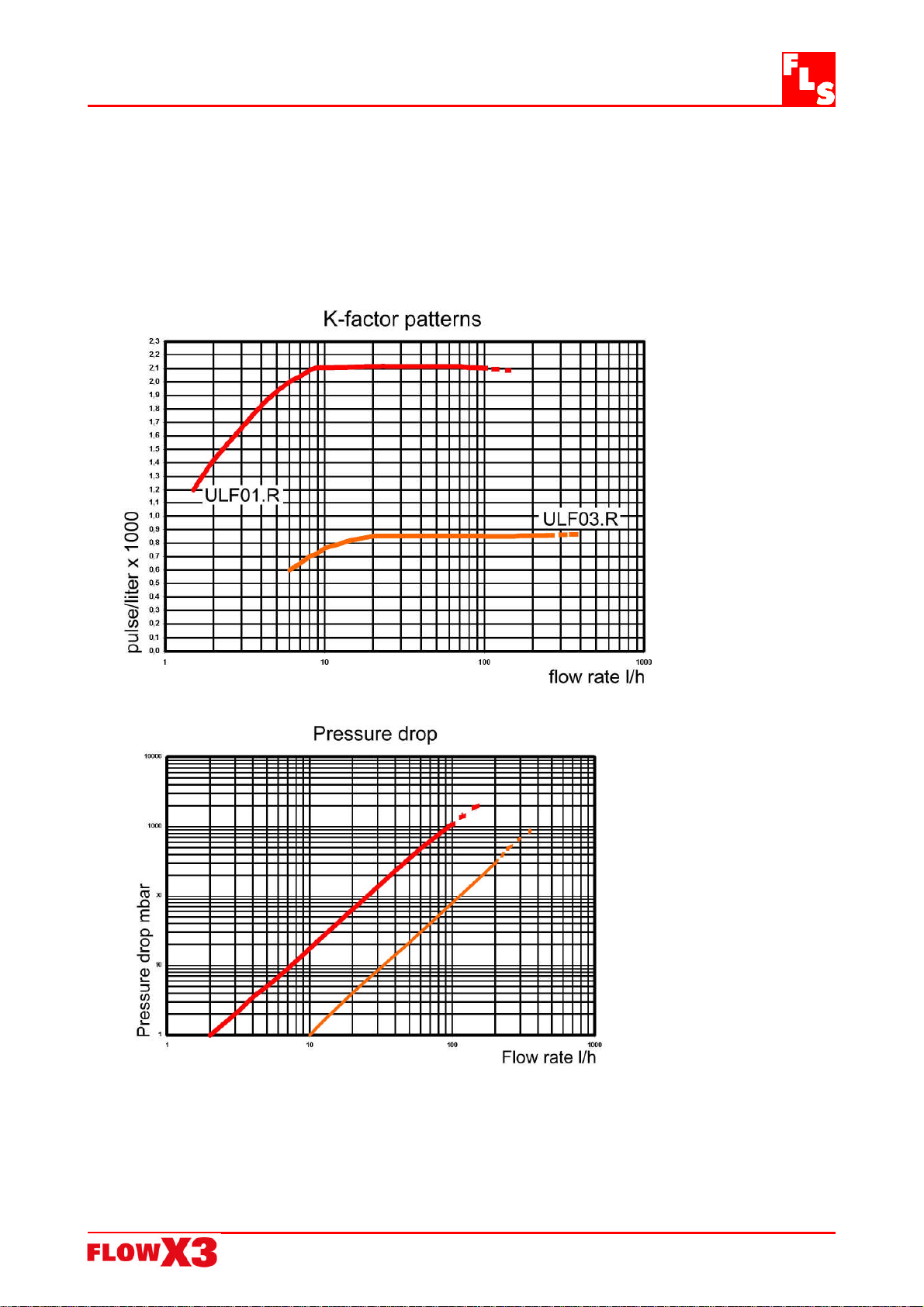
Specific for ULF01.R / ULF03.R (Reed version)
Supply voltage: none
Output signal: square wave
Output type: Reed Contact
Calibration Data:
- ULF01 version: K-factor = 2108 Pulses/Liter (7978 Pulses/U.S. Gallon)
- ULF03 version: K-factor = 848 Pulses/Liter (3210 Pulses/U.S. Gallon)

ULF Ultra Low Flow Sensor
8
3.2. Dimensions
4. Installation
4.1. Location
The sensor can be installed in any position, both horizontally or vertically, although
horizontal flow is preferred. A non horizontal installation may cause a greater error in
the lower part of the measurement range.
Install the sensor with the arrow pointing the direction of the flow.
Always maximize distance between sensor and pump. Do not install the sensor
immediately downstream of valves, elbows or any kind of obstacles: 150 mm of
straight pipe are suggested before and after the sensor.
4.2. Wiring
Always ensure the power supply is switched off before working on the sensor.
Always use a high quality (regulated) DC voltage supply.
ULFXX.H Sensor Connection to FlowX3 Instruments
Brown
Gree
n
White

ULF Ultra Low Flow Sensor
9
ULFXX.H Sensor Connection to Other Brand Instruments
ULFXX.R Sensor Connection to FlowX3 Instruments
The capacitor C and the resistor R are already included if the sensor is bought together
with the FlowX3 Battery Powered Monitor F9.20.XX and the F9.00.XX .
ULFXX.R Sensor Connection to Other Brand Instruments
Brown
Gree
n
White
Brown
Green
White
Brown
White
Green

ULF Ultra Low Flow Sensor
10
5. Ordering Data
FlowX3 ULF01.X.X
Part No. Version Power
supply Material Flow Rate Range
ULF01.H.0 Hall 5 - 24 VDC POM / FPM 1.5 to 100 l/h (0.0066 to 0.44 gpm)
ULF01.H.2 Hall 5 - 24 VDC ECTFE / FPM 1.5 to 100 l/h (0.0066 to 0.44 gpm)
ULF01.H.3 Hall 5 - 24 VDC ECTFE / KALREZ 1.5 to 100 l/h (0.0066 to 0.44 gpm)
ULF01.R.0 Reed None POM / FPM 1.5 to 100 l/h (0.0066 to 0.44 gpm)
ULF01.R.2 Reed None ECTFE / FPM 1.5 to 100 l/h (0.0066 to 0.44 gpm)
ULF01.R.3 Reed None ECTFE / KALREZ 1.5 to 100 l/h (0.0066 to 0.44 gpm)
FlowX3 ULF03.X.X
Part No. Version Power
supply Material Flow Rate Range
ULF03.H.0 Hall 5 - 24 VDC POM / FPM 6 to 250 l/h (0.0264 to 1.1 gpm)
ULF03.H.2 Hall 5 - 24 VDC ECTFE / FPM 6 to 250 l/h (0.0264 to 1.1 gpm)
ULF03.H.3 Hall 5 - 24 VDC ECTFE / KALREZ 6 to 250 l/h (0.0264 to 1.1 gpm)
ULF03.R.0 Reed None POM / FPM 6 to 250 l/h (0.0264 to 1.1 gpm)
ULF03.R.2 Reed None ECTFE / FPM 6 to 250 l/h (0.0264 to 1.1 gpm)
ULF03.R.3 Reed None ECTFE / KALREZ 6 to 250 l/h (0.0264 to 1.1 gpm)
FlowX3 ULF3.15.XX.X (with O.C. output & MIN alarm)
Part No. Version Power
supply Material Flow Rate Range
ULF3.15.01.0 Hall 12 - 24 VDC POM / FPM 1.5 to 100 l/h (0.0066 to 0.44 gpm)
ULF3.15.01.2 Hall 12 - 24 VDC ECTFE / FPM 1.5 to 100 l/h (0.0066 to 0.44 gpm)
ULF3.15.01.3 Hall 12 - 24 VDC ECTFE / KALREZ 1.5 to 100 l/h (0.0066 to 0.44 gpm)
ULF3.15.03.0 Hall 12 - 24 VDC POM / FPM 6 to 250 l/h (0.0264 to 1.1 gpm)
ULF3.15.03.2 Hall 12 - 24 VDC ECTFE / FPM 6 to 250 l/h (0.0264 to 1.1 gpm)
ULF3.15.03.3 Hall 12 - 24 VDC ECTFE / KALREZ 6 to 250 l/h (0.0264 to 1.1 gpm)
FlowX3 ULF3.30.XX.X (with 4…20 mA output)
Part No. Version Power
supply Material Flow Rate Range
ULF3.30.01.0 Hall 12 - 24 VDC POM / FPM 1.5 to 100 l/h (0.0066 to 0.44 gpm)
ULF3.30.01.2 Hall 12 - 24 VDC ECTFE / FPM 1.5 to 100 l/h (0.0066 to 0.44 gpm)
ULF3.30.01.3 Hall 12 - 24 VDC ECTFE / KALREZ 1.5 to 100 l/h (0.0066 to 0.44 gpm)
ULF3.30.03.0 Hall 12 - 24 VDC POM / FPM 6 to 250 l/h (0.0264 to 1.1 gpm)
ULF3.30.03.2 Hall 12 - 24 VDC ECTFE / FPM 6 to 250 l/h (0.0264 to 1.1 gpm)
ULF3.30.03.3 Hall 12 - 24 VDC ECTFE / KALREZ 6 to 250 l/h (0.0264 to 1.1 gpm)

ULF Ultra Low Flow Sensor
11
Output Devices
Part No. Housing Gaskets Enclosure Description
ULF.K315U PVC EPDM IP65 Frequency Output & MIN Alarm KIT
ULF.K330U PVC EPDM IP65 4-20 mA Output KIT
Spare Parts
Item Part No. Name Description
1ULF.SP1U PVC Plate PVC Adapter for K315U or K330U Kit
F3.SP6 Electrical cable Cable (per meter), 3cond., 22AWG
2F3.SP7 PG11 PG11 Cable Gland for K315 or K330 Kit

ULF Ultra Low Flow Sensor
12
F.I.P.
Formatura Iniezione Polimeri S.p.A.
Loc. Pian di Parata, 16015 Casella (GE) – Italy
Tel +39 010 96211 – Fax +39 010 9621209
www.flsnet.it
Other manuals for FlowX3 series
1
This manual suits for next models
2
Table of contents
Other FLS Accessories manuals


Popular Accessories manuals by other brands


DANA
DANA 2000-10 parts list

S+S Regeltechnik
S+S Regeltechnik KYMASGARD AFTF-HK-FSE Operating Instructions, Mounting & Installation

Burster
Burster 8625 Operation manual

Furuno
Furuno FI-3002 Operator's manual

Teledyne
Teledyne TIENet 350 Installation and operation guide

Air Naturel
Air Naturel Airom user manual