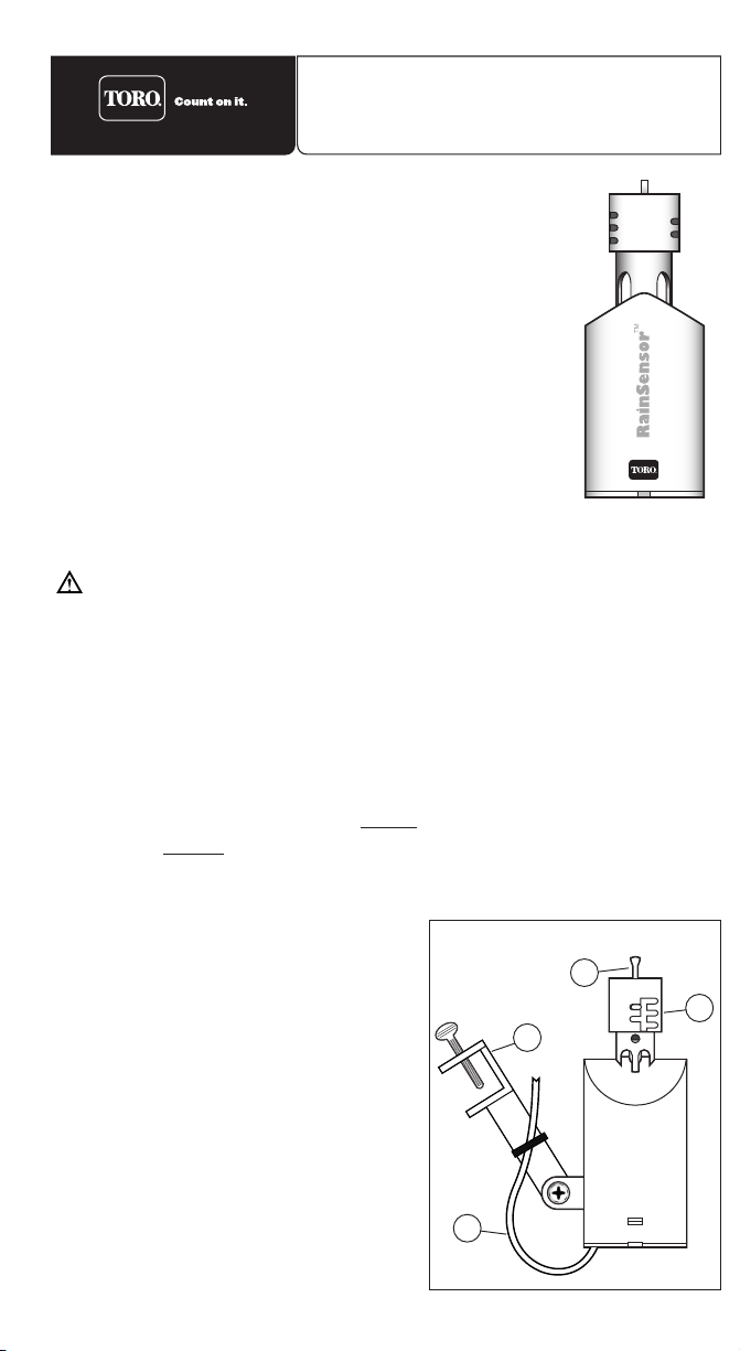
Connecting the RainSensor Control Wire
Caution: Do not attach the RainSensor control wire direct-
ly to 120/240 V ac power as this may result in irreversible
damage. If you are in doubt, contact a qualified installer or
electrician.
1. Disconnect power to the controller.
2. Follow the applicable instructions provided in steps A or B or C.
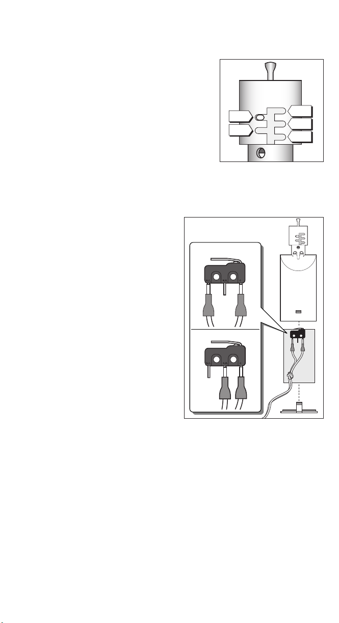
Find the controller sensor terminals (generally marked “SENSOR”,
“SEN”or “S”) and attach the RainSensor control wires directly to
these terminals in any order.
Note: There may be a jumper tab or wire between the sensor termi-
nals that must be removed and/or a sensor control or bypass switch
that must be activated.
Remove the valve common wire(s) from the valve common terminal
and join to either RainSensor control wire using the supplied wire
connector. Attach the remaining RainSensor control wire to the
valve common terminal.
Disconnect all common wires from the common terminal(s) and join
them to either RainSensor control wire using the supplied wire
connector. Be sure to include the common wire from the pump start
relay or master valve in this connection. Connect the remaining
RainSensor control wire to the valve common terminal.
Operation
Testing the Installation
To test the RainSensor operation, turn on a watering zone which is
visible from the RainSensor location.
Note: The manual activation cycle of some controllers bypasses
the sensor inputs. If the RainSensor is connected to the sensor ter-
minals, you will need to run an automatic/timed watering program
for these types of controllers.
With the sprinklers on, manually activate the RainSensor by press-
ing and holding the Test Spindle at the top of the unit. The sprin-
klers should shut off within a short time. If they do not shut off,
recheck the wiring connections at the controller. If the controller has
a sensor control or bypass switch, make sure the switch is set to
the position that will enable the sensor circuit to be active.
Normal Operation
When the RainSensor activates due to sufficient rainfall, the sprin-
kler system will become inactive until the moisture-absorbent discs
inside the RainSensor have dried out. The rate at which the discs
dry out will vary dependent on temperature, sun exposure, humidity
and wind—the same conditions your soil experiences. This allows
the RainSensor to reset when watering is needed again, enabling
the sprinkler system to resume normal operation.
Bypassing the RainSensor
The RainSensor can be temporarily bypassed or deactivated using
any one of the following methods:
•Use the controller’s sensor bypass switch (if equipped).
•Install an optional bypass switch.
•Temporarily disconnect the RainSensor from the controller’s wiring.
Note: Always disconnect power to the controller before performing
any wiring tasks.
Specifications
Mounting: Quick-ClipTM rain gutter bracket or screws (2 provided)
Control Wire: 25' outdoor-rated, 2-wire cable, UL approved
Sensor Type: Industry-standard hygroscopic disc stack with
adjustable rainfall sensitivity
Rating: 3 amp, 24 V ac, NO/NC
Operating Temperature Range: -20°F to 140°F
Hardware: Stainless steel
Housing: UV-resistant engineered polymer
The Toro Promise —Limited One-Year Warranty
The Toro Company and its affiliate, Toro Warranty Company, pursuant to an agreement
between them, jointly warrants, to the owner against defects in material and workmanship for
a period of one year from the date of purchase.
Neither The Toro Company nor Toro Warranty Company is liable for failure of products not
manufactured by them even though such products may be sold or used in conjunction with
Toro products.
During such warranty period, we will repair or replace, at our option, any part found to be
defective.
Return the defective part to the place of purchase.
Our liability is limited solely to the replacement or repair of defective parts. There are no other
express warranties.
This warranty does not apply where equipment is used, or installation is performed, in any
manner contrary to Toro’s specifications and instructions, nor where equipment is altered or
modified.
NEITHER THE TORO COMPANY NOR TORO WARRANTY COMPANY IS LIABLE FOR
INDIRECT, INCIDENTAL OR CONSEQUENTIAL DAMAGES IN CONNECTION WITH THE
USE OF EQUIPMENT, INCLUDING BUT NOT LIMITED TO: VEGETATION LOSS, THE
COST OF SUBSTITUTE EQUIPMENT OR SERVICES REQUIRED DURING PERIODS OF
MALFUNCTION OR RESULTING NON-USE, PROPERTY DAMAGE OR PERSONAL
INJURY RESULTING FROM INSTALLER’S NEGLIGENCE.
Some states do not allow the exclusion or limitation of incidental or consequential damages,
so the above limitation or exclusion may not apply to you.
ALL IMPLIED WARRANTIES, INCLUDING THOSE OF MERCHANTABILITY AND FITNESS
FOR USE, ARE LIMITED TO THE DURATION OF THIS EXPRESS WARRANTY.
Some states do not allow limitations of how long an implied warranty lasts, so the above limi-
tation may not apply to you.
This warranty gives you specific legal rights and you may have other rights which vary from
state to state.
COM
PUMP/
MV 24 VAC
21 34
Common Wire From Valves
To Valves
Wire Connector
Irrigation System Controller
SENSOR
COM
PUMP/
MV 24 VAC
21 34
Irrigation System Controller
Common Wire From Valves
To Valves
COM
PUMP/
MV 24 VAC
21 34
Common Wire From Valves
To Valves
Pump Start
Relay/Master
Valve
Irrigation System Controller
Wire Connector
© 2003 The Toro Company, Consumer Division, An ISO 9000-certified Company
P.O. Box 489, Riverside CA, 92502 •Toro Helpline - 1-800-367-8676 •www.toro.com
Form Number 102-4292 Rev. A
Controllers with sensor terminals, with or without pump
start/master valve:
Controllers with pump start/master valve and no sensor
terminal:
C
Controllers with no sensor terminals and no pump start/
master valve:
B
A