FLS K315 User manual

K315 – Frequency Output & MIN Alarm KIT
1
K315 - Frequency Output & MIN alarm KIT for
Paddlewheel Flow Sensor
INSTRUCTION MANUAL EN 10-11
Table of Contents
1. Introduction………………………………………………………………… 2
Safety Instructions………………………………………………………………. 2
Unpacking………………………………………………………………………… 2
2. Description……………………………………………………………….… 2
3. Specifications…………………………………………………………….... 3
Technical Data…………………………………………………………………… 3
Dimensions……………………………………………………..……………..…. 3
4. Installation………………………………………………………………….. 4
Sensor Assembly………………………………………………………………… 4
Wiring………………………………………………………………………………. 4
5. Calibration………………………………………………………………….. 6
Calibration Mode………………………………………………………………... 6
Operative Mode……………………………………………………………..…… 6
6. Troubleshooting………………………………………………………..…. 7
7. Ordering Data……………………………………………………………… 7
K315 – Frequency Output & MIN Alarm KIT
2
1. Introduction
1.1. Safety Instructions
General Statements
Do not install and service the device without following the Instruction Manual.
This unit is designed to be connected to other instruments which can be
hazardous if used improperly. Read and follow all associated instrument
manuals before using with this sensor.
Installation and wiring connections should only be performed by qualified staff.
Do not modify product construction.
Installation and Commissioning Statements
Remove power to the device before wiring any connection.
When the unit is powered and the cover is open, protection against electric
shocks is not ensured.
Do not exceed published specifications using this instrument.
To clean the device, use only chemical compatible products.
1.2. Unpacking
Please verify that the product is complete and without any damage. The following
items must be included:
K315 – Frequency Output & MIN Alarm KIT for Paddlewheel Flow Sensor with
black sensor cap included
Instruction Manual
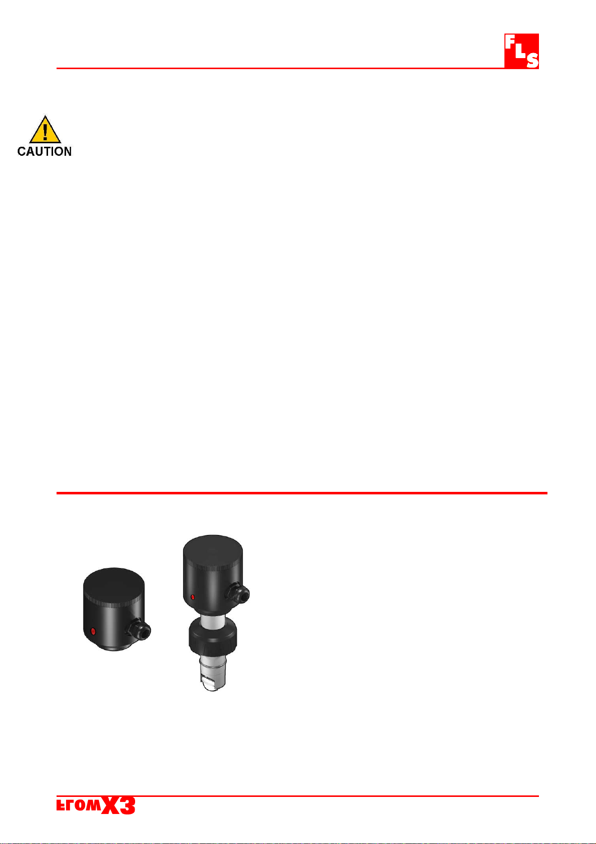
2. Description
This Kit consists of an additional IP65 housing
plugged on the sensor. It is equipped with an open
collector frequency output and a mechanical SPDT
contact. The MIN alarm set-point can be freely set
by a potentiometer from 0.15 to 1 m/s ( 0.5 to 3.3
ft/s). When the flow velocity drops below the
adjusted limit the relay output opens and the Local
Status Indicator changes colour. It has been
designed to protect a pump from running dry or
pumping against a closed valve in the main pipeline.
K315 – Frequency Output & MIN Alarm KIT
3
3. Specifications
3.1. Technical Data
Associated Flow Sensor: Hall effect (F3.01.H.XX Compact version)
Supply voltage: 12 to 24 VDC regulated
Output signal: square wave
Output frequency: 45Hz per m/s nominal (13.7 Hz per ft/s nominal)
Output type: transistor NPN open collector
Output current: 10 mA max.
Relay Output: mechanical SPDT contact, 3 A @ 30 VDC, 3 A @ 250VAC resistive load
Flow trip point: 0.15 to 1 m/s (0.5 to 3 ft/s) freely adjustable
Local Status Indicator: GREEN Led = Flow RED Led = No Flow
Enclosure: IP65
Operating temperature: 0 to 60°C (32 to 140°F)
Relative humidity: 0 to 95% non-condensing
Housing material: PVC
Standards & Approvals
Manufactured under ISO 9002
CE
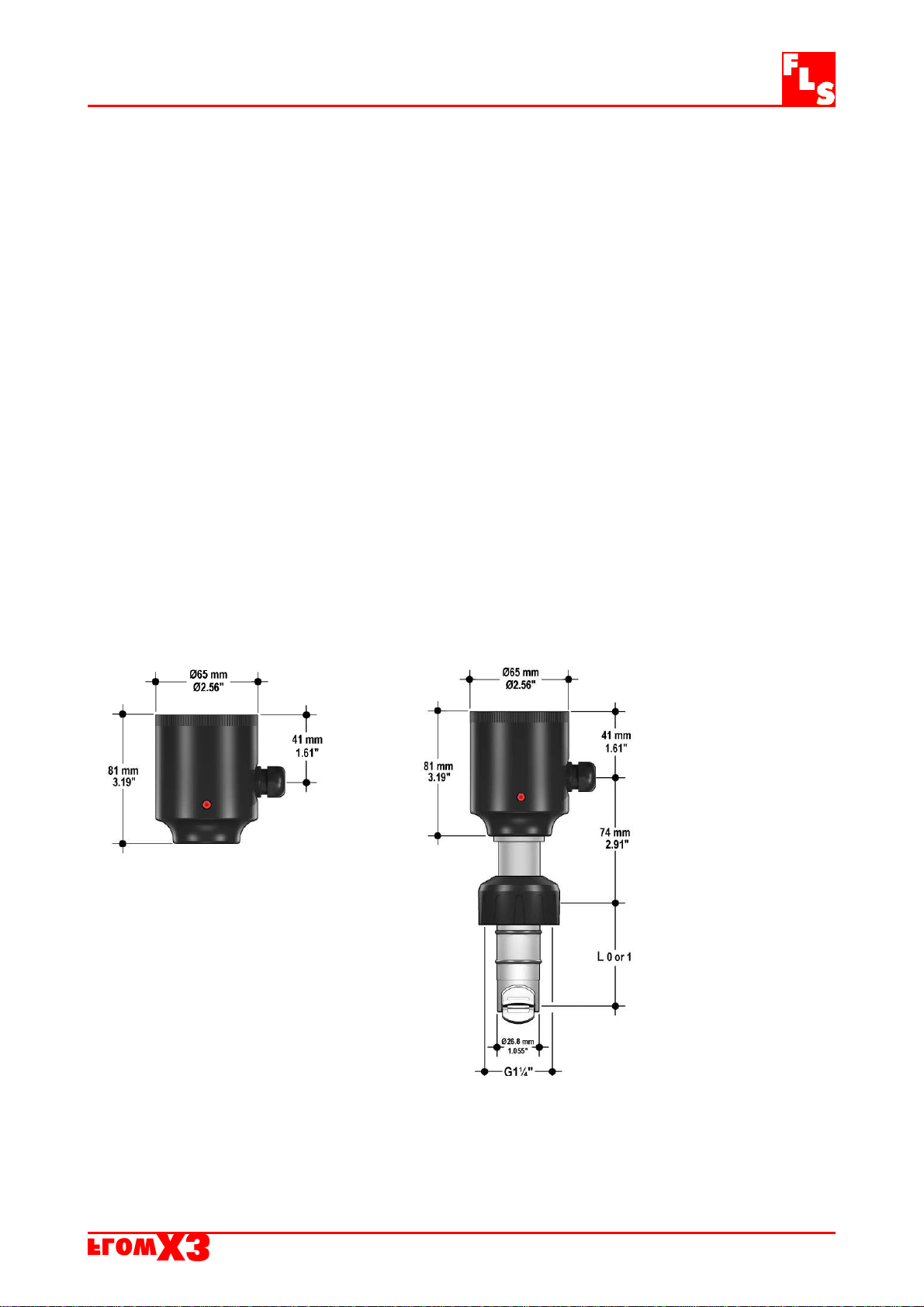
3.2. Dimensions
K315 KIT F3.15 Sensor with O.C. output & MIN alarm
L0 = 68.3 mm (2.69 in)
L1 = 98.5 mm (3.88 in)
K315 – Frequency Output & MIN Alarm KIT
4
4. Installation
4.1. Sensor Assembly
Screw down completely the electronic box to have a perfect sealing between the
sensor and the box.
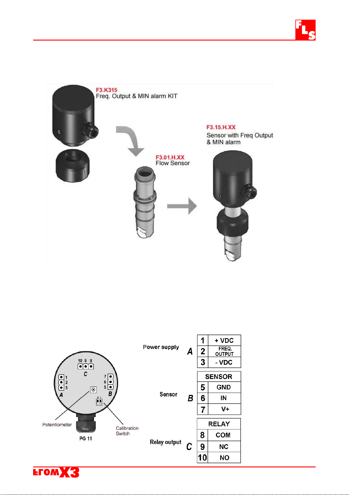
4.2. Wiring
Unscrew the top cover to reach the electrical connections. All wiring connections to
K3.15 are made via removable terminals.

K315 – Frequency Output & MIN Alarm KIT
5
General recommendation
Always ensure the power supply is switched off before working on the device.
Terminals accept 26 to 12 AWG (0.08 to 2.5 mm2)
Strip around 10 mm (0.4”) of insulation from the wire tips and tin bare ends to
avoid fraying.
Ferrules are suggested when connecting more than one wire to a single terminal.
Remove the upper part of the terminals for an easy cabling.
Insert wire tip or ferrule completely into the terminal and fix with the screw until
finger tight
Sensor Wiring Diagram Power Wiring Diagram
Relay Wiring Diagram
The alarm is OFF during
normal operation.
In alarm condition the
Local Status Indicator
(LED) is RED.
Frequency Output Wiring Diagram
Connection to FlowX3 Instruments
The FlowX3 monitor does not
provide power supply to the K315
KIT.
External power supply is required.
Table of contents
Other FLS Accessories manuals


