Safety instructions
Z6AM A01559_03_Y00_00 HBM: public 3
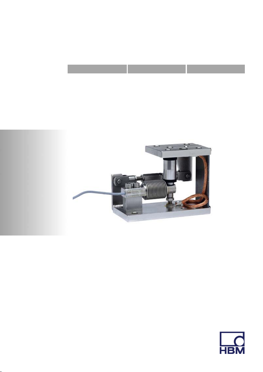
1 Safety instructions
In cases where a breakage would cause injury to persons or damage to equip
ment, the user must take appropriate safety measures (such as fall protection,
overload protection, etc.). For safe and trouble‐free operation, weighing mod
ules must not only be correctly transported, stored, sited and installed but must
also be carefully operated and maintained.
It is essential to comply with the relevant accident prevention regulations. In
particular you should take into account the limit loads quoted in the specifica
tions.
Use in accordance with the regulations
Z6AM type weighing modules are conceived for weighing applications. Use for
any additional purpose shall be deemed to be not in accordance with the
regulations.
In the interests of safety, the weighing modules should only be operated as
described in the Mounting Instructions. It is also essential to observe the
appropriate legal and safety regulations for the application concerned during
use. The same applies to the use of accessories.
The weighing modules are not safety elements within the meaning of its use as
intended. Proper and safe operation of this transducer requires proper
transportation, correct storage, assembly and mounting and careful operation
and maintenance.
General dangers due to non‐observance of the safety instructions
The Z6AM weighing modules correspond to the state of the art and are
fail‐safe. The weighing modules can give rise to residual dangers if they are
inappropriately installed and operated by untrained personnel.
Everyone involved with the installation, commissioning, maintenance or repair
of a force transducer must have read and understood the Mounting Instructions
and in particular the technical safety instructions.