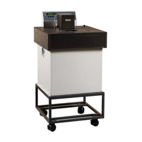
Fluke Calibration 7103 User manual

7103
Micro-Bath
User’s Guide
December 2013 Rev. 1, 3/22
© 2013-2022 Fluke Corporation. All rights reserved. Specifications are subject to change without notice.

LIMITED WARRANTY AND LIMITATION OF LIABILITY
Each Fluke product is warranted to be free from defects in material and workmanship under normal use and
service. The warranty period is one year and begins on the date of shipment. Parts, product repairs, and services
are warranted for 90 days. This warranty extends only to the original buyer or end-user customer of a Fluke
authorized reseller, and does not apply to fuses, disposable batteries, or to any product which, in Fluke's opinion,
has been misused, altered, neglected, contaminated, or damaged by accident or abnormal conditions of operation
or handling. Fluke warrants that software will operate substantially in accordance with its functional specifications
for 90 days and that it has been properly recorded on non-defective media. Fluke does not warrant that software
will be error free or operate without interruption.
Fluke authorized resellers shall extend this warranty on new and unused products to end-user customers only but
have no authority to extend a greater or different warranty on behalf of Fluke. Warranty support is available only if
product is purchased through a Fluke authorized sales outlet or Buyer has paid the applicable international price.
Fluke reserves the right to invoice Buyer for importation costs of repair/replacement parts when product purchased
in one country is submitted for repair in another country.
Fluke's warranty obligation is limited, at Fluke's option, to refund of the purchase price, free of charge repair, or
replacement of a defective product which is returned to a Fluke authorized service center within the warranty
period.
To obtain warranty service, contact your nearest Fluke authorized service center to obtain return authorization
information, then send the product to that service center, with a description of the difficulty, postage and insurance
prepaid (FOB Destination). Fluke assumes no risk for damage in transit. Following warranty repair, the product will
be returned to Buyer, transportation prepaid (FOB Destination). If Fluke determines that failure was caused by
neglect, misuse, contamination, alteration, accident, or abnormal condition of operation or handling, including
overvoltage failures caused by use outside the product's specified rating, or normal wear and tear of mechanical
components, Fluke will provide an estimate of repair costs and obtain authorization before commencing the work.
Following repair, the product will be returned to the Buyer transportation prepaid and the Buyer will be billed for the
repair and return transportation charges (FOB Shipping Point).
THIS WARRANTY IS BUYER'S SOLE AND EXCLUSIVE REMEDY AND IS IN LIEU OF ALL OTHER
WARRANTIES, EXPRESS OR IMPLIED, INCLUDING BUT NOT LIMITED TO ANY IMPLIED WARRANTY OF
MERCHANTABILITY OR FITNESS FOR A PARTICULAR PURPOSE. FLUKE SHALL NOT BE LIABLE FOR ANY
SPECIAL, INDIRECT, INCIDENTAL, OR CONSEQUENTIAL DAMAGES OR LOSSES, INCLUDING LOSS OF
DATA, ARISING FROM ANY CAUSE OR THEORY.
Since some countries or states do not allow limitation of the term of an implied warranty, or exclusion or limitation
of incidental or consequential damages, the limitations and exclusions of this warranty may not apply to every
buyer. If any provision of this Warranty is held invalid or unenforceable by a court or other decision-maker of
competent jurisdiction, such holding will not affect the validity or enforceability of any other provision.
11/99
Fluke Corporation
P.O. Box 9090
Everett, WA 98206-9090
U.S.A.
Fluke Europe B.V.
P.O. Box 1186
5602 BD Eindhoven
The Netherlands

i
Table of Contents
Title Page
Introduction................................................................................................ 1
Safety Information ..................................................................................... 2
Contact Fluke Calibration .......................................................................... 2
Service Information.................................................................................... 2
Specifications ............................................................................................ 3
Bath Environment ................................................................................. 4
Bath Fluids (Summary) ......................................................................... 4
Unpack the Product .............................................................................. 4
Setup ......................................................................................................... 5
Power.................................................................................................... 5
Set the Temperature............................................................................. 6
Thermal Electric Devices ...................................................................... 6
Bath Use ............................................................................................... 6
Calibration of Multiple Probes .......................................................... 7
Parts and Controls..................................................................................... 7
Back Panel............................................................................................ 7
Front Panel ........................................................................................... 8
Accessories .......................................................................................... 10
Transport/Pour Access Lid............................................................... 10
Access Cover................................................................................... 11
Probe Basket ................................................................................... 11
Stir Bar ............................................................................................. 12
Comparison Calibration.................................................................... 12
General Operation ..................................................................................... 13
Change Display Units ........................................................................... 13
Bath Fluid.............................................................................................. 13
Fluid Safety ...................................................................................... 13
Temperature Range......................................................................... 14
Viscosity........................................................................................... 14
Specific Heat.................................................................................... 14
Thermal Conductivity ....................................................................... 14
Thermal Expansion .......................................................................... 14
Electrical Resistivity ......................................................................... 14
Fluid Lifetime.................................................................................... 14
Cost.................................................................................................. 15

7103
User’s Guide
ii
Water (Distilled) ............................................................................... 15
Mineral Oil........................................................................................ 15
Silicone Oil (Dow Corning 200.05, 200.10, 200.20)......................... 15
Fluid Characteristics Charts.................................................................. 16
Limitations and Disclaimer ............................................................... 17
About the Graph............................................................................... 18
Stirring ....................................................................................................... 18
Fluid Drain ................................................................................................. 19
Temperature Controller ............................................................................. 19
Controller Operation .................................................................................. 19
Well Temperature...................................................................................... 20
Temperature Set-point .............................................................................. 20
Programmable Set-points..................................................................... 20
Set-point Value ..................................................................................... 22
Temperature Scale Units...................................................................... 22
Scan .......................................................................................................... 22
Scan Control......................................................................................... 22
Scan Rate............................................................................................. 22
Temperature Display Hold......................................................................... 23
Mode Setting ........................................................................................ 23
Switch Wiring........................................................................................ 23
Switch Test Example ............................................................................ 24
Secondary Menu ....................................................................................... 24
Thermal Electric Device (TED) Control ..................................................... 24
Proportional Band...................................................................................... 25
Controller Configuration ............................................................................ 26
Operating Parameters .......................................................................... 26
High Limit ......................................................................................... 26
Stir Speed ........................................................................................ 26
Serial Interface Parameters.................................................................. 27
BAUD Rate ...................................................................................... 27
Sample Period ................................................................................. 27
Duplex Mode.................................................................................... 28
Linefeed ........................................................................................... 28
Calibration Parameters......................................................................... 28
HARD Cut-out .................................................................................. 29
R0 .................................................................................................... 29
ALPHA ............................................................................................. 29
DELTA ............................................................................................. 29
BETA................................................................................................ 29
Digital Communication Interface ............................................................... 29
Serial Communications ............................................................................. 30
Wiring ................................................................................................... 30
Setup .................................................................................................... 30
Serial Operation.................................................................................... 30
Interface Commands ................................................................................. 30
Calibrate a Single Probe ........................................................................... 32
Calibration ................................................................................................. 33
Calibration Points ...................................................................................... 33
Calibration Procedure................................................................................ 34

Micro-Bath
Table of Contents
iii
Compute DELTA................................................................................... 35
Compute R0 & ALPHA ......................................................................... 36
Accuracy and Repeatability .................................................................. 37
Stabilization and Accuracy ........................................................................ 37
Maintenance .............................................................................................. 37
Troubleshooting Problems, Possible Causes, and Solutions.................... 38

7103
User’s Guide
iv

1
Introduction
The Fluke Calibration 7103 Micro-Bath (the Product, calibrator, or instrument) is a portable instrument/
bench-top temperature calibrator. Use the Product to calibrate thermocouple and RTD temperature
probes. The Product is small enough to use in the field, and accurate enough to use in the lab. With an
ambient temperature of 23 °C (74 °F), calibrate over a range of −30 °C to 125 °C (-22 °F to 257 °F).
The resolution of the display is 0.01 degrees.
The Product features:
• Convenient handle
• RS-232 interface
Built in programmable features include:
• Temperature scan rate control
• Temperature switch hold
• Eight Set-point memory
• Adjustable readout in °C or °F
The temperature is accurately controlled by a hybrid analog/digital controller. The controller uses a
precision platinum RTD as a sensor and controls the well temperature with thermal electric devices
(TED).
The LED front panel (display) continuously shows the current well temperature. Set the temperature
with the control keys to any desired temperature within the specified range. Multiple fault protection
devices ensure user and Product safety and protection.
Through proper use, the Product continuously provides accurate calibration of temperature sensors
and devices.

7103
User’s Guide
2
Safety Information
General Safety Information is in the printed Safety Information document that shipped with the Product.
It can also be found online at www.Flukecal.com.More specific safety information is listed in this
manual where applicable.
A Warning identifies conditions and procedures that are dangerous to the user. A Caution identifies
conditions and procedures that can cause damage to the Product or the device under test (DUT).
WCautions
To avoid possible damage to the Product, follow these guidelines:
• Read Bath Use before placing the bath in service. Incorrect handling can damage the
Product and void the warranty.
• Do not turn off the Product at temperatures >100 °C. This could create a hazardous
situation. Select a set-point <100 °C and allow the Product to cool before you turn it
off.
• Allow at least 150 mm (6 in) of space between the Product and nearby objects.
Contact Fluke Calibration
Fluke Corporation operates worldwide. For local contact information, go to our website:
www.flukecal.com
To register your product, view, print, or download the latest manual or manual supplement, go to our
website.
Fluke Corporation
P.O. Box 9090
Everett, WA 98206-9090
+1-425-446-5500
Service Information
Contact an authorized Fluke Calibration Service Center if the Product needs calibration or repair during
the warranty period. Please have Product information such as the purchase date and serial number
ready when you schedule a repair.

Micro-Bath
Specifications
3
Specifications
Table 1. Specifications
Range -30 °C to 125 °C (22 °F to 257 °F)
Accuracy ±0.25 °C
Stability ±0.03 °C at -25 °C (oil, 5010)
±0.05 °C at 125 °C (oil, 5010)
Uniformity ±0.02 °C
Resolution 0.01 °C/°F
Heating Time 25 °C to 100 °C (77 °F to 212 °F): 35 minutes
Cooling Time 25 °C to -25 °C (77 °F to -13 °F): 30 minutes
Well Size 64 mm x 139 mm deep (2.5 in x 5.5 in deep)
(access opening is 48 mm [1.9 in] in diameter)
Size (WxHxD) 230 mm x 340 mm x 260 mm (9 in x 13.2 in x 10.5 in)
Weight 10 kg (22 lb) with fluid
Power 115/230 VAC (±10 %), 50/60 Hz, 650 VA
Fuse Rating T 5 A 250 V
Cooling Fan and Thermal Electric Devices (TED)
Fault Protection Short protection
Ambient temperature range 5 °C to 45 °C (41 °F to 113 °F)
Ambient relative humidity Maximum 80 % RH for temperature <31 °C (88 °F), decreasing linearly to 35 % RH at 45 °C
(113 °F)
Altitudes <2000 m
Safety
General
Heating
IEC 61010-1: Overvoltage Category II, Pollution Degree 2
IEC 61010-2-010
Electromagnetic Compatibility (EMC)
International.......................IEC 61326-1: Basic Electromagnetic Environment
CISPR 11: Group 1, Class A
Group 1: Equipment has intentionally generated and/or uses conductively-coupled radio
frequency energy that is necessary for the internal function of the equipment itself. Class
A: Equipment is suitable for use in all establishments other than domestic and those
directly connected to a low-voltage power supply network that supplies buildings used for
domestic purposes. There may be potential difficulties in ensuring electromagnetic
compatibility in other environments due to conducted and radiated disturbances. Caution:
This equipment is not intended for use in residential environments and may not provide
adequate protection to radio reception in such environments.
Korea (KCC)....................Class A Equipment (Industrial, Broadcasting,
& Communication Equipment)
Class A: Equipment meets requirements for industrial electromagnetic wave equipment
and the seller or user should take notice of it. This equipment is intended for use in
business environments and not to be used in homes.
USA (FCC) .....................47 CFR 15 subpart B. This product is considered an exempt
device per clause 15.10

7103
User’s Guide
4
Bath Environment
Locate the Product in an appropriate environment. Make sure that the location is free of drafts, extreme
temperatures, temperature changes, and contaminates. Place the bath on a heat-proof surface such
as concrete with at least 15 cm (6 in) of clearance around the bath. Beware of the danger of accidental
fluid spills. See Safety Information for cautions that deal with environmental conditions. Maintenance
and cleaning recommendations can be found in Stabilization and Accuracy. Minimize vibrations in the
calibration environment.
WWarning
To prevent personal injury:
• Be aware that the Product operates at high temperatures.
• Keep all flammable and meltable materials away from the Product.
• Although the Product is well insulated, top surfaces become hot.
• If the bath is operated at high temperatures, use a fume hood to remove any vapors
given off by hot bath fluid.
Bath Fluids (Summary)
The Product does not come with fluid. Various fluids are available from Fluke Calibration and other
sources. To safely operate the Product, only select bath fluids with adequate thermal properties that
meet the application requirements. Fluke Calibration recommends Silicone Oil Type 200.05. Although
you can use other fluids, the Product may not meet the specifications unless you use Silicone Oil Type
200.05.
Depending on the necessary temperature range, any of these fluids, as well as others, can be used:
• Ethylene glycol/water
• Mineral oil
• Silicone oil
See Bath Fluid and its subsections for information on fluid selection. See the specific MSDS sheet for
each fluid selected.
Unpack the Product
Unpack the Product carefully and inspect it for any damage that may have occurred during shipment. If
there is shipping damage, notify the carrier immediately.
Verify that these components are present:
• 7103 Micro-Bath
• 7102/7103 Safety Information
• Transport/Pour Access Lid
• Probe Basket
•StirBar
• Power Cord
• Access Cover, if purchased

Micro-Bath
Setup
5
Setup
This section is a brief overview of the setup process. Product use is explained in greater detail in later
sections.
WCaution
To prevent Product damage:
• Do not operate this instrument without fluid.
• Make sure that the tank is 3/4 full before you set the temperature.
To set up the Product:
1. Remove the access lid from the bath and check the tank for foreign matter (for example, dirt or
remnant packing material). Before you fill the well, thoroughly dry the inside of the well with paper
towels.
2. Plug the power cord into a grounded mains outlet. Observe that the nominal voltage corresponds to
that indicated on the back of the Product.
3. Carefully insert the probe basket into the well, then insert the probe(s) into the basket..
4. Fill the bath at room temperature (25 °C) with silicon oil 200.05 to the second ring on the basket,
approximately 3/4 full.
5. Turn on the calibrator power.Toggle the switch on the power entry module (PEM), see Figure 1.
The display illuminates after 3 seconds. After a brief self test the Product begins normal operation.
If the unit fails to operate,check the power connection.
6. Heat to the maximum temperature of the fluid. See Set the Temperature.
7. Slowly fill the well to 2.5 cm (1 in) below the top of the basket at the maximum temperature of the
fluid. To prevent overflow or splashing, carefully monitor the bath fluid level as the bath temperature
rises. When necessary, cautiously remove excess hot fluid.
Note
200.05 Silicon Oil expands 2.5 cm (1 in) for a 100 °C increase in temperature.
8. Make sure that the fluid is being stirred.The display shows the well temperature, and the well TEDs
bring the temperature of the well to the set-point temperature.
Power
The ac mains supply provides power to the bath and passes through a filter to prevent switching spikes
from being transmitted to other equipment. Refer to Specifications for power details.
Turn the bath on with the rear-panel power switch. The Product turns on and heats to the previously-
programmed temperature set-point. The display indicates the actual bath temperature.

7103
User’s Guide
6
Set the Temperature
Temperature Set-point explains how to set the calibrator temperature set-point with the front panel
keys. Briefly, the procedure is:
1. Push SET twice to access the set-point value.
2. Push UP or DOWN to change the set-point value.
3. Push SET to store the new set-point.
4. Push EXIT to return to the temperature display.
When the set-point temperature changes, the controller switches the heater on or off to raise or lower
the temperature. The displayed well temperature gradually changes until it reaches the set-point
temperature. The well can require 90 minutes to reach the set-point,depending on the span. Another
10 minutes to 15 minutes is required to stabilize within ±0.04 °C of the set-point. Ultimate stability can
take 20 minutes to 30 minutes more of stabilization time.
Thermal Electric Devices
The temperature controller precisely controls the bath power to maintain a constant bath temperature.
Power is controlled by periodically switching the Thermal Electric Devices (TEDs) on for a certain
amount of time using power transistors.
Bath Use
Read this section before you place the bath in service.
The information in this section is for general information only. Do not use this section as the basis for
calibration laboratory procedures. Each laboratory must write their own specific procedures.
Generally, baths are set to one temperature and used to calibrate probes only at that single
temperature. This means that the type of bath fluid does not have to change. Additionally, leave the
bath energized to reduce the stress on the system. Select the correct fluid for the temperature range of
the calibration. You must select bath fluids to operate safely with adequate thermal properties to meet
the application requirements. Be aware that some fluids expand and could overflow the bath if not
watched. See Bath Fluid and its subsections for information specific to fluid selection and see the
MSDS sheet specific to the fluid selected.

Micro-Bath
Parts and Controls
7
WWarning
To prevent possible fire, or personal injury:
• Use care to prevent personal injury or damage to objects. The bath generates extreme
temperatures.
• Carefully place probes on a heat/cold resistant surface or rack until they are at room
temperature. Probes can be extremely hot or cold when removed from the bath.
• If the probe was calibrated in liquid salt, wipe the probe with a clean, soft cloth or
paper towel before you insert it into another bath. This prevents the contamination of
fluids from one bath to another.
• Make sure the probe is completely dry before you transfer it to another fluid.
• Be aware that cleaning the probe can be dangerous if the probe has not cooled to
room temperature. Additionally, high temperature fluids can ignite the paper towels if
the probe has not been cooled.
• Be aware that some of the high temperature fluids react violently to water or other
liquid mediums.
For optimum accuracy and stability, allow the bath adequate stabilization time after it reaches the set-
point temperature.
Calibration of Multiple Probes
Fully loading the bath with probes increases the required probe temperature stabilization. Use the
reference probe as the guide to make sure that the temperature has stabilized before you start the
calibration.
Parts and Controls
This section describes the bath and its parts.
Back Panel
This section describes and shows the back panel. See Figure 1.

7103
User’s Guide
8
Figure 1. 7103 Back Panel
Serial Port (A) – Use the DB-9 male connector to interface the calibrator to a computer or terminal
with serial RS-232 communications.
Power Switch (B) – The power switch is on the power entry module (PEM). The PEM also houses the
fuses and the dual voltage selector (on applicable units).
Power Cord – Underneath the calibrator is the removable power cord inlet that plugs into an IEC
grounded socket (C).
Fan – The fan runs continuously to cool the Product. The fan slows down when as the Product heats or
when it is at high temperatures. Slots at the top and around the two corners provide airflow. Keep the
area around the calibrator clear to allow adequate ventilation out of the back.
Front Panel
This section describes and shows the front panel. Figure 2.
2
3
1

Micro-Bath
Parts and Controls
9
Figure 2. 7103 Front Panel
Controller Display (A) – The digital display not only displays set and actual temperatures but also
displays various calibrator functions, settings, and constants. The display shows temperatures in units
according to the selected scale °C or °F.
Controller Keypad (B) – Use the keys (SET, DOWN,UP, and EXIT) to set the calibrator temperature
set-point, access and set other operating parameters, and access and set calibration parameters.
Set the control temperature directly in degrees of the current scale. You can set the temperature to
one-hundredth of a degree Celsius or Fahrenheit.
The functions of the keys are:
SET – Displays the next parameter in the menu and stores parameters to the displayed value.
DOWN – Decrements the displayed value of parameters.
UP – Increments the displayed value.
EXIT – Exits a function and goes to the next function. Any changes made to the displayed value are
ignored. Hold EXIT for approximately 0.5 seconds to exit back to the main display.
SET UP
DOWN EXIT
7103
MICRO-BATH –30°C to 125°C
A
B

7103
User’s Guide
10
Accessories
Transport/Pour Access Lid
Use the provided transport/pour access lid (see Table 2) to keep the fluid in the bath when transporting.
The lid doubles as a pour spout.
Table 2. Bath Lids and Lid Parts
Item Description Item Description
APour Spout DTransport/Pour Access Lid
BPour Spout Cover EAccess Cover
CTransport Plug FGuide Ring
AB
C
DE
F

Micro-Bath
Parts and Controls
11
Access Cover
An aluminum access cover (see Table 2) is available for optimum stability. Drill holes in the access
cover to insert the probes into the well. The holes must be within the guide ring for the probes to fit into
the probe basket.
WWarning
Do not install an access cover without holes (like the optional cover) onto a bath that is
energized. Dangerous pressures may result from fluids vaporizing.
Probe Basket
A probe basket (Figure 3) provides a guide for the probes and prevents bumping of the stir bar. Item
Adenotes the fill level.
Figure 3. Probe Basket
A

7103
User’s Guide
12
Stir Bar
The stir bar (Figure 4) sits in the bottom of the well for mixing the fluid providing better accuracy,
uniformity, and stability.
Figure 4. Stir Bar
Comparison Calibration
Comparison calibration involves testing a probe (Device Under Test, DUT) against a reference probe.
After you insert the DUT into the bath, allow sufficient time for the probes to settle and the temperature
of the bath to stabilize.
One significant benefit of bath use rather than a dry-well to calibrate multiple probes is that the probes
do not need to be identically constructed. The fluid in the bath allows you to calibrate different types of
probes at the same time. However, stem effect from different types of probes is not completely
eliminated. Even though all baths have horizontal and vertical gradients, these gradients are minimized
inside the bath work area. Nevertheless, make sure to insert probes to the same depth in the bath
liquid. Be sure that all probes are inserted deep enough to prevent stem effect. Fluke Calibration
recommends a general rule for immersion depth to reduce the stem effect to a minimum: 15 x the
diameter of the DUT + the sensor length. Do not submerge the probe handles. If the probe handles get
too warm during calibration at high temperatures, use a heat shield just below the probe handle. This
heat shield could be as simple as aluminum foil placed between the probe handle and above the bath
before you insert it in the bath or as complicated as a specially designed reflective metal apparatus.
For best results when you calibrate over a wide temperature range, start at the lowest temperature and
progress up to the highest temperature.
Use probe clamps or drill holes in the access cover to hold probes in place. Other fixtures to hold the
probes can be designed. Keep the reference probe and the probe(s) to be calibrated as closely
grouped as possible, while allowing adequate spacing for fluid to pass between the probes, in the
working area of the bath. For maximum bath stability, keep the working area covered.
To prepare for calibration:
• Place the reference probe in the bath working area.
• Place the DUT in the bath working area as close as possible to the reference probe.

Micro-Bath
General Operation
13
General Operation
Change Display Units
The temperature units are factory defaulted to Celsius. To change to Fahrenheit or back to Celsius:
1. Push SET and UP simultaneously. The temperature display changes units.
2. Push SET three times to store the changes. The display shows:
Un=C
or
1. Push UP or DOWN to change units.
2. Push SET to store the changes.
Bath Fluid
Many fluids work with the Product. When you choose a fluid consider the many important
characteristics of the fluid. Among these are temperature range, viscosity, specific heat, thermal
conductivity, thermal expansion, electrical resistivity, fluid lifetime, safety, and cost. Fluke Calibration
recommends Silicone Oil Type 200.05. If the viscosity becomes too great, the stirrer may not function.
Fluid Safety
Always consider the safety issues associated with any fluid. Where there are conditions of extreme hot
or cold,there can be danger to people and equipment. Fluids can be hazardous for other reasons.
Some fluids are considered toxic. Contact with eyes, skin, or inhalation of vapors can cause injury.
WWarning
To prevent personal injury, be aware that fluids at high temperatures can cause burns,
fire, and toxic fumes.Use caution and safety equipment. Use a proper fume hood if
hazardous or bothersome vapors are produced.
Some fluids are flammable and require special fire safety equipment and procedures. Always consider
the flash point of the fluid. The flash point is the temperature at which sufficient vapor is produced that,
when mixed with sufficient oxygen and an ignition source,ignites the vapor. This does not necessarily
mean that fire is sustained at the flash point. In a bath environment, the flash point can be either the
open-cup or closed-cup type. The closed-cup temperature is always the lower of the two. The closed
cup represents the contained vapors inside the tank.The open-cup temperature represents the vapors
that escape the tank. Oxygen and an ignition source are less available inside the tank.
Environmentally hazardous fluids require special disposal according to applicable federal or local laws
after use.

7103
User’s Guide
14
Temperature Range
An important characteristic to consider is the temperature range of the fluid. Few fluids work well
throughout the complete temperature range of the bath. The bath operating temperature must always
be within the safe and useful temperature range of the fluid. The freeze point of the fluid or the
temperature at which the viscosity becomes too great determines the lower temperature range of the
fluid. The upper temperature is usually limited by vaporization, flammability, or chemical breakdown of
the fluid. Vaporization of the fluid at higher temperatures can affect temperature stability because of
cool condensed fluid that drips into the bath from the lid.
Viscosity
Viscosity is the thickness measurement of a fluid and how easily it can be poured and mixed. Viscosity
affects the temperature stability of the bath. Fluid mixing is better with low viscosity and this creates a
more uniform temperature throughout the bath. If the bath temperature is more uniform, the bath
response time is better. Viscosity should be <10 centistokes for good control. The upper limit of
allowable viscosity is about 20 centistokes. Viscosities greater than this cause poor control stability.
With oils,viscosity varies greatly with temperature.
With higher-viscosity fluids, the controller proportional band may need to be increased to compensate
for the reduced response time. Otherwise, the temperature could oscillate.
Specific Heat
Specific heat is the measure of the heat storage ability of the fluid. Specific heat, to a small degree,
affects the control stability and affects the heating and cooling rates. Generally, a lower specific heat
means quicker heat and cool down times. Adjust the proportional band, depending on the specific heat
of the fluid,when necessary.
Thermal Conductivity
Thermal conductivity measures how easily heat flows through the fluid. Thermal conductivity of the
fluid affects the control stability, temperature uniformity, and probe temperature settling time. Fluids
with higher conductivity distribute heat faster and more evenly which improves bath performance.
Thermal Expansion
Thermal expansion is how the volume of the fluid changes with temperature. Thermal expansion of all
fluids used must be considered since the increase in fluid volume (as the bath temperature changes)
may cause overflow. Excessive thermal expansion may also be undesirable in applications where
constant liquid level is important. Many fluids,oils included, have significant thermal expansion.
Electrical Resistivity
Electrical resistivity is how well the fluid insulates against the flow of electric current. In some
applications, measuring the resistance of bare temperature sensors, for example, it is important that
little or no electrical leakage occurs through the fluid. In such conditions,choose a fluid with a high
resistivity.
Fluid Lifetime
Many fluids degrade over time because of evaporation, water absorption, gelling, or chemical
breakdown. Often the degradation becomes significant near the upper temperature limit of the fluid and
this substantially reduces the lifetime of the fluid.
Table of contents
Other Fluke Calibration Measuring Instrument manuals

Fluke Calibration
Fluke Calibration 1586A Super-DAQ Use and care manual

Fluke Calibration
Fluke Calibration 4180 Original instructions

Fluke Calibration
Fluke Calibration 1586A Super-DAQ Installation and operating instructions

Fluke Calibration
Fluke Calibration 525B/A0 120V User manual

Fluke Calibration
Fluke Calibration TL2X4W-PTII User manual

Fluke Calibration
Fluke Calibration RUSKA 7615 User manual

Fluke Calibration
Fluke Calibration 525B User manual

Fluke Calibration
Fluke Calibration 525B User manual

Fluke Calibration
Fluke Calibration 2700G Series User manual

Fluke Calibration
Fluke Calibration DewK User manual