Digital Multimeter
General Specifications
5
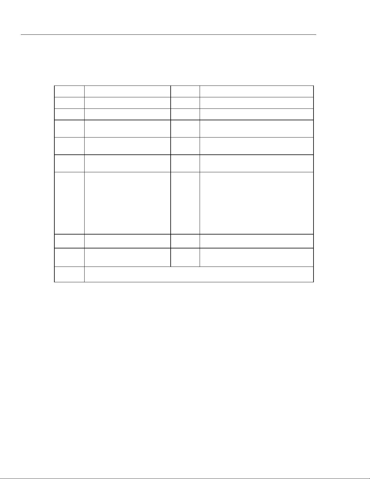
General Specifications
Maximum voltage between any
terminal and earth ground ........................................... 1000 V rms
WFuse for mA inputs .................................................. 440 mA, 1000 V FAST Fuse
WFuse for A inputs ..................................................... 11 A, 1000 V FAST Fuse
Display ........................................................................... 6000 counts, updates 4/sec (19,999 counts in high-resolution
mode).
Altitude
Operating.................................................................... 2,000 meters
Storage ....................................................................... 10,000 meters
Temperature
Operating.................................................................... -15 °C to 50 °C
Storage ....................................................................... -40 °C to +85 °C (without battery)
-40 °C to +60 °C (with battery)
Temperature coefficient ............................................... 0.05 X (specified accuracy) / °C (<18 °C or >28 °C)
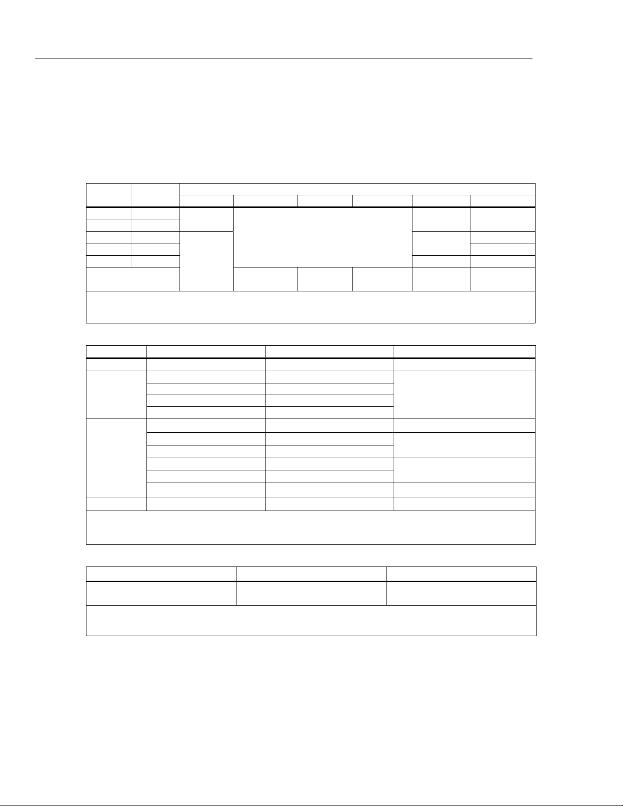
Electromagnetic Compatibility (EN 61326-1:2005) .... In an RF field of 3 V/M, accuracy = specified accuracy +20
counts, except 600 μA dc range total accuracy = specified
accuracy +60 counts. Temperature not specified
Relative Humidity.......................................................... 0 % to 80 % (0 °C to 35 °C)
0 % to 70 % (35 °C to 50 °C)
Battery Type .................................................................. 3 AAA Alkaline batteries, NEDA 24A IEC LR03
Approved Batteries....................................................... Duracell Procell MN2400 LR03
Duracell Plus MN2400 LR03
Varta Max Tech No. 4703
Varta Industrial Alcaline No. 4003 (min. operating temperature is -
10 °C)
Eveready Energizer No. E92
Rayovac Alkaline AAA (U.S. Type)
Panasonic LR03XWA
Battery Life .................................................................... 400 hrs typical without backlight (Alkaline)
Vibration ........................................................................ Per MIL-PRF-28800 for a Class 2 instrument
Shock ............................................................................. 1 Meter drop per IEC 61010 (3 Meter drop with holster)
Size (H x W x L) ............................................................. 4.57 cm x 10.0 cm x 21.33 cm (1.80 in x 3.95 in x 8.40 in)
Size with Holster ........................................................... 6.35 cm x 10.0 cm x 19.81 cm (2.50 in x 3.95 in x 7.80 in)
Weight ............................................................................ 567.8 g (1.25 lb)
Weight with Holster and Flex-Stand............................ 769.8 g (1.70 lb)
Safety Compliance........................................................ Complies with ANSI/ISA S82.01-2004, CAN/CSA C22.2 61010-1-
04 to 600 V Measurement Category IV. Licensed by TÜV to
EN61010-1, Pollution degree 2
Certifications ................................................................. CSA, TÜV, P, , ATEX, IECEx
IP Rating ........................................................................ 67 (Non-operating. Protected against dust and the effect of
immersion up to 1 m for 30 min.)