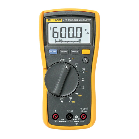
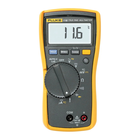
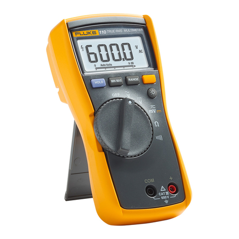
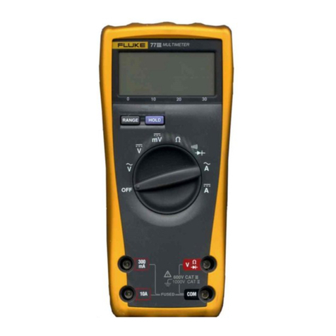
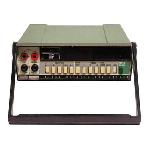
Fluke 8021B User manual

NOTE
This manual documents the Model 8021 B and its assemblies at the revision levels
shown in Appendix A. If your instrument contains assemblies with different revision
letters, it will be necessary for you to either update or backdate this manual. Refer to
the supplemental change/errata sheet for newer assemblies, or the backdating sheet
in Appendix Afor older assemblies.
8021 B
Digital
Multimeter
Instruction Manual
P/N 616037
July 1981
Rev. 15/82
©1982, John Fluke Mfg. Co., Inc., all rights reserved. Litho in U.S.A. IFLUKE

Dear Customer:
Congratulations! We at Fluke are proud to presentyou with theModel 8020B
Multimeter, This instrument represents the very latest in integrated circuit and
display technology. As aresult, the end product is arugged and reliable
instrument whose performance and design exhibit the qualities of afinely
engineered lab instrument.
To fully appreciate and protect your investment, we suggest you take afew
moments to read the manual. As always, Fluke stands behindyour802IB with a
full 2year warranty and aworldwide service organization. If the need arises,
please don't hesitate to call on us.
Thank you for your trust and confidence.
John Fluke Mfg. Co., Inc.

8021 B
Table of Contents
SECTION TITLE PAGE
1INTRODUCTION AND SPECIFICATIONS 1-1
1-1. INTRODUCTION W
1-3. ACCESSORIES 1-2
1-
5. SPECIFICATIONS 1-2
2OPERATING INSTRUCTIONS 2-1
2-
1. INTRODUCTION 2-1
2-3. PREPARING FOR OPERATION 2-1
2-4. Unpacking 2-1
2-7. Battery and/or Fuse Installation/ Replacement 2-1
2-9. PHYSICAL FEATURES 2-2
2-11. OPERATING NOTES 2-2
2-13. Input Overload Protection 2-6
2-15. Input Connections to COMMON 2-6
2-17. Fuse Check 2-6
2-19. Fuse Replacement 2-7
2-21. The Display 2-7
2-25. OPERATION 2-8
2-27. INITIAL CHECK-OUT PROCEDURE 2-15
2-29. MEASUREMENT TECHNIQUES 2-16
2-31. AC Measurements 2-16
2-33. Voltage AC/ DC 2-16
2-36. Current AC/ DC 2-16
2-
40. Resistance 2-19
243. Continuity 2-19
3
THEORY OF OPERATION 3-1
3-
1. INTRODUCTION 3-1
3-3. OVERALL FUNCTIONAL DESCRIPTION 3-1
3-8. BLOCK DIAGRAM ANALYSIS 3-1
3-9. A/D Converter 3-1
3-18. Input Signal Conditioners 3-6
/(continued on page ii)

8021 B
TABLE OF CONTENTS, continued
SECTION TITLE PAGE
4MAINTENANCE 4-1
4-1. INTRODUCTION 4-1
4-3. SERVICE INFORMATION 4-1
4-7. GENERAL INFORMATION 4-1
4-8. Access Information 4-1
4-17. Cleaning 4-5
4-19. Battery/ Backup Fuse Replacement 4-5
4-21. PERFORMANCE TEST 4-6
4-23. Initial Procedure 4-6
4-25. Display Test 4-6
4-27. Resistance Test 4-6
4-29. Continuity Test 4-7
4-31. DC Voltage Test 4-7
4-33. AC Voltage Test 4-8
4-35. DC Current Test 4-9
4-37. CALIBRATION 4-9
4-
40. TROUBLESHOOTING 4-10
5LIST OF REPLACEABLE PARTS 5-1
5-
1. INTRODUCTION 5-1
5-
4. HOW TO OBTAIN PARTS .5-1
6OPTIONS AND ACCESSORIES 6-1
6-
1. INTRODUCTION 6-1
6-3. DELUXE CARRYING CASE (C-90) 6-1
6-5. TEMPERATURE PROBES (80T-150C and 80T-150F) 6-1
6-6. Introduction 6-1
6-8. Specifications 6-1
6-9. CURRENT TRANSFORMER (801-600) 6-4
6-10. Introduction 6-4
6-12. Specifications 6-4
6-13. HIGH VOLTAGE PROBE (80K-6) 6-4
6-14, Introduction 6-4
6-16. Specifications 6-4
6-17. HIGH VOLTAGE PROBE (80K-40) 6-4
6-18. Introduction 6-4
6-20. Specifications 6-4
6-21. HIGH FREQUENCY PROBE (83RF) 6^
6-22. Introduction 6-4
6-24. Specifications... 6-4
6-25. HIGH FREQUENCY PROBE (85RF) 6-5
6-26. Introduction 6-5
6-28. Specifications 6-5
6-29. BATTERY ELIMINATOR (A81) 6-5
6-31. CURRENT SHUNT (80J-10) 6-6
(continued on page Hi)

8021
B
TABLE OF CONTENTS, continued
SECTION TITLE PAGE
6-32. Introduction 6-6
6-34. Specifications 6-6
6-35. AC/ DC CURRENT PROBE (Y8100) 6-6
6-36. Introduction 6-6
6-38. Specifications 6-6
6-39. AC CURRENT TRANSFORMER (Y8101) 6-7
6-40 Introduction 6-7
6-42. Specifications 6-7
6-43. SAFETY DESIGNED TEST LEAD SET (Y8132) .... 6-7
6-45. DELUXE TEST LEAD SET (Y8134) 6-7
6-47. SLIM FLEX TEST LEAD SET (Y8140) 6-7
7SCHEMATIC DIAGRAMS 7-1
AMANUAL CHANGE AND BACKDATING INFORMATION .A-1
il’l/lV


8021 B
List of Tables
TABLE TITLE PAGE
1-1. 802 IB Accessories
1-
2. 802 IB Specifications i-2
2-
1. Controls, Indicators and Connectors 2-4
2-2. Model 802 IB Overload Limits 2-7
2-3. Voltage/ Current Capability of Resistance Ranges 2-21
4-1. List of Recommended Test Equipment 4-2
4-2. Resistance Checks •4-7
4-3. DC Voltage Checks *4-8
4-4. AC Voltage Test .4-9
4-5. DC Current (mA) Checks —4-9
4-
6. Troubleshooting Guide 4-1!
5-
1. 802 IB Final Assembly 5-3
5-2. A1 Main PCB Assembly •5-6
5-3. A2 Annunciator PCB Assembly 5-10
5-
4. Federal Supply Codes for Manufacturers 5-12
6-
1. A81 Model vs Input Power 6-5


8021
B
List of Illustrations
FIGURE TITLE PAGE
2-1. Removing the Battery Cover 2-3
2-2. Battery Removal ••2-3
2-3. Controls, Indicators and Connectors 2-4
2-4. DC Volts (DC V) Operation 2-9
2-5. AC Volts (AC V) Operation 2-10
2-6. Direct Current (DC m.A) Operation 2-11
2-7. Alternating Current (AC mA) Operation 2-12
2-9. Resistance (fi) Operation 2-14
2-10. Waveform Conversion 2-17
2-11. Voltage Measurement Error Calculations (Loading Error) .2-18
2-
12. Current Measurement Error Calculations 2-20
3-
1. Model 802 IB Simplified Block Diagram 3-2
3-2. Dual Slope A/DConverter 3-4
3-
3. Input Signal Conditioners 3-8
4-
1. Calibration Adjustment Locations 4-3
4-
2. LCD Display Assembly 4-4
5-
1. 8021 BFinal Assembly 5-5
5-2. A! Main PCB Assembly 5-9
5-
3. A2 Annunciator PCB Assembly 5-1
!
6-
1. Model 802 IB Accessories 6-2
vii/viii


8021 B
Section 1
Introduction and Specifications
1-1. INTRODUCTION
1-2. Your John Fluke Model 8021 Bis apocket-size digital multimeter that is ideally
suited for application in the field, lab, shop or home. Your 8021 Boffers all standard VOM
measurement functions: AC and DC volts. Alternating and Direct Current, and
Resistance. In addition, the 8021 Bfeatures acontinuity function, which provides an
immediate audible indication when continuity is detected. Some of the features of your
instrument are:
•Ahigh contrast 3-1 /2digit liquid crystal display, that can be easily read from across
the room. No more worries about bent needles, parallax, etc.
•Each range has:
Full auto-polarity operation
Overrange indication
Effective protection from overloads and transients
•Dual slope integration measurement technique to ensure fast, accurate, noise-free
measurements.
•Long term calibration stability -2years. Easy calibration -few adjustments.
•Lightweight -369 grams (13 ounces).
•Up to 200 hours of continuous operation can be expected from asingle,
inexpensive, 9V, alkaline battery (transistor radio/ calculator type).
•Low battery voltage automatically detected and displayed.
•Line operation is possible using aModel A81 Battery Eliminator (see Section 6,
Accessories).
•Protected test leads offer less chance of measured signal exposure at the DM M
input terminals than standard banana test lead tips.
•Afull line of accessories that extend the range and scope of your instrument.
1-1

8021
B
1-3. ACCESSORIES
1-4. Table 1-1 lists the accessories available for use with the Model 802 IB. Detailed
information about each accessory is provided in Section 6.
1-5. SPECIFICATIONS
1-6. Table 1-2 lists the 8021 Bspecifications. These specifications assume a2year
calibration cycle and an operating temperature of 18°C to 28°C (64°F to 82°F) at a
relative humidity of up to 90% unless otherwise noted.
Table 1-1. 8021 BAccessories
ACCESSORY DESCRIPTION
A81 Battery Eliminator
C-90 Vinyl Carrying Case
80T-150C Temperature Probe °C
80T-150F Temperature Probe °F
801-600 Current Transformer 2" jaws
80K-6 High Voltage Probe
80K-40 High Voltage Probe
80J-10 Current Shunt
83RF High Frequency Probe
85RF High Frequency Probe
Y8100 AC/DC Current Probe
Y8101 Current Transformer 7/16” jaws
Y8132 Safety Designed Test Lead Set
Y8134 Deluxe Test Lead Set
Y8140 Slim Flex Test Lead Set
Table 1-2. 8021 BSpecifications
The following specifications assume a2-year calibration cycle and an
operating temperature of 18°C to 28°C (64° Fto 82° F) at arelative humidity up
to 90%, unless otherwise noted.
FUNCTIONS DC Volts, AC Volts, DC Current, Resistance
DC VOLTS
RANGE RESOLUTION ACCURACY FOR 2YEARS
±200 mV 100 (N
±2V 1mV
±20V 10 mV ±{.25% of reading +1digit)
±200V 100 mV
±1000V IV
1-2

802 IB
Table 1-2. 8021 BSpecifications (cont)
Overvoltage Protection 1000V dc or peak ac on all ranges.
Input Impedance 10 MO, all ranges.
Normal Mode Rejection Ratio >60 dB at 50 Hz and 60 Hz.
Common Mode Rejection
Ratio (1 kO unbalance) >100 dB at dc, 50 Hz and 60 Hz.
AC VOLTS
RANGE RESOLUTION ACCURACY
45 Hz to 450 Hz
200 mV 100 (M
2V 1mV
20V 10 mV ±(1% of reading +3 digits)
200V 0.1V
750V IV
Overload Protection 750V rms or 1000V peak continuous, except
200 mV ac ranges (15 seconds maximum
above 300V rms ac).
Common Mode Noise Rejection
Ratio (1 kO unbalance) >60 dB at 50 Hz and 60 Hz.
Volt-Hz Product 107max (200V @50 kHz).
Input Impedance ..
.' 10 MQ in parallel with <100 pf.
DC CURRENT
RANGE RESOLUTION ACCURACY FOR 2YEARS BURDEN
VOLTAGE
2mA
20 mA
200 mA
2000 mA
1/jA
10 fjA
100 fjA
1mA
±{1% of reading +1digit)
0.9V rms max
Overload Protection 2A/250V fuse, in series with a3A/600V fuse.
RESISTANCE
RANGE RESOLUTION ACCURACY
FOR 2YEARS
FULL-
SCALE
VOLTAGE
MAXIMUM
TEST
CURRENT
2000
2kQ
20 kO
200 kO
2000 kO
20 MO
0.10
10
10O
1000
1kO
10 kO
±(0,3% of reading +3 digits) <0.25V
>1.0V
<0.25V
>0.7V
<0.25V
>.7V
.35 mA
1.1 mA
13 M
13 jjA
0.13 //A
0.13 /iA
±(0,2% of reading +1 digit)
±(2% of reading +1 digit)
1-3

8021
B
Table 1-2. 8021 BSpecifications (cont)
Overload Protection 500V dc/ac rms on all ranges (15 seconds
maximum above 300 volts).
Open Circuit Voltage Less than 1.5V on all ranges except 2kQ
range is less than 3.5V.
Diode Test 2kQ. 200 kQ, and 20 MQ ranges supply
enough voltage to turn on junctions
allowsing a"Diode Test". The 2kQ range is
the preferred range and is marked with a
diode symbol (>*). 200Q, 20 kQ, and 2000 kQ
ranges can make in-circuit measurements
without turning on silicon junctions.
CONTINUITY (for Passive Circuit Testing)
Ranges Ail resistance ranges. (2 kQ range
recommeded for lowest resistance
threshold)
Indication
CONTINUITY Audible tone
OPEN CIRCUIT No audible tone
Response Time 50 ys (Minimum duration of continuity or
open to toggle audible tone) on 2kQ range.
Pulse stretcher holds tone on or off for
approximately 200 ms,
Overload Protection 500V dc/rms ac on all ranges. (15 sec. max.
above 300V.)
AC CURRENT
RANGE RESOLUTION ACCURACY FOR 2YEARS BURDEN
VOLTAGE
45 Hz TO 450 Hz
2mA 1//A ±(3% of reading +3 digits)
20 mA 10 fjA
±(2% of reading +3 digits)
200 mA 100 a/A
2000 mA 1mA
Overload Protection 2A/250V fuse, in series with a 3A/600V fuse.
ENVIRONMENTAL
Temperature 0°C to 50°C (32°F to 122°F) operating.
-35° Cto +60° C(-31 °F to 140°F) storage.
Relative Humidity 0to80%, 0°C to35°C (32-95°F) on 2000 kQ
and 20 MQ ranges. 0to 90%, 0°C to 35° C
(32-95° F) on all other ranges. 0to 70%, 35° C
to50° C(95-1 22° F).
1-4

8021
B
Table 1-2. 8021 BSpecifications (cont)
Temperature Coefficient
GENERAL
Protection Class 2
Maximum Common Mode
Voltage
BATTERY LIFE
Alkaline
Carbon Zinc —
BATTERY INDICATOR ....
Display
Size ......
Weight
<0.1 times the applicable accuracy
specification per °C for 0°C to 18°C and
28° Cto 50° C(32° F to 64.4° Fand 82.4° F to
122°F).
Relates solely to insulation or grounding
properties defined in IEC 348.
500V dc/rms ac.
Single 9V battery, NEDA 1604.
200 hours typical.
100 hours typical.
”BT” on display illuminates when
approximately 20% of battery life remains.
3'/z digit LCD (2,000 count), autozero,
autopolarity.
LxWxH: 18.0 cm x8.6 cm x4.5 cm
(7.1 in x3.4 in x1.8 in)
0.37 kg. (13 oz)
1-5/1 -6


8021
B
Section 2
Operating Instructions
2-1. INTRODUCTION
2-2. To fully utilize the measurement capabilities of your 8021 Babasic understanding of
its measurement techniques and limitations is required. This section of the manual
provides that information. For additional application or operation literature, write or call
the John Fluke Mfg. Co., Inc.; telephone (206) 342-6300.
2-3. PREPARING FOR OPERATION
2-4. Unpacking
2-5. Your 8021 Bwas packed and shipped in an especially designed protective container.
This manual, the multimeter, one 9V battery, and two test leads (one red and one black)
should be packed in the shipping container. Check your shipment thoroughly. If anything
is wrong with your shipment, or if your instrument was damaged during shipping, contact
the place of puchase immediately. If satisfaction is not obtained, contact the nearestJohn
Fluke Service Center. Alist of these service centers is located at the end of this of this
manual.
2-6. If reshipment is necessary, please use the original shipping container. If the original
container is not available, anew one can be obtained from the John Fluke Mfg. Co., Inc.
Please state the instrument model number when requesting anew shipping container.
2-7. Battery and/or Fuse Instailation/Replacement
2-8. Your 802 IB is designed to operate on asingle, inexpensive, 9V battery of the
transistor radio/calculator variety (NEDA 1604). When you receive your 8021 B, the
battery will not be installed in the DMM. Once the battery is installed, you can expect a
typical operating life of up to 200 hours with an alkaline battery or 100 hours with a
carbon-zinc battery. When the battery has exhausted about 80% of its usefule life, the BT
indicator will appear in the upper left corner of the display. Your 802 IB will operate
properly for at least 20 hours after BT appears. Use the following procedure to install or
replace the battery or Fuse FI.
CAUTION
To ensure operation within the accuracy specifications, the battery should be
replaced when the voltage measured at the center of the battery eliminator
connector falls below -3.00 volts (with respect to the COMMON input). If the
2-1

8021
B
battery voltage falls to a point where the "BT" is displayed and the digital
display is inactive or no longer responds to asignal input, the battery should be
replaced immediately to prevent damage to the LCD.
WARNING
TO AVOID ELECTRICAL SHOCK HAZARDS REMOVE THE INPUT SIGNAL
AND TEST LEADS FROM THE INPUT TERMINALS, AND SET THE POWER
SWITCH TO OFF BEFORE OPENING THE BATTERY COMPARTMENT.
1. Set the 802 IB power switch to OFF.
2. Remove the test leads from external circuit connections and from the 8021
B
input terminals.
3. Open the battery compartment on the bottom of the 802 IB using the method
shown in Figure 2-1.
4. Tilt the battery out as shown in Figure 2-2.
5. If fuse FI is to be replaced, use apointed tool such as aprobe tip or small
screwdriver to pry FI from its holder. Replace the defective fuse with fuse type
AGX2. (instruments that accommodate metric fuses use type F).
6. Disconnect the battery clip from the battery terminals.
7. Press the battery clip onto the replacement battery and return both to the
battery compartment.
8. Make sure the battery leads are routed by the broad side of the battery and fully
within the confines of the battery compartment before sliding the cover into place.
WARNING
DO NOT OPERATE THE 8021 BUNTIL THE BATTERY COVER IS IN PLACE
AND FULLY CLOSED.
2-9. PHYSICAL FEATURES
2-10. Before using your 8021 Bwe suggest that you take afew minutes to get acquainted
with your instrument. All of the externally accessible physical features of 802 1Bare shown
in Figure 2-3 and described in Table 2-1. Locate each feature on your 8021 Bas you read
the description.
2-11. OPERATING NOTES
2-12. The following paragraphs will familiarize you with the capabilities and limitations
of your Model 802 IB and instruct you in routine operator maintenance.
2-2

8021
B
Figure 2-1. Removing the Battery Cover
Figure 2-2. Battery Removal
2-3

8021 B
Table 2-1. Controls, Indicators, and Connectors
ITEM
NO. NAME FUNCTION
1Display A31/2 digit display (1999 max) with
decimal point and minus polarity
indication. Used to indicate measured
input values, overrange condition and
iow battery condition.
2Battery Eliminator
Connector
An external input power connector for
use with the Mode! A81 Battery
Eliminator accessory. (A81 is available
in avariety of voltage and plug
configurations. See Section 6.)
3Battery Compartment
and Cover
Cover for the 9V battery and the
current-protection fuses. Refer to
Figure 2-1 for battery cover removal
instructions.
WO Input Connector Protected test lead connector used as
the high input for all voltage,
resistance, and continuity measure-
2-
Other manuals for 8021B
1
Table of contents
Other Fluke Multimeter manuals

Fluke
Fluke 27/FM User manual

Fluke
Fluke 3000 FC User manual

Fluke
Fluke 28 II Ex Use and care manual

Fluke
Fluke 233 User manual

Fluke
Fluke 12B/18 User manual

Fluke
Fluke 110 Use and care manual

Fluke
Fluke 76 Assembly instructions

Fluke
Fluke 110 PLUS User manual

Fluke
Fluke 27-II Use and care manual

Fluke
Fluke 8808A User manual