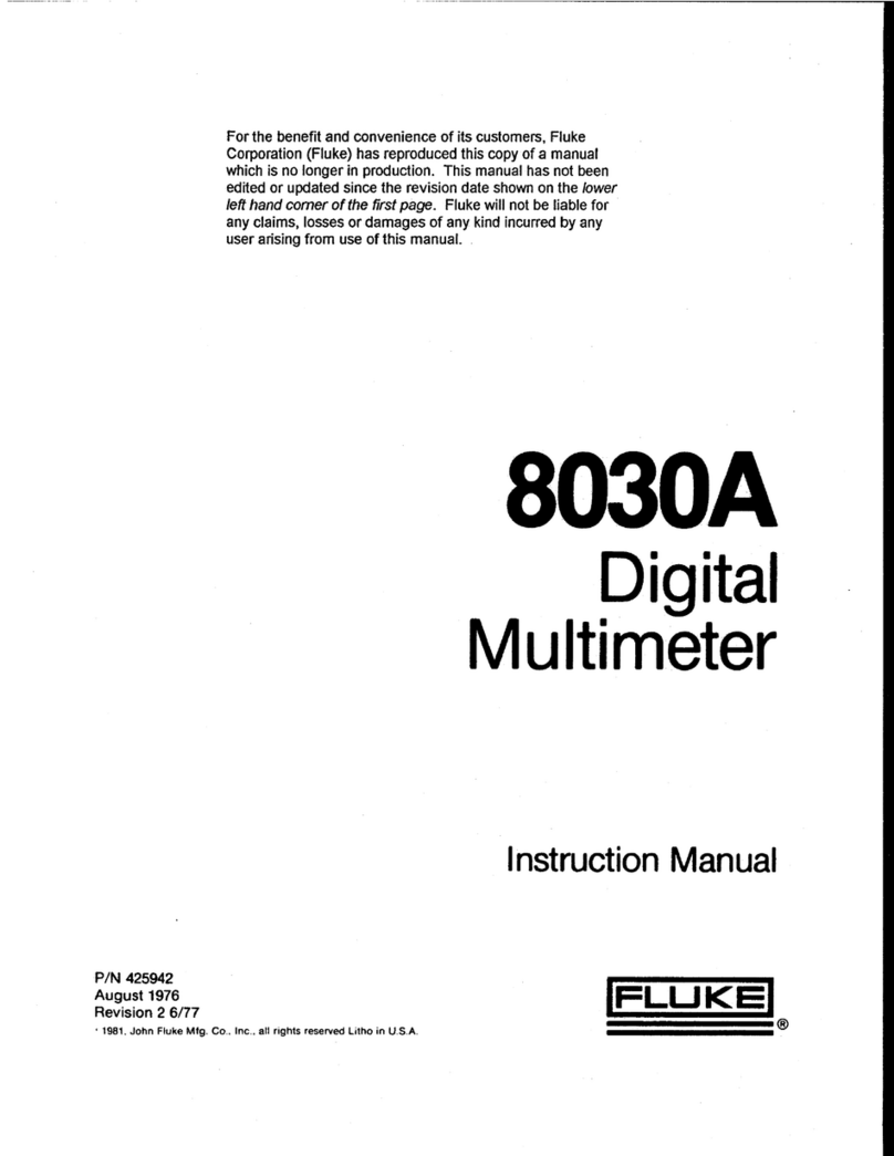
Fluke 8600A User manual

For the benefit and convenience of its customers, Fluke
Corporation (Fluke) has reproduced this copy of a manual
which is no longer in production. This manual has not been
edited or updated since the revision date shown on the
lower left hand corner of the first page. Fluke will not be
liable for any claims, losses or damages of any kind
incurred by any user arising from use of this manual.
8600A
Digital
Multimeter
Instruction Manual
P/N 391409
NOVEMBER 1974 Rev. 3, 1/77
®1977 John Fluke Mfg. Co., Inc., All rights reserved. Litho in USA. Iflukei®

WARRANTY
Notwithstanding any provision of any agreement the following warranty is exclusive:
The JOHN FLUKE MFG. CO., INC., warrants each instrument it manufactures to be free from defects in material and
workmanship under normal use and service for the period of 1-year from date of purchase. This warranty extends only
to the original purchaser. This warranty shall not apply to fuses, disposable batteries (rechargeable type batteries are
warranted for 90-days), or any product or parts which have been subject to misuse, neglect, accident, or abnormal
conditions of operations.
In the event of failure of a product covered by this warranty, John Fluke Mfg. Co., Inc., will repair and calibrate an
instrument returned to an authorized Service Facility within 1year of the original purchase; provided the warrantor's
examination discloses to its satisfaction that the product was defective. The warrantor may, at its option; replace the
product in lieu of repair. With regard to any instrument returned within 1year of the original purchase, said repairs or
replacement will be made without charge. If the failure has been caused by misuse, neglect, accident, or abnormal
conditions of operations, repairs will be billed at anominal cost. In such case, an estimate will be submitted before
work is started, if requested.
THE FOREGOING WARRANTY IS IN LIEU OF ALL OTHER WARRANTIES, EXPRESS OR IMPLIED,
INCLUDING BUT NOT LIMITED TO ANY IMPLIED WARRANTY OF MERCHANTABILITY, FITNESS,
OR ADEQUACY FOR ANY PARTICULAR PURPOSE OR USE. JOHN FLUKE MFG CO.. INC., SHALL
NOT BE LIABLE FOR ANY SPECIAL, INCIDENTAL, OR CONSEQUENTIAL DAMAGES, WHETHER IN
CONTRACT, TORT, OR OTHERWISE.
If any failure occurs, the following steps should be taken:
1. Notify the JOHN FLUKE MFG. CO., INC,, or nearest Service facility, giving full details of the difficulty, and
include the model number, type number, and serial number. On receipt of this information, service data, or
shipping instructions will be forwarded to you.
2. On receipt of the shipping instructions, forward the instrument, transportation prepaid. Repairs will be
made at the Service Facility and the instrument returned, transportation prepaid.
SHIPPING TO MANUFACTURER FOR REPAIR OR ADJUSTMENT
All shipments of JOHN FLUKE MFG. CO., INC., instruments should be made via United Parcel Service or "Best Way”*
prepaid. The instrument should be shipped in the original packing carton; or if it is not available, use any suitable
container that is rigid and of adequate size. If asubstitute container is used, the instrument should be wrapped in paper
and surrounded with at least four inches of excelsior or similar shock-absorbing material.
CLAIM FOR DAMAGE IN SHIPMENT TO ORIGINAL PURCHASER
The instrument shoulo be thoroughly inspected immediately upon original delivery to purchaser. All material in the
container should be checked against the enclosed packing list. The manufacturer will not be responsible for shortages
against the packing sheet unless notified immediately. If the instrument is damaged in any way, aclaim should be filed
with the carrier immediately. (To obtain aquotation to repair shipment damage, contact the nearest Fluke Technical
Center.) Final claim and negotiations with the carrier must be completed by the customer.
The JOHN FLUKE MFG. CO., INC, will be happy to answer all applications or use questions, which will enhance your
use of this instrument. Please address your requests or correspondence to: JOHN FLUKE MFG. CO., INC., P.O. BOX
C9090, EVERETT, WASHINGTON 98206, ATTN: Sales Dept. For European Customers: Fluke (Holland) B.V., P.O. Box
5053, 5004 EB, Tilburg, The Netherlands.
*For European customers, Air Freight prepaid.
John Fluke Mfg. Co., Inc., P.O. Box C9090, Everett, Washington 98206
Rev. 6/81

8600A
Table of Contents
SECTION TITLE PAGE
1INTRODUCTION AND SPECIFICATIONS 1-1
1-1. INTRODUCTION 1-1
1-
9. SPECIFICATIONS 1-2
2OPERATING INSTRUCTIONS 2-1
2-
1. INTRODUCTION 2-1
2-3. SHIPPING INFORMATION 2-1
2-6. INPUT POWER 2-1
2-9. RACK INSTALLATION 2-1
2-11. OPERATING FEATURES 2-1
2-13. OPERATING NOTES 2-3
2-15. Option Information 2-3
2-17. Fuses 2-3
2-19. Overrange Indication 2-3
2-21. Input Overload Protection /l\ 2-3
2-23. Autoranging 2-3
2-
25. OPERATION 24
3THEORY OF OPERATION 3-1
3-
1. INTRODUCTION 3-1
3-3. OVERALL FUNCTIONAL DESCRIPTION 3-1
34. Introduction 3-1
3-6. Input Signal Conditioners 3-1
3-12. A/D Converter 3-2
3-15. Control and Display 3-2
3-18. Data Output Unit (DOU) 3-3
3-20. CIRCUIT DESCRIPTION 3-3
3-22. Input Signal Conditioners 3-3
3-37. A/D Converter 3-6
342. Control and Display 3-8
(continued on page iij

8600A
TABLE OF CONTENTS,continued
SECTION TITLE PAGE
4MAINTENANCE 4-1
4-1. INTRODUCTION 4-1
4-3. SERVICE INFORMATION 4-1
4-6. GENERAL MAINTENANCE 4-2
4-7. Access/Disassembly 4-2
4-10. Cleaning 4-2
4-12. Fuse Replacement 4-2
4-14. PERFORMANCE TESTS 4-2
4-16. DC Voltage Test 4-2
4-18. Ohms Test 4-2
4-20. DC Current Test 4-3
4-22. AC Voltage Test 4-3
4-24. CALIBRATION 4-3
4-25. Introduction 4-3
4-27. DC Volts Calibration 4-3
4-29. Ohms Calibration 4-5
4-31. AC Volts Calibration 4-5
4-33. TROUBLESHOOTING 4-5
4-35. Initial Troubleshooting 4-6
4-38. Power Supply Checks 4-6
4-
40. Fault Area Isolation 4-7
5LIST OF REPLACEABLE PARTS 5-1
5-
1. INTRODUCTION 5-2
5-4. HOW TO OBTAIN PARTS 5-2
5-
7. USE CODE EFFECTIVITY LIST 5-2
6OPTIONS AND ACCESSORY INFORMATION 6-1
6-
1. INTRODUCTION 6-1
6-3. CARRY CASE (C80) 6-1
6-5. CARRYING CASE (C86) 6-1
6-7. FRONT PANEL DUST COVER (M00-100-714) 6-1
6-9. RACK MOUNTING KITS 6-1
6-10. Introduction 6-1
6-12. Installation Procedure 6-2
6-16. DELUXE TEST LEAD KIT (A80) 6-2
6-18. CURRENT PROBE, CLAMP-ON (801-600) 64
6-19. Introduction 64
6-21. Operation 64
6-23. HIGH VOLTAGE PROBE (80K40) 6-5
6-24. Introduction 6-5
6-26. Specifications 6-5
6-27. Operation 6-5
6-29. HIGH FREQUENCY PROBE (80RF-1) 6-6
6-30. Introduction 6-6
6-32. Specifications 6-6
(continued on page Hi)
ii

8600A
TABLE OF CONTENTS, continued
SECTION TITLE PAGE
6-33. Operating Notes 6-6
6-36. Operation 6-6
6-38. Theory of Operation 6-7
641. Maintenance 6-7
6-50. HIGH FREQUENCY PROBE (8 1RF) 6-9
6-51. Introduction 6-9
6-53. Specifications 6-9
6-54. Operation 6-9
6-56. TEMPERATURE PROBE (80T-1 50) 6-9
6-59. BATTERY PACK, OPTION -01 6-9
6-60. Introduction 6-9
6-62. Specifications 6-9
6-64. Operation 6-9
6-66. Theory of Operation 6-10
6-69. Maintenance 6-10
6-80. DATA OUTPUT UNIT (OPTION -02) 6-11
6-81. Introduction 6-11
6-83 Specifications 6-11
6-85 Operation 6-11
7GENERAL INFORMATION 7-1
8SCHEMATIC DIAGRAMS 8-1
iii1/77

8600A
List of Illustrations
FIGURE TITLE PAGE
1-
1. Model 8600A Outline Drawing 1-5
2-
1. 8600A Controls, Indicators and Connectors 2-2
3-
1. Overall Functional Block Diagram 3-2
3-2. Timing Diagram for Dual-Slope A/D Conversion 3-3
3-3. Ohms Converter Block Diagram 3-4
34. AC Converter Block Diagram 3-5
3-
5. A/D Converter Block Diagram 3-7
4-
1. Calibration Adjustment Locations 44
4-2. Troubleshooting Flow Chart 4-7
4-3. A/D Converter Output Signal 4-9
4-
4A/D Converter Control Signals 4-10
5-
1. 8600A Final Assembly 54
5-2. Front Panel and Main PCB Assembly (8600A Line Power) 5-9
5-3. Front Panel and Main PCB Assembly (8600A-01 Battery Power) 5-14
54. Display PCB Assembly 5-15
5-5. Battery Power Supply PCB Assembly (—01 Option) 5-17
5-6. AC Converter PCB Assembly 5-20
5-7. Ohms Converter Assembly 5-22
5-8. Input Divider PCB Assembly 5-23
5-9. DOU PCB Assembly —02 Option 5-25
(continued on page v)
iv 1/77

8600A
LIST OF ILLUSTRATIONS,continued
FIGURE title page
6-1. Model C80 Carrying Case g_2
6-2. Model C86 Carrying Case 6_2
6-3. Rack Mounting Kits, Offset and Center Mount 6-3
6-4. Rack Mounting Kit, Side-By-Side Mounting 6-4
6-5. Deluxe Test Lead Kit (A80) 6-4
6-6. AC Current Probe, Clamp-On (801-600)64
6-7. High Current Probe (80K40) 6-5
6-8. High Voltage Probe, Schematic 6-5
6-9. 80RF-1, High Frequency Probe 6-6
6-10. 80RF-1, Schematic 6-7
6-11. Low Frequency Response Check 6-7
6-12. High Frequency Response Check 6-8
6-13. High Frequency Probe (81 RF) 6-9
6-14. DOU Timing Diagram 6-12
8-1 .Front Panel and Main PCB Assembly (2 sheets) 8-3
8-2. Display PCB Assembly g_7
8-3. AC Converter PCB Assembly 8-9
84. Ohms Converter PCB Assembly 8-11
8-5.Battery Power Supply PCB Assembly (Option
-
01 )8-13
8-6.Data Output Unit PCB Assembly (Option
—
02)8-15
1/77 v

8600A
List of Tables
table title page
1-1. 8600A Options 1-1
1-2. 8600A Accessories 1-1
1-
3. Model 8600A Specifications 1-2
2-
1.8600A Controls, Indicators and Connections 2-2
2-
2. Basic Measurement Instructions 2-3
3-
1.Ohms Converter Operating Conditions 3-5
3-
2. AC Converter Relay Operation 3-5
4-
1. Required Test Equipment 4-1
4-2. DCV Performance Test 4-2
4-3. Ohms Performance Test 4-3
44. DC Current Performance Test 4-3
4-5. ACVPerformance Test 4-3
4-6. DC Volts Calibration Procedure 4-5
4-7. Ohms Calibration Procedure 4-5
4-8. AC Volts Calibration Procedure 4-6
4-9. Fault Area Indication 4-7
4-10. Input Divider Test 4-8
4-11 .Operation of U8 with Respect To A/D Converter 4-10
4-12. Range Information 4-11
6-1 .Rack Mounting Kits 6-2
6-2. 8600A Ranges For Current Probe (801-600) 6-5
6-
3. 8600ARanges For DC HV Probe (80K40) 6-6
64. DOU Data Identification 6-12
7-
1.List of Abbreviations &Symbols 7-2
7-2. Federal Supply Codes For Manufacturers 7-3
7-3. Fluke Technical Service Centers 7.7
74. International Service Center 7-7
7-5. Sales Representatives -Domestic 7-8
7-6. Sales Representatives -International 7-9
VI 1/77

8600A
Section 1
Introduction &Specifications
1-1. INTRODUCTION
1-2. The Model 8600A is acompact and light-weight
digital multimeter (DMM). It features a4!4 digit display,
push-button selection of range and function, auto polarity,
self locating decimal point, self zeroing to eliminate offset
uncertainties, and overload protection for all ranges. Auto-
ranging can be selected when the ac volts, dc volts or kil-
ohms functions are selected. Several options and accessor-
ies for the 8600A are available (see Section 6).
1-3. Push-button controls allow the selection of five ac
and dc voltage ranges, five ac and dc current ranges, and six
resistance ranges. The measurement capabilities of the
8600A range from 10 microvolts to 1199.9 volts ac and dc,
10 nanoamperes to 1.9999 amperes ac and dc, and 10
milliohms to 19.999 megohms.
14. The front-panel readout features a4!4 digit display
using light emitting diodes (LED’s). The display includes a
self locating decimal point and a+or -polarity indicator.
Full-scale readout is 19999 for all ranges and functions except
the 1200 volt ac and dc range, which is 11999. Ablinking
18888 readout indicates that the 8600A is being operated
in an overload condition and provides atest for all seg-
ments in the display.
1-5. Front panel input connectors are banana type and
provide separate connections for current, and volt-ohm
inputs. Both the current and volt-ohm inputs are referenced
to acommon input which is isolated from earth ground and
can operate at apotential of up to ±1000V dc or peak Vac
with reference to earth ground.
1-6. The overload features of the 8600Ainclude afused
current input and an overvoltage protected volt-ohm input.
This protection applies for any function and range selected.
1-7. Several options and accessories are available for use
with the 8600A. The options are listed and described in
Table 1-1 ,and must be specified at time of purchase. The
accessories are listed and described in Table 1-2. Accessories
are compatible with all options and can be ordered at time of
purchase or after purchase. Detailed information concerning
each option and accessory is given in Section 6of this manual.
Table 1-1. 8600A OPTIONS
MODEL NO DESCRIPTION
8600A-01
8600A-02
Basic unit w/battery option
Basic unit w/data output unit
Table 1-2. 8600A ACCESSORIES
MODEL NO. DESCRIPTION
C80 Vinyl Carrying Case w/strap
C86 Molded Hard-Shell Carrying Case
A80 Deluxe Test Lead Kit
801-600 Clamp-on AC Current Probe
(2A to 600A)
80K—40 High Voltage Probe; IkV to 40kV
81 RF RF Probe: 100kHz to 100 MHz
80RF-1 RF Probe 100 kHz to 500 MHz
M00-100-714 Front Panel Cover
M00-200-61
1
Rack Mount, Center
M00-200-612 Rack Mount, Offset Left or Right
M00-200-613 Rack Mount, Side-by-Side
1-8 Input power for the 8600A is switch selectable to
provide operation at either 115 Vac or 230 Vac, 50 Hz or
60 Hz. The 8600A will also operate from 100 Vac, 50 Hz
or 60 Hz, when in the 115V switch position. The 8600A-01
1/77 1-1

8600
A
(battery power option) is configured at the factory for
115 Vac, or 230 Vac, 50 Hz or 60 Hz line power operation.
The battery power option must not be operated from any
other line voltage or frequency than that for which it is
configured (see decal on bottom of case). The operation of
the front panel controls is the same for all power configu-
rations of the 8600A, 8600A-01, and 8600A-02 instruments.
1-9. SPECIFICATIONS
1-10. Specifications for the Model 8600A are presented
in Table 1-3, under headings of DC VOLTAGE, AC VOLTAGE,
DC CURRENT, AC CURRENT, OHMS, and GENERAL.
Specifications for each option are listed under the option
heading.
Table 1-3. MODEL 8600A SPECIFICATIONS
DC VOLTAGE
Ranges +200 mV, +2V,+20V,+200V, +1200V
Accuracy
:
6Months (15°C to 35°C)
200 mV range
2V, 20V, and 200V ranges ..
1200V range
Temperature Coefficient:
200 mV range
2V to 1200V ranges ....
Input Impedance:
+(0.001?'o of input +0.0005% of range)/°C
200 mV and 2V ranges . . .
20V, 200V and 1200V ranges 10 megohms
Normal Mode Rejection ...60 dB minimum @50 Hz, 60 Hz
Common Mode Rejection ...
either lead)
Zero Stability
Ranging
Polarity Automatic bipolar, +or —display
Overload +1200V dc or 1700V peak ac applied continuously to any
range.
Response Time to Rated Accuracy Within Range . . 1second maximum to displayed input
AC VOLTAGE
Ranges 200 mV, 2V, 20V, 200V, 1200V
Accuracy
:
6Months (15°Cto 35°C)
200 mV range
(100% to 1% of range)
30 Hz -50 Hz; +(0.5% of input +0.10% of range)
50 Hz -10 kHz; ±(0.2% of input +0.08% of range)
10 kHz -50 kHz; +(0.5% of input +0.10% of range)
50 kHz -100 kHz; +(0.5% of input +0.5% of range)
2V, 20V and 200V ranges ..
(100% to 1% of range)
50 Hz -10 kHz; +(0.2% of input +0.015% of range)
30 Hz -50 Hz and 10 kHz -50 kHz;
±(0.5% of input +0.025% of range)
50 kHz -100 kHz; ±(1.0% of input +0.05% of range)
1-2 1/77

8600A
Table 1-3. MODEL 8600A SPECIFICATIONS
1200V range (100% to 1% of range) 10V to 500V, 50 Hz -10 kHz; +(0.2% of input +0.03% of
range)
500V -1200V, 50 Hz -10 kHz; +(0.37% of input +0.03%)
or range)
10V to 1200V, 30 Hz to 50 Hz, 10 kHz to 20 kHz,
±(0.5% of input +0.08% of range)
Temperature Coefficient:
200 mV range ±(0.01 5% of input +0.005% of range)/°C
2Vto 1200V ranges ±(0.01% of input +0.002% of range)/°C
Input Impedance 2megohms shunted by less than 100 pf
Response Time to Rated Accuracy Within Range ..1.5 seconds maximum to displayed input
Overload 1200V rms, 1700V peak ac applied continuously to any
range -not to exceed 2x10⁷VHz product (20 kHz max at
1000V)
Ranging Full autoranging, or manual ranging
DC CURRENT
Ranges 200 /iA, 2mA, 20 mA, 200 mA, 2000 mA
Ranging Manual ranging
Accuracy: 6Months (1 5°C to 35°C)
All Ranges ±(0.1% of input +0.01% of range) on all ranges
Temperature Coefficient:
AI1 Ranges ±(0.003% of input +0.001% of range)/°C
Voltage Burden 0.25V maximum up to 200mA: 0.5V maximum up to 2A
Overload Protected to 2A on all ranges: fused above 2A
Response Time to Rated Accuracy Within Range ..1second maximum to displayed input
AC CURRENT
Ranges 200/uA, 2mA, 20 mA, 200 mA, 2000 mA
Ranging Manual ranging
Accuracy :6Months (15° Cto 35° C)
50 Hz -10 kHz; ±(0.3% of input +0.08% of range) all
ranges (except 2000 mA range 50 Hz -5kHz)
30 Hz -50 Hz; ±(0.6% of input +0.1% of range) all ranges
Temperature Coefficient:
All Ranges ±(0.01 5% of input +0.005% of range)/°C
Voltage Burden 0.25V maximum up to 200mA: 0.5V maximum at 2A
Overload Protected to 2A on all ranges, fused above 2A
Response Time 1sec. max. to rated accuracy
OHMS
Ranges 200J2, 2kS2, 20 k£2, 200 k£2, 2000 kS2, 20 MS2
Ranging Full autoranging, or manual ranging
1/77 1-3

8600A
Table 1-3. MODEL 8600A SPECIFICATIONS
Accuracy: 6Months (15°C to 35°C)
200£2 range ±<0.1% of input +0.015% of range)
2k£2 +(0.1% of input +0.005% of range)
20 k£2 to 2000 kfi ranges +(0.05% of input +0.005% of range)
20 M£2 +(0.2% of input +0.005% of range)
Temperature Coefficient:
2k£2 to 2000 k£2 ranges ±(0.003% of input +0.0005% of range)/ °C
200 £2 and 20 Mf2 range ±(0.005% of input +0.001% of range)/°C
Configuration Two wire
Overvoltage Protection 250V rms or dc, applied continuously
Maximum Open Circuit Voltage 5volts
Response Time:
200 £2 to 2000 kfi ranges 1second maximum to displayed input
20 M£2 range 4seconds maximum to displayed input
200£2 2k£2 20 kft 200 k£2 2000 k£2 20 M£2
1mA 1mA 100mA10/iA 1/tA 0.1/iA
GENERAL
Display Seven-segment LED .3" character height, automatic decimal
location
Size 8.55" wide x2.52" high x10.65" deep (See Figure 1-1
)
21.72 cm x6,40 cm x27,05 cm
Weight 3.5 lbs. (1.6 kg) line power, 4.5 lbs. (2.1 kg) with batteries
Operating Temperatures 0°Cto+50°C
Storage Temperature -40°Cto +75°C (-40°C to +60°C with batteries)
Humidity Range 80% RH, +5°C to +35°C
70% RH, +35°C to +50°
C
Overload Indication Flashing display of +18888 (built in segment test of LED display)
for out of range indication
Maximum Common Mode Voltage ±1000V, dc or peak ac
P°wer 100/1 15/230V ac ±10% 50 or 60 Hz, 7watts line powered
BATTERY PACK, OPTION -01 10 mtXS ba,ttry Powered
Continuous Operation 8 hours typical (6 hours minimum)
Charge Time 16 hours maximum (@< 30°C ambient to achieve full charge).
DATA OUTPUT UNIT (DOU), OPTION -02
Available Data Digits, polarity (both logic senses) ,range, and reference output
Data Coding 8-4-2-1 BCD positive true parallel
Logic Levels 1=+5V, 0=0V
Drive Capability All output can drive aminimum of two TTL loads.
(i.e. sink 3.2 mA)
Flags Busy, busy, and overload
Controls. External trigger (positive going edge trigger), and External
trigger enable
1-4 1/77

8600A
1-5/1-6


8600A
Section 2
Operating Instructions
2-1. INTRODUCTION
2-2. This section of the manual contains information re-
garding installation and operation of the Model 8600A DMM.
It is recommended that the contents of this section be read
and understood before any attempt is made to operate the
instrument. Should any difficulties arise during operation,
please contact your nearest John Fluke Sales Representative
or the John Fluke Mfg. Co., Inc.,P.O. Box43210, Mount-
lake Terrace, WA 98043; telephone (206) 774-2211. Alist
of Sales Representatives is located in Section 7of this manual.
2-3. SHIPPING INFORMATION
2-4. The 8600A is packaged and shipped in afoam-
packed container. Upon receipt of the instrument, a
thorough inspection should be made to reveal any possible
shipping damage. Special instructions for inspection and
claims are included in the shipping carton.
2-5. If reshipment of the instrument is necessary, the
original container should be used. If the original container
is not available, anew container can be obtained from the
John Fluke Mfg. Co., Inc. Please reference the instrument
model number when requesting anew shipping container.
2-6. INPUT POWER
2-7. The 8600A can be operated from 100, 115, or
230V ac 50 or 60 Hz power lines, as selected by line power
select switch S14. Before connecting the instrument to line
power, check and, if necessary, set the instrument for
operation at local line voltage as follows: (the following
procedure should be carried out only by qualified per-
sonnel)
CAUTION!
Refer to Section 6Option —01 for requirements
of line voltage change for 8600A -01 instruments.
a. Remove the phillips screw from the rear of the
instrument.
b. Remove the case; pull it straight back from the
front panel.
c. Locate the power selection switch; near the rear or
the main pcb assembly.
d. For 100 or 115V ac operation position the slide
switch so that 115 appears in the slide aperture.
For 230V/240V ac operation set the switch so 230
appears.
e. Replace the case and phillips screw.
2-8. The rear panel power input connector is athree-
prong, U-ground connector which permits the instrument to
be connected, via the power cord, to the appropriate line
power. The offset prong on this connector is connected to
the 8600A power supply, and should be connected, via the
power cord, to ahigh quality earth ground.
2-9. RACK INSTALLATION
2-10. The 8600A is designed for either bench-top use or
for installation in astandard 19-inch equipment rack using
an optional accessory rack mounting kit. Rack mounting
kits are available for left, right, center, or side-by-side
mounting of the 8600A. Information regarding installation
of the rack-mounting accessories is given in Section 6 under
Rack Installation.
2-11. OPERATING FEATURES
2-12. The location of all 8600A controls, indicators and
connectors are shown in Figure 2-1, and described in Table
2-1.
1/77 2-1

8600A
Figure 2-1. 8600A CONTROLS, INDICATORS AND CONNECTORS
Table 2-1 .8600A CONTROLS, INDICATORS AND CONNECTORS
FIG. 2-1
REF. NO. NAME FUNCTION
1INPUT Connectors Provides the input connections necessary to make current (MA), voltage
(V), or resistance (fi) measurements. All measurements are referenced to
the LO INPUT terminals.
2Digital Readout Provides a4'A digit display (19999 maximum) or the measured input. The
readout also includes aproperly positioned decimal point, and a+or —
sign for dc voltage and current measurements.
3POWER Switch Switches the instrument on or off. The instrument is turned on when the
switch is depressed.
4RANGE Switches Provide pushbutton selection of ranges which correspond to the selected
function (current, voltage, or resistance). The available ranges are:
Voltage: 200 MV, 2, 20, 200, 1200V and AUTO
Current: 200juA, 2, 20, 200, 2000 MA
Resistance: 200S2, 2, 20, 200, 2000k12, 20MS2, and AUTO
5FUNCTION Switches Provide pushbutton selection of one-of-five measurement functions; ACV,
AC MA, DCV, DC MA, or Kft.
6Input Power Connector Provides the means of connecting the instrument through the power cord
to the ac power line.
2-2 1/77

8600A
2-13. OPERATING NOTES
2-14. The following paragraphs describe various condi-
tions which should be considered before operating the
8600A.
2-15. Option Information
2-16. Supplementary information is necessary when
operating an 8600A which is equipped with one of the
available options. Detailed information regarding the opera-
tion of each available option is given in Section 6, Options
and Accessories.
2-17. Fuses
2-18. The 8600A is equipped with aline power fuse, and
acurrent overload fuse for the current measuring function.
The line fuse is located near the transformer on the inside of
the instrument. The following procedure should be carried
out only by qualified personnel. To gain access, remove ac
power, remove the retaining screw on the rear of the case
and remove the instrument from the case. When replace-
ment is necessary, use an AGC 1/8A fuse. The current in-
put fuse is located behind the front-panel MA INPUT ter-
minal, and is accessed by turning (ccw) and removing the
MA INPUT terminal. Use aJohn Fluke 376582 replace-
ment fuse or equivalent 2A fast-blo fuse (AGX) 1inch in
length.
2-19. Overrange Indication
2-20. The front panel display, in addition to providing a
measurement reading, is designed to serve as an overrange
indicator. When the full scale capability of the selected
range for any function is exceeded, the display will blink
while indicating a18888 reading. The presence of an
overrange indication does not necessarily mean that the
instrument is being exposed to adamaging input condition.
2-21. Input Overload Protection /j\
CAUTION
Exceeding the maximum input overload conditions
can damage the 8600A.
2-22. Each range and function of the 8600Ais equipped
with input overload protection. The maximum allowable
input overload conditions for each function and range are
given in Table 2-2.
2-23. Autoranging
2-24. Autoranging can be selected when the 8600A is
in the VDC, VAC, or K£2 functions. When the AUTO
pushbutton is depressed the 8600A will select the lowest
range that will display the value of the input signal without
causing an overrange indication. Autoranging stops when one
of the individual range pushbuttons is depressed.
Table 2-2. BASIC MEASUREMENT INSTRUCTIONS
8600A
DESIRED
MEASUREMENT SELECT
FUNCTION SELECT
RANGE INPUT
CONNECTION MAXIMUM
INPUT REMARKS
DC Volts DCV 200 MV, 2, 20
200, or 1200V V-n and V-J2LO 1200V dc or
1700V peak
ac, any range
Auto-polarity
Auto-ranging
DC Milliamperes DC MA 200 jUA, 2, 20
200 or 2000MA MA and MA LO* 2A (Fuse
Protected)
Manual-ranging
Auto-polarity
AC Volts ACV 200 MV, 2, 20 V-S2 and V-S2 LO 1200V rms
(sinusoidal),
1700V peak
ac, any range
Auto-ranging
Average Responding
calibrated to read
rms ac volts
AC Milliamperes AC MA 200 MA, 2, 20
200, or 2000 MAMA and MA LO* 2A (Fuse
Protected)
Manual-ranging
Average Responding
Kilohms k£2 200£2, 2, 20,
200, 2000 kf2
or 20 M£2
V-S2 and V-S2 LO 250V dc or
250V ac peak,
any range
Auto-ranging
*CA UTION: Do not use V-Sl LOfor current measurements, as damage to the multimeter may result.
1/77 2-3

8600A
2-25. OPERATION
2-26. Use the following procedure for initial turn-on of
the 8600A;
a. Connect the instrument to ac line power. (See
Paragraph 2-6)
b. Depress the POWER switch.
c. In accordance with Table 2-2, select the desired
function and range; connect the test leads to the
corresponding input connectors.
NOTE
Supplemental instructions may be required for
instruments with options installed. These in-
structions, ifany, are given in Section 6,
Options and Accessories.
CAUTION!
Do not use VO LO for current measurements
as damage to the 8600A may result.
24 1/77

static awareness
AMessage From
John Fluke Mfg. Co., Inc.
Some semiconductors and custom IC’s can be
damaged by electrostatic discharge during
handling. This notice explains how you can
minimize the chances of destroying such devices
by:
1. Knowing that there is aproblem.
2. Learning the guidelines for handling them.
3. Using the procedures, and packaging and
bench techniques that are recommended.
The Static Sensitive (S.S.) devices are identified in the Fluke technical manual parts list with the symbol
“®”
The following practices should be followed to minimize damage to S.S. devices.
2. KEEP PARTS IN ORIGINAL CONTAINERS
UNTIL READY FOR USE. 4. HANDLE S.S. DEVICES BY THE BODY
Page 1of 2

5. USE STATIC SHIELDING CONTAINERS FOR
HANDLING AND TRANSPORT
6. DO NOT SLIDE S.S. DEVICES OVER
ANY SURFACE
8.
WHEN REMOVING PLUG-IN ASSEMBLIES,
HANDLE ONLY BY NON-CONDUCTIVE
EDGES AND NEVER TOUCH OPEN EDGE
CONNECTOR EXCEPT AT STATIC-FREE
WORK STATION. PLACING SHORTING
STRIPS ON EDGE CONNECTOR HELPS TO
PROTECT INSTALLED SS DEVICES.
9.
HANDLE S.S. DEVICES ONLY AT A
STATIC-FREE WORK STATION
10. ONLY ANTI-STATIC TYPE SOLDER-
SUCKERS SHOULD BE USED.
11. ONLY GROUNDED TIP SOLDERING
IRONS SHOULD BE USED.
Acomplete line of static shielding bags and acces-
sories is available from Fluke Parts Department,
Telephone 800-526-4731 or write to:
7. AVOID PLASTIC, VINYL AND STYROFOAM®
IN WORK AREA JOHN FLUKE MFG. CO., INC.
PARTS DEPT. M/S 86
9028 EVERGREEN WAY
EVERETT, WA 98204
PORTIONS REPRINTED
WITH PERMISSION FROM TEKTRONIX, INC.
AND GENERAL DYNAMICS, POMONA DIV.
®Dow Chemical
Page 2of 2
J0089D-07U8604/SE EN Litho in U.S.A.
Rev. 1MAR 86
Table of contents
Other Fluke Multimeter manuals

Fluke
Fluke 8506A User manual

Fluke
Fluke 8050A User manual

Fluke
Fluke 8860A User manual

Fluke
Fluke 8845A Use and care manual

Fluke
Fluke 287 Installation and operating instructions

Fluke
Fluke 287 Use and care manual

Fluke
Fluke 21 User manual

Fluke
Fluke 87V MAX Use and care manual

Fluke
Fluke 87 Series IV User manual

Fluke
Fluke 15B Use and care manual

Fluke
Fluke 187 User manual

Fluke
Fluke Digital Multimeter Use and care manual

Fluke
Fluke 77 Series IV User manual

Fluke
Fluke 8505A User manual

Fluke
Fluke 8845A Operating and maintenance manual

Fluke
Fluke 287 User manual

Fluke
Fluke 8808A User manual

Fluke
Fluke LinkRunner Pro User manual

Fluke
Fluke 11/12 User manual

Fluke
Fluke 87 TRUE RMS MULTIMETER User manual