5100 Series
1-11. Modification of the output to measure the devia-
deviation in apercent of error figure is displayed for
each change of the output from the base. The frequency
may be altered for AC outputs to cover arange of fre-
quencies; however, there is no percent of error display.
The modifications can be programmed from either the
Front Panel or aRemote Source.
1-12. Storage System Models
1-13. The storage system consists of astorage memory
and amini-cassette tape system. The storage memory
holds up to 61 separate fixed length instructions. Any
field not filled when an instruction is created is filled with
the default condition; i.e., either the allowable maximum
or minimum, as is applicable. Data stored in the memory
to form atest program for an instrument, or instruments,
may be read out as desired or transferred, through the use
of the integral tape system, to atape for apermanent
record. The storage memory may be loaded from a pre-
recorded tape through the tape system to perform a
standard calibration procedure. Aprogram must be
loaded into the storage memory to be run, the instrument
is not able to operate directly from the prerecorded tape.
Aprinted listing of the program or the data from the step
in progress can be obtained from storage system models
equipped with an optional Remote Interface and an ex-
ternal printer.
1-14. Element Resistive Models
1-15. The environmental element-resistive case is a
fiberglass shell with removable front and rear covers.
The case has handles to provide ease of transportation
and seals on the case openings to resist entrance of the
elements when the case is closed. The covers must be
removed to operate the system. The only change in inter-
nal circuitry is the substitution of all position relays so
that the instrument can be operated while sitting at any
angle. Operation of the instrument is identical with the
standard instrument.
1-16. OPTIONS
1-17. Analog Options
1-18. The Wideband Option (-03) allows outputs of
300 gV (-57.5 dBm) to 3.1623V rms (4-23 dBm) at fre-
quencies from 10 Hz to 10 MHz into aload impedance of
50 ohms. The output impedance is 50 ohms and 50 ohm
coaxial cable should be used to transfer the output signal.
1-19. interface Options
1-20. Two system interface options are available for
the 5100 Series. Option -05 interfaces the instrument to
the IEEE 488-1975 Bus System. Option -06 interfaces the
instrument to asystem using aRS232 interface. Only one
of the interface options can be installed at atime; how-
ever, they are easily exchanged with aminimum of opera-
tor training and time.
1-21. SPECIFICATIONS
1-22. Summarized Specifications
1-23, Table l-l summarizes the 5100 Series accuracy
specifications when they are used in atypical meter cali-
bration service. The tolerances in the table are valid
provided the ambient temperature is between 20 degrees
and 30 degrees Celsius, the relative humidity is less than
85% and the input line voltage is within 10% of nominal.
In addition, they are applicable only when the instrument
being calibrated is an analog voltmeter with more than
1000 ohms/ volt sensitivities, aTVM or DVM with great-
er than 1Megohm input impedance or analog or digital
ammeter with less than 1volt total voltage drop.
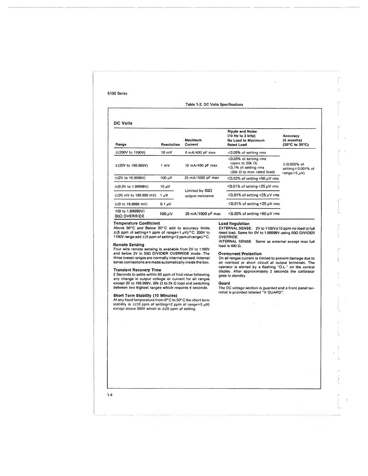
1-24, Complete Specifications
1-25. The complete specifications for the 5100 Series
Calibrators are listed in Tables 1-2 through 1-7, with each
table covering aspecific portion of the specifications.
Refer to Table 1-2 for detailed listings on DC Volts;
Table 1-3 for AC Volts; Table 1-4 for Current, both direct
and alternating; Table 1-5 for Resistance; Table 1-6 for
the Wideband Option -03; and Table 1-7 for the General
Specifications, including environmental information.
1-2