FLUVO rio Air bubbler User manual

rio Air bubbler
GB
27103 - C
Translation of the original
Operator’s Manual


CONTENTS
3rio Luftsprudler
Version: 27103 - C
Schmalenberger GmbH + Co. KG
D-72072 Tübingen / Germany
Contents
1General / Usage Instructions.......................................................... 4
1.1 Guarantee notice ........................................................................................... 4
1.2 General .......................................................................................................... 4
1.3 Usage Instructions ......................................................................................... 4
2Safety Instructions .......................................................................... 4
2.1 Safety Instructions for the Operator............................................................... 4
3Unit Description / General Technical Data.................................... 5
3.1 Technical Data............................................................................................... 5
4rio Air bubbler.................................................................................. 5
4.1 Shuttering / Concrete-tile pool and Concrete-liner pool................................. 5
4.2 Shuttering removal / Concrete-tile pool and Concrete-liner pool ....................6
4.3 Installation / Concrete-tile pool....................................................................... 6
4.4 Installation / Concrete-liner pool ................................................................... 7
4.5 Installation / Pre-fabricated pool .................................................................... 8
4.6 Pipework Diagram.......................................................................................... 9
5Spare parts list rio Air bubbler....................................................... 10
5.1 Concrete-tile pool........................................................................................... 10
5.2 Concrete-liner pool......................................................................................... 11
5.3 Pre-fabricated pool......................................................................................... 12

4rio Luftsprudler
Version:27103 - C
Schmalenberger GmbH + Co. KG
D-72072 Tübingen / Germany
1 General / Usage Instructions
1.1 Guarantee notice
If the instructions contained in this operator’s manual are not observed then any claims un-
der guarantee shall be void.
1.2 General
All parts coming into contact with media are designed for water quality to DIN 19643.
The rio Air bubbler is of state-of-the-art technology and was manufactured with great care
under constant quality control conditions.
The operator’s manual contains important instructions on how to use the rio Air bubbler
safely, properly and economically. The instructions must be strictly adhered to in order to
avoid danger and to ensure that the Air bubbler system has a long useful life.
This manual does not take into account local regulations, the observance of which is the
responsibility of the operator – also on behalf of installation personnel that may be invol-
ved.
1.3 Usage Instructions
Neither the entire unit nor parts thereof must be used in other systems. You are expressly
directed to use it only in accordance with these instructions.
Under no circumstances must the rio Air bubbler be used in a way that exceeds the figures
quoted in the technical specification. In case of doubt, please contact your customer ser-
vice or the manufacturer.
2 Safety Instructions
Please read this operator’s manual carefully before you install and operate the rio Air bubb-
ler. Make sure that you have understood everything.
2.1 Safety Instructions for the Operator
1. Regardless of what nature they may be, repairs must only be carried out by qualified
persons. If necessary, the pool should be emptied.
2. The operator must ensure that
- the operator’s manual is always available for users to read,
- instructions in the operator’s manual are being observed.
3. All parts that come into contact with the medium are resistant to an absolute salt con-
tent of up to 0,75% (4500mg/l Cl¯). If the salt concentrations are greater than this, the
manufacturer must be consulted.
5rio Luftsprudler
Version: 27103 - C
Schmalenberger GmbH + Co. KG
D-72072 Tübingen / Germany
3 Unit Description / General Technical Data
The system complies with VDE (Association for Electrical, Electronic & Information
Technologies) regulations.
The rio Air bubbler is delivered as 3 assemblies:
I Installation kit
II Assembly kit
III Blower installation kit
3.1 Technical Data
4 rio Air bubbler
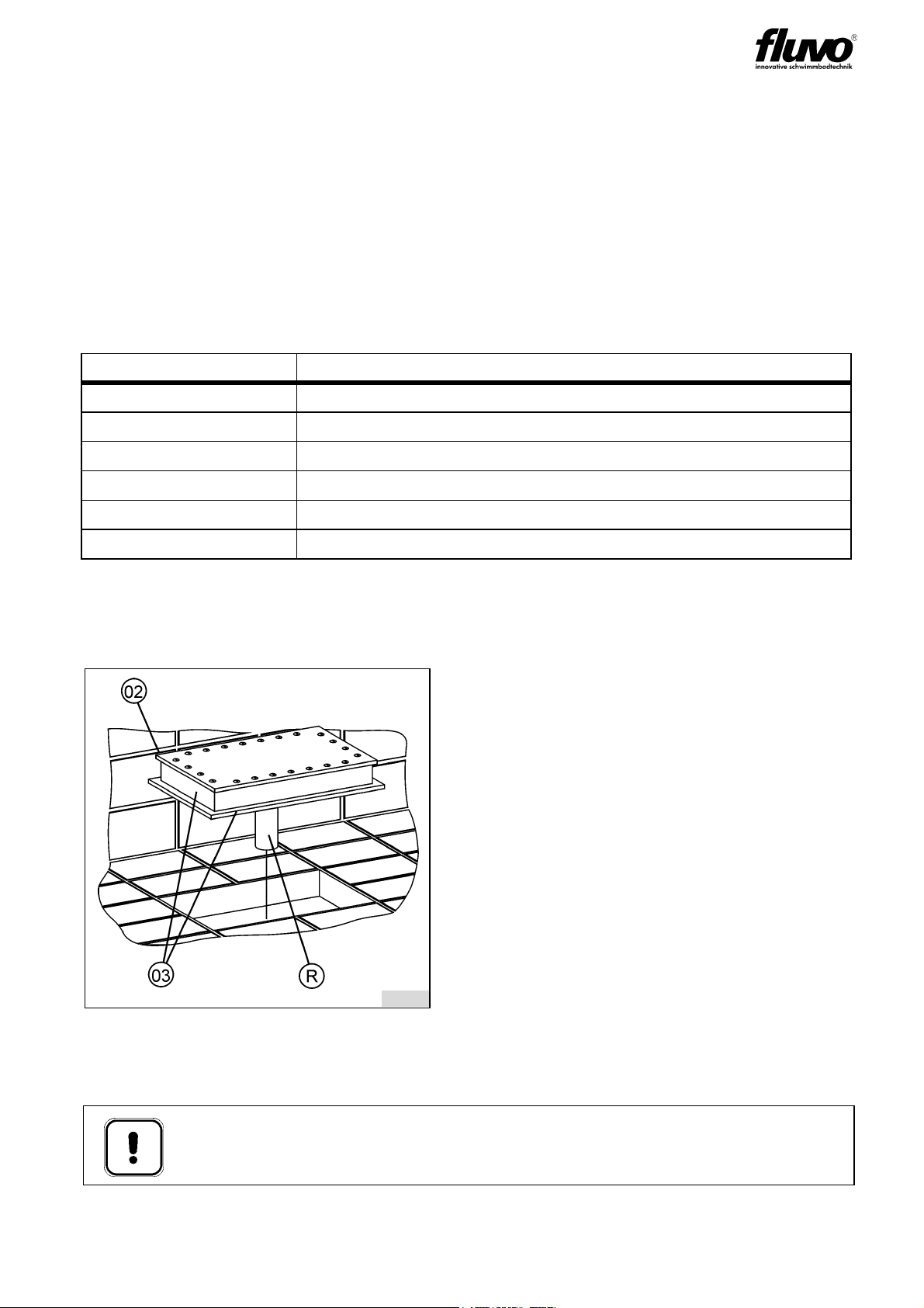
4.1 Shuttering / Concrete-tile pool and Concrete-liner pool
Establish the centre of the air pad (with respect to the tile grid) precisely.
Drill the floor shuttering in the desired place for the pressure pipe (R) d = 40mm.
rio Air bubbler
Dimensions in mm 250 x 500
Material ABS/PVC
Air connection DN 32
Air flow rate 60 m³/h
Operating pressure 150 mbar
Max. perm. pressure 250 mbar
fig. 1
R Pressure pipe
02 Cover plate
03 Installation kit
Important:
Adjust the edges of the installation kit (03) exactly (along the tile grid).
A correction later is not possible!
8106
6rio Luftsprudler
Version:27103 - C
Schmalenberger GmbH + Co. KG
D-72072 Tübingen / Germany
The upper edge of the cover plate (02) must be flush with the raw concrete.
Fasten the installation kit (03) to the concrete reinforcing bars in this position.
4.2 Shuttering removal / Concrete-tile pool and Concrete-liner pool
see fig. 1
Once the shuttering has been removed the cover plate (02) is removed from the installation
kit (03).
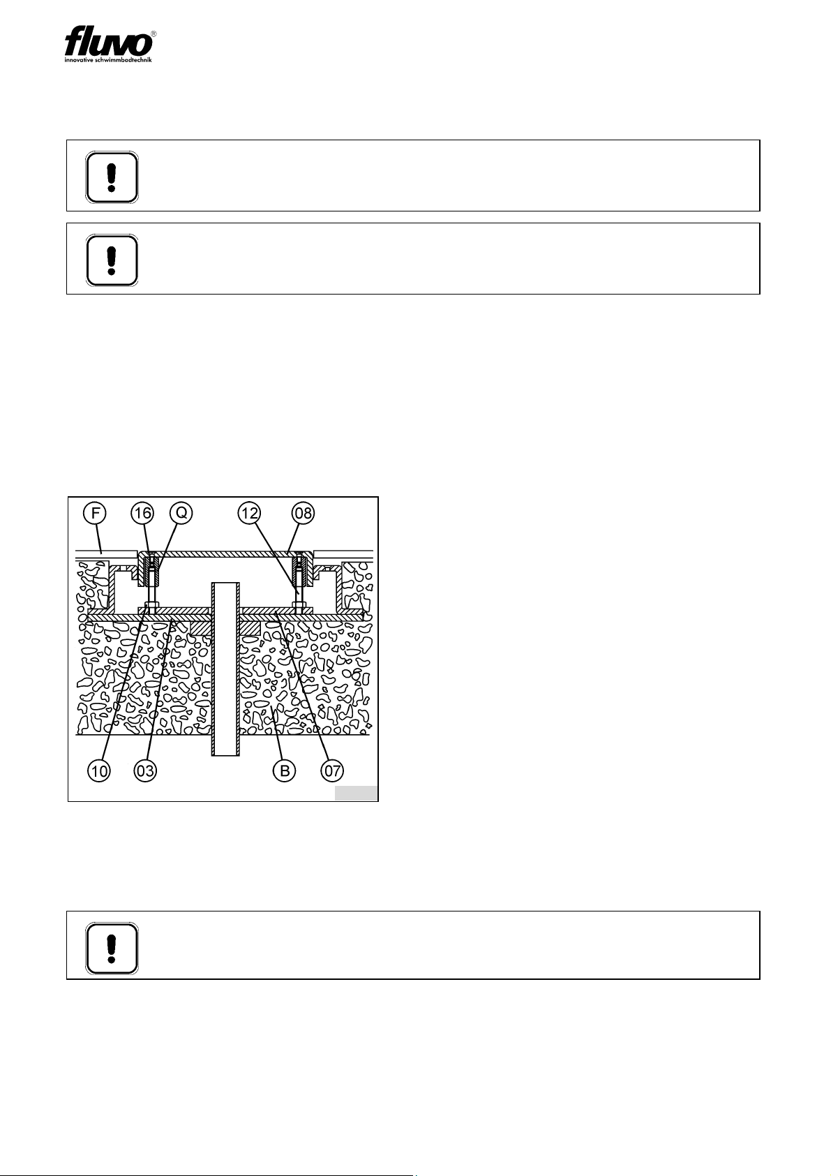
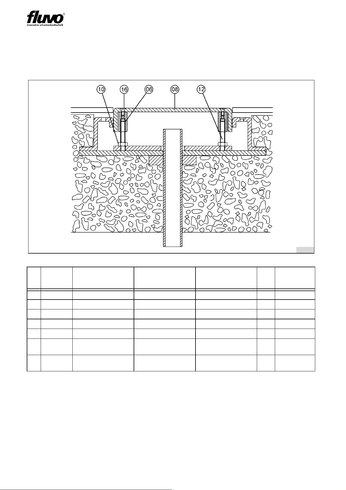
4.3 Installation / Concrete-tile pool
Screw together the air pad using the adjusting nuts (Q) and threaded rods (12) provided.
Then adjust to the level of the tiles, screw into the assembly plate (07) and fasten with lock
nuts (10).
After checking the installation level, paint the assembly plate (07) with PVC glue and stick
into the installation kit (03).
Set the adjusting nuts (Q) so that the upper surface of the air pad (08) is flush with the up-
per edge of the tiles and screw it in place into the PVC assembly frame (07). Then check
Important:
Before the concrete is poured the installation kit (03) must be fitted horizontally
and true to dimensions in such a way that it cannot move.
Important:
For mosaic tiles the ABS installation kit (03) must be pre-treated. For more de-
tails please contact the manufacturer.
fig. 2
B Raw concrete
FTiles
Q Adjusting nut
03 Installation kit
07 Assembly plate
08 Air pad
10 Lock nut
12 Threaded rod
16 Mounting screw
Important:
Watch for the level of the pool floor and the tiles!
8107
7rio Luftsprudler
Version: 27103 - C
Schmalenberger GmbH + Co. KG
D-72072 Tübingen / Germany
the installation level by putting the air pad (08) in place.
Lock the adjusting nuts (Q) with lock nuts (10) and fasten the air pad (08) to the adjusting
nuts (Q) with the screws (16).
In tiling up to the air pad (08) please watch the expansion gap.
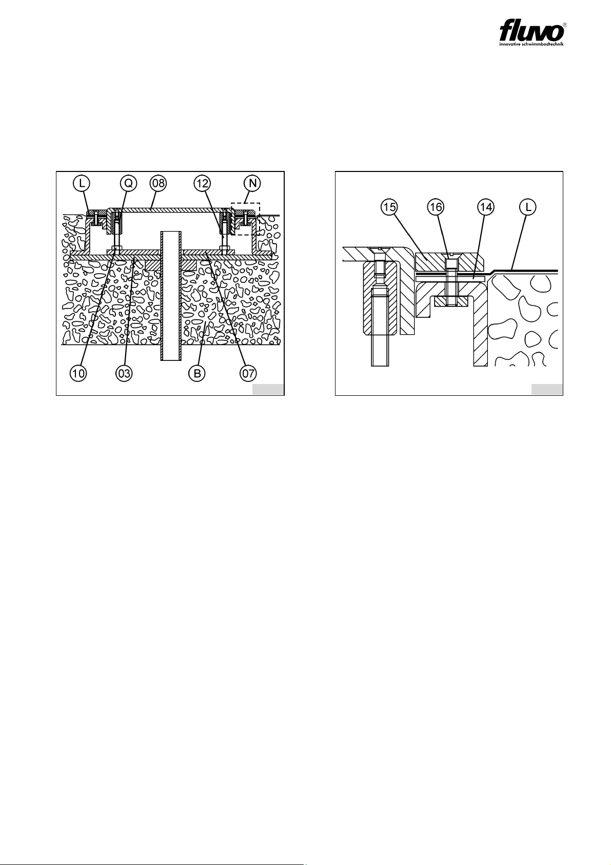
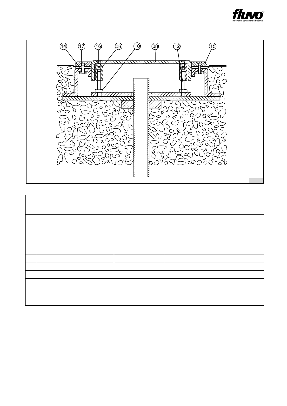
4.4 Installation / Concrete-liner pool
Lay the clamp gasket (14) between the installation kit (03) and the liner (L). Then place the
clamp ring (15) on the liner (L) and fasten with the mounting screws (16).
Screw together the air bubbler using the adjusting nuts (Q) and threaded rods (12) provi-
ded.
Then adjust to the level of the clamp ring (15), screw into the assembly plate (07) and fa-
sten with lock nuts (10).
After checking the installation level, paint the assembly plate (07) with PVC glue and stick
into the installation kit (03).
fig. 3 fig. 4: detail N
B Raw concrete
L Liner
Q Adjusting nut
03 Installation kit
07 Assembly plate
08 Air pad
10 Lock nut
12 Threaded rod
14 Clamp gasket
15 Clamp ring
16 Mounting screw
8108 8109

8rio Luftsprudler
Version:27103 - C
Schmalenberger GmbH + Co. KG
D-72072 Tübingen / Germany
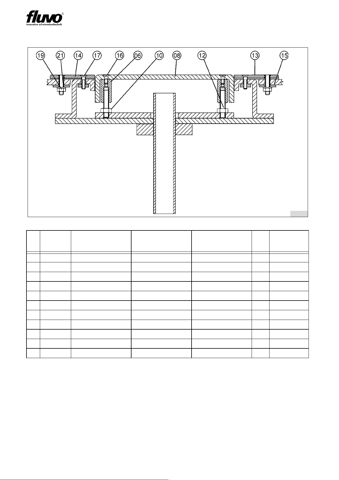
4.5 Installation / Pre-fabricated pool
Cut a rectangular section measuring 340mm x 590mm out of the pool wall. With the help
of the template, drill holes with d = 9mm for the stay bolts (G).
Lay the clamp gasket (14) on top, place the stay bolts (G) with the holding flange (15) into
the holes provided and fasten to the pool wall (A).
Fasten the installation kit (03) to the clamp ring (13). Screw together the air pad (08) using
the adjusting nuts (Q) and threaded rods (12) provided. Then adjust to the level of the
clamp ring (13), screw into the assembly plate (07) and fasten with lock nuts (10).
After checking the installation level, paint the assembly plate (07) with PVC glue and stick
into the installation kit (03).
fig. 5
A Pre-fabricated pool
GStaybolt
Q Adjusting nut
03 Installation kit
07 Assembly plate
08 Air pad
10 Lock nut
12 Threaded rod
13 Clamp ring
14 Clamp gasket
15 Holding flange
8110
9rio Luftsprudler
Version: 27103 - C
Schmalenberger GmbH + Co. KG
D-72072 Tübingen / Germany
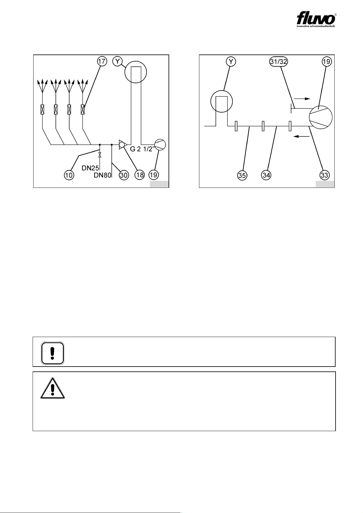
4.6 Pipework Diagram
fig. 6: Suggestion for the rio bubbler
250mmx500mm
(4 connections in a row)
Delivery rate
per connection: 60m³/h
fig. 7: When blower accessories are
fitted (schematic diagram)
10 Drain pipe
17 Shut-off unit
18 Non-return valve
19 Blower, P = 2.9 kW
30 Fresh water pipe
Y Air loop
(this must be placed a minimum of
0.5m above the surface of the wa-
ter)
9 Blower
31/32 Fine filter / muffler
33 Heat-resistant pipe
34 Intermediate piece (only for instal-
lation of 31/32)
35 Pressure control valve
Y Air loop
(this must be placed a minimum of
0.5m above the surface of the wa-
ter).
Important:
The suggested pipework diagram takes no account of actual local conditions.
Attention!
To determine the exact dimensions of the pipes all elements that contribute to
the flow must be taken into consideration.
Most importantly no 90° T-pieces or angles must be employed. Furthermore all
shut-off devices such as flaps or sliders as well as measuring detectors etc.
must be included in the flow reduction calculation.
8084 8085
Ersatzteilliste / Liste des pièce detachées / Spare parts list
10rio Luftsprudler
Version:27103 - C
Schmalenberger GmbH + Co. KG
D-72072 Tübingen / Germany
5 Ersatzteilliste rio Luftsprudler /
Liste des pièces detachées rio Bain bouillonnant /
Spare parts list rio Air bubbler
5.1 Betonbecken gefliest / Bassin béton-carrelage / Concrete-tile pool
Abb. 8
Pos. Best. Nr.
No. de réf.
Order No.
Bezeichnung Désignation Description Stck.
Nbre.
Qty.
Bemerkung
Remarque
Remark
06 53723 Stellmutter Ecrou de serrage Adjusting nut 6
08 57722 Luftsprudelplatte Plaque à bulles Bubbler 1
10 12192 Kontermutter Contre-écrou Lock nut 6 M 10
12 10233 Gewindestange Tige filetée Threaded rod 6 M 10
16 10142 Befestigungsschraube Vis de fixation Mounting screw 6 M 6
93937 Einbausatz komplett Pìèce à sceller
complète
Installation kit complete 1
93939 Fertigmontage
komplett
Kit de montage
complet
Assembly kit
complete
1
8111
Ersatzteilliste / Liste des pièce detachées / Spare parts list
11rio Luftsprudler
Version: 27103 - C
Schmalenberger GmbH + Co. KG
D-72072 Tübingen / Germany
5.2 Betonbecken mit Folie / Bassin béton-liner / Concrete-liner pool
Abb. 9
Pos. Best. Nr.
No. de réf.
Order No.
Bezeichnung Désignation Description Stck.
Nbre.
Qty.
Bemerkung
Remarque
Remark
06 55723 Stellmutter Ecrou de serrage Adjusting nut 6
08 57722 Luftsprudelplatte Plaque à bulles Bubbler 1
10 12192 Kontermutter Contre-écrou Lock nut 6 M 10
12 10233 Gewindestange Tige filetée Threaded rod 6 M 10
14 22243 Flachdichtung Joint plat Clamp gasket 1
15 59023 Klemmring Bague de serrage Clamp ring 1
16 10142 Befestigungsschraube Vis de fixation Mounting screw 6 M 6
17 10147 Befestigungsschraube Vis de fixation Mounting screw 40 M 8
93938 Einbausatz komplett Pièce à sceller
complète
Installation kit complete 1
93950 Fertigmontage
komplett
Kit de montage
complet
Assembly kit
complete
1
8112
Ersatzteilliste / Liste des pièce detachées / Spare parts list
1 2rio Luftsprudler
Version:27103 - C
Schmalenberger GmbH + Co. KG
D-72072 Tübingen / Germany
5.3 Fertigbecken / Bassin préfabriqué / Pre-fabricated pool
Abb. 10
Pos. Best. Nr.
No. de réf.
Order No.
Bezeichnung Désignation Description Stck.
Nbre.
Qty.
Bemerkung
Remarque
Remark
06 55723 Stellmutter Ecrou de serrage Adjusting nut 6
08 57722 Luftsprudelplatte Plaque à bulles Bubbler 1
10 12192 Kontermutter Contre-écrou Lock nut 6 M 10
12 10233 Gewindestange Tige filetée Threaded rod 6 M 10
13 59022 Klemmring Bague de serrage Clamp ring 1
14 22233 Flachdichtung Joint plat Clamp gasket 1
15 59014 Haltering Bague de retenue Hold-ring 1
16 10142 Befestigungsschraube Vis de fixation Mounting screw 6 M 6
17 10147 Befestigungsschraube Vis de fixation Mounting screw 40 M 8
19 12181 Mutter Ecrou Nut 40 M 8
21 12392 Unterlegscheibe Rondelle Distance washer 1
8113

Schmalenberger GmbH + Co. KG
D-72072 Tübingen / Germany

Schmalenberger GmbH + Co. KG
D-72072 Tübingen / Germany

Schmalenberger GmbH + Co. KG
D-72072 Tübingen / Germany

Schmalenberger GmbH + Co. KG Telefon: +49 (0)7071 70 08 - 0
Strömungstechnologie Telefax: +49 (0)7071 70 08 - 10
Im Schelmen 9 - 11 Internet: www.fluvo.de
© 2018 Schmalenberger GmbH + Co. KG ; All rights reserved
This document is subject to change without notice
Table of contents
Other FLUVO Lighting Equipment manuals


Popular Lighting Equipment manuals by other brands


Velleman
Velleman HQ POWER ARAS 45W user manual

IDEAL INDUSTRIES
IDEAL INDUSTRIES CREE LIGHTING 304 Series installation instructions

Rollei
Rollei Lumen Pro RGB 50 W / 100 W manual

Fusion
Fusion 25535 Assembly instructions

Hamron
Hamron 010934 operating instructions

Sentiotec
Sentiotec ProD DMX Instructions for installation and use


