FLUVO XANAS 1.5 User manual

27263 - A.1
Operator’s Manual / assembly instructions
Translation of the original
GB
XANAS®Electrical Installation

2XANAS Electrical Installation
Version: 27263 - A.1
Schmalenberger GmbH + Co. KG
D-72072 Tübingen / Germany
Table of contents
1 General information ............................................................................... 3
1.1 Warranty notice .....................................................................................................3
1.2 General information ...............................................................................................3
1.3 Proper use .............................................................................................................3
2 Safety Instructions ................................................................................. 4
2.1 General information ...............................................................................................4
2.2 Marking ..................................................................................................................4
2.3 Safety instructions for the operator ........................................................................5
3 Description of the device / general technical data .............................. 6
3.1 Technical data for pump kit (sample selection) .....................................................6
3.2 Technical design of pump kit .................................................................................7
3.2.1 Manually controlled design ....................................................................................................7
3.2.2 Sensor-controlled design .......................................................................................................7
3.3 "Manually controlled design" modules ...................................................................8
3.3.1 Control unit ............................................................................................................................8
3.3.2 Control box NT .......................................................................................................................9
3.3.3 Pump type WK .....................................................................................................................10
3.3.4 Connection diagrams - Manually controlled design ...........................................................11
3.3.5 Operation - Manually controlled design ...............................................................................12
3.4 "Sensor-controlled design" modules ....................................................................13
3.4.1 Control unit ..........................................................................................................................13
3.4.2 Converter box ......................................................................................................................14
3.4.3 Pump type WK-FU ...............................................................................................................15
3.4.4 FU programming - XANAS® specific delivery state .............................................................15
3.4.4.1 Operating modes: ................................................................................................................16
3.4.4.2 "Internal potentiometer" operating mode .............................................................................17
3.4.4.3 "Analog control" operating mode .........................................................................................17
3.4.4.4 Additional feedback contacts ...............................................................................................18
3.4.4.5 Error message on FU ..........................................................................................................18
3.4.5 Connection diagrams - Sensor-controlled design ..............................................................19
3.4.5.1 Testing the wiring .................................................................................................................20
3.4.6 Connection for external operation ........................................................................................20
3.4.7 Operation - Sensor-controlled design ..................................................................................21
3.5 Installation instructions for sensor button and control unit ...................................22

3
XANAS Electrical Installation
Version: 27263 - A.1 Schmalenberger GmbH + Co. KG
D-72072 Tübingen / Germany
1 General information
1.1 Warranty notice
1.2 General information
All parts in contact with media are designed for water quality according to DIN 19643.
This counter-current system (XANAS®) represents the state of the art. It has been manu-
factured with the greatest care and is subject to continuous quality control.
This Operator’s Manual contains important information to ensure that the counter-current
system is operated safely, properly and economically.
Your strict observance is necessary to prevent dangers and ensure a long service life for
the counter-current system.
This operator's manual does not take into consideration local requirements. The operator
is responsible for ensuring these requirements are met, including personnel retained to
assemble the system.
The rating plate indicates the series and frame size, the most important operating data and
the factory number. If additional information is required, please always specify it when reor-
dering or ordering spare parts.
1.3 Proper use
The counter-current system was designed for use in private swimming pools.
Therefore it should not be installed in public swimming pools. The counter-current system
must not be operated beyond the values specified in technical data (3.1). If you have any
questions, please contact your Customer Service representative or the manufacturer.
The entire system or parts of it are not suitable for use in other systems. The
function of the entire system in combination with other systems or components
can not be guaranteed. Accordingly we explicitly instruct you only to use such
parts or the entire system for their intended purpose.
Failure to comply with the information provided in this operator's manual voids
all claims under warrantee.

4XANAS Electrical Installation
Version: 27263 - A.1
Schmalenberger GmbH + Co. KG
D-72072 Tübingen / Germany
2 Safety Instructions
2.1 General information
• Make certain before commissioning that the operating personnel have read and under-
stood the operator's manual. It is the owner rather than the operator who is responsible
for safety.
• Make certain the safety requirements and laws for the use of counter-current systems
which apply to the operating company and/or country in which the system is operated
are observed.
• Use the counter-current system only when it is in flawless condition technically and ac-
cording to its intended purpose. Be conscious of safety and dangers and observe all
the instructions of this Operator’s Manual!
• Eliminate all malfunctions that could have a detrimental effect on safety immediately.
• Before making repairs to the counter-current system, disconnect it from its electrical
power source and prevent it from being turned on again.
• Repairs of any nature must only be made by qualified specialists. The counter-current
system must also be emptied.
• The operator must ensure that:
- the operator's manual is always available for operating personnel,
- the instructions in the operator's manual are observed,
- the counter-current system is stopped immediately if any abnormal electrical volt-
ages, vibrations, temperatures, noises, vibrations, leaks, or other faults occur.
• All personsinvolvedinsetting up, commissioning, operating, maintaining, and repairing
this device must:
- consider the operator's manual to be part of the product,
- keep the operator's manual in a safe place throughout the service life of the prod-
uct,
- forward the operator's manual to each successive owner or user of the product,
- ensure that all additions that are received are inserted into the operator's manual,
- observe all legal requirements.
2.2 Marking
The following symbols are used in this operator's manual to make special reference to dan-
gers.
Notices placed directly on the pump, such as the arrow for direction of rotation, must
always be observed and must be maintained in legible condition.
Caution! Risk of injury! / Attention! Risk of damage!
This symbol warns of hazards due to mechanical effects and of actions
that will damage the product.
Caution! Danger of death!
This symbol warns you of dangers due to electrical current.

5
XANAS Electrical Installation
Version: 27263 - A.1 Schmalenberger GmbH + Co. KG
D-72072 Tübingen / Germany
2.3 Safety instructions for the operator
Electrical equipment must only be installed and serviced by qualified personnel.
Applicable safety regulations and equipment requirements at the installation site must be
observed.
The term qualified specialist (Fachkraft) is defined in VDE 0105 and IEC 364. This opera-
tor's manual does not contain any information for non-qualified persons. We explicitly draw
to your attention that the stipulations of the EC prohibit the use of non-qualified persons on
electrical systems.
• If serious operating problems occur, disconnect the system from the electrical power
source.
• Check the device and the electrical power line at regular intervals for damage.
• The L/N/PE connection of the power supply voltage must be made in accordance with
VDE 0100 and VDE 0160.
• A protective and isolating device must be provided for turning off the power supply volt-
age.
In case of damage caused by failure to observe the information provided in these
operator's manual, all claims under warranty shall be void. The manufacturer cannot
accept any liability for resulting consequential damages.
Attention:
• Failure to observe the safety instructions, for example touching live parts while the de-
vice is open or handling the device in an improper manner is hazardous with potentially
fatal consequences.
• If the guarantee seal is destroyed, the guarantee and manufacturer's warranty shall be
rendered null and void.
• If the values listed in the technical data are exceeded there is danger of the device
overheating, which can destroy the power supply and adversely affect electrical safety.
Danger of lethal electrical current!
Electrical connections must only be made by a professional electrician in
accordance with VDE Regulation 0100. Observe the local requirements of the
responsible electrical power provider as well as standards and safety require-
ments for electrical systems in swimming pools.
Comply with DIN EN 13451!
Note!
Comply with DIN EN 13451 in the design of the suction unit.
Important!
When installing a frequency inverter, follow the instructions in the Operator's
Manual "INVEOR Drive Controller" of the manufacturer (KOSTAL).

6XANAS Electrical Installation
Version: 27263 - A.1
Schmalenberger GmbH + Co. KG
D-72072 Tübingen / Germany
3 Description of the device / general technical data
• The counter-current system meets the requirements of the VDE regulations.
• The electric motor and pump through which water flows are electrically separated.
• The electric motor corresponds to protection type IP 55.
• The counter-current system as a whole meets the requirements of protection class I.
3.1 Technical data for pump kit (sample selection)
Definition of abbreviations used
WS - Single-phase alternating current motor (German Wechselstrommotor)
FU - Frequency inverter (German Frequenzumrichter), drive controller, speed-controlled
pump
System type: XANAS®
1.5 XANAS®
1.5 WS XANAS®
1.9 (FU) XANAS®
1.9 WS XANAS®
3.0 (FU) XANAS®
4.0 (FU)
Output 1.5 kW 1.5 kW 1.9 kW 1.9 kW 3.0 kW 4.0 kW
Mains voltage 3~ 400 V 1~ 230 V 3~ 400 V 1~ 230 V 3~ 400 V 3~ 400 V
Mains frequency 50 Hz 50 Hz 50 Hz 50 Hz 50 Hz 50 Hz
Motor voltage Y 400 V 230 V Y 400 V 230 V Y 400 V 400 V
Rated current Imax 2.9 A 9.5 A 4.1 A (4.6 A) 11.5 A 6.6 A (6.2 A) 8.5 A (7.9 A)
Speed 2900 rpm 2900 rpm (1200-) 2900
rpm 2900 rpm (1200 -) 2900
rpm (1200 -)
2900 rpm
max. pump capacity 700 l/min (42
m³/h) 700 l/min (42
m³/h) 800 l/min (48
m ³/h) 800 l/min (48
m ³/h) 1000 l/min
(60 m³/h) 1200 l/min
(72 m³/h)
max. delivery pres-
sure 1.2 bar 1.2 bar 1.4 bar 1.4 bar 1.9 bar 2.0 bar
max. water tempera-
ture 50° C
Usage limit (pump
only) 3000 mg/l Cl
expected acoustic
pressure level 65 + 2dB (A) 65 + 2dB (A) 67 + 2dB (A) 67 + 2dB (A) 70 + 2dB (A) 71 + 2dB (A)
Connections Pressure side DN 50
Suction side DN 65 Pressure side DN
65
Suction side DN
80
Weight 27.5 kg 27.5 kg 29.5 kg
(38 kg) 29.5 kg 36.5 kg
(45 kg) 43 kg
(51 kg)
Item no. PBS 98420 98421 98422
(98390) 98423 98425
(98391) 98426
(98392)

7
XANAS Electrical Installation
Version: 27263 - A.1 Schmalenberger GmbH + Co. KG
D-72072 Tübingen / Germany
3.2 Technical design of pump kit
XANAS® is available in two different control variants
a) Manually controlled design
b) Sensor-controlled design
3.2.1 Manually controlled design
3.2.2 Sensor-controlled design
The two design variants are presented separately from each other below.
Control unit
with 1 sensor button
and 2 twist grips
Control box NT Centrifugal pump WK
Control unit
with 3 sensor buttons Converter box
for the safety isolation Centrifugal pump WK
with FU

8XANAS Electrical Installation
Version: 27263 - A.1
Schmalenberger GmbH + Co. KG
D-72072 Tübingen / Germany
3.3 "Manually controlled design" modules
3.3.1 Control unit
Sensor button - connection assignment
Sensor button - technical information
See also section 3.5 "Installation instructions for sensor button and control unit"
Activation via
1 x sensor button lit
2 x twist grips
Sensor button connection cable
• 5-wire special cable
• Standard cable length 2m
• Colour coded DIN 47100
• External diameter 5.5mm
• Wire cross-section 0.5 mm²
Wire colour Functions
White Switching contact S1
Brown Switching contact 24V
Grey LED1
Yellow LED2
Green LED3
Effect of switching: Pulse activated one time
Electrical function: normally open / N/O contact
Electrical data: Imax = 200mA / UB= 24V DC
Note:
When laying cables, safe isolation between different types of currents within an
installation system must be ensured without exception. Comply with the
requirements of DIN EN 50174 and DIN VDE 0100-520 for communication wir-
ing when laying the cables.
Safety isolation
For reasons of electrical safety, the sensor button must without exception be
operated via "safety isolation" such as a control box item no. 61405 or directly
on the NT switch box. The defined maximum line lengths must also be
observed.
9
XANAS Electrical Installation
Version: 27263 - A.1 Schmalenberger GmbH + Co. KG
D-72072 Tübingen / Germany
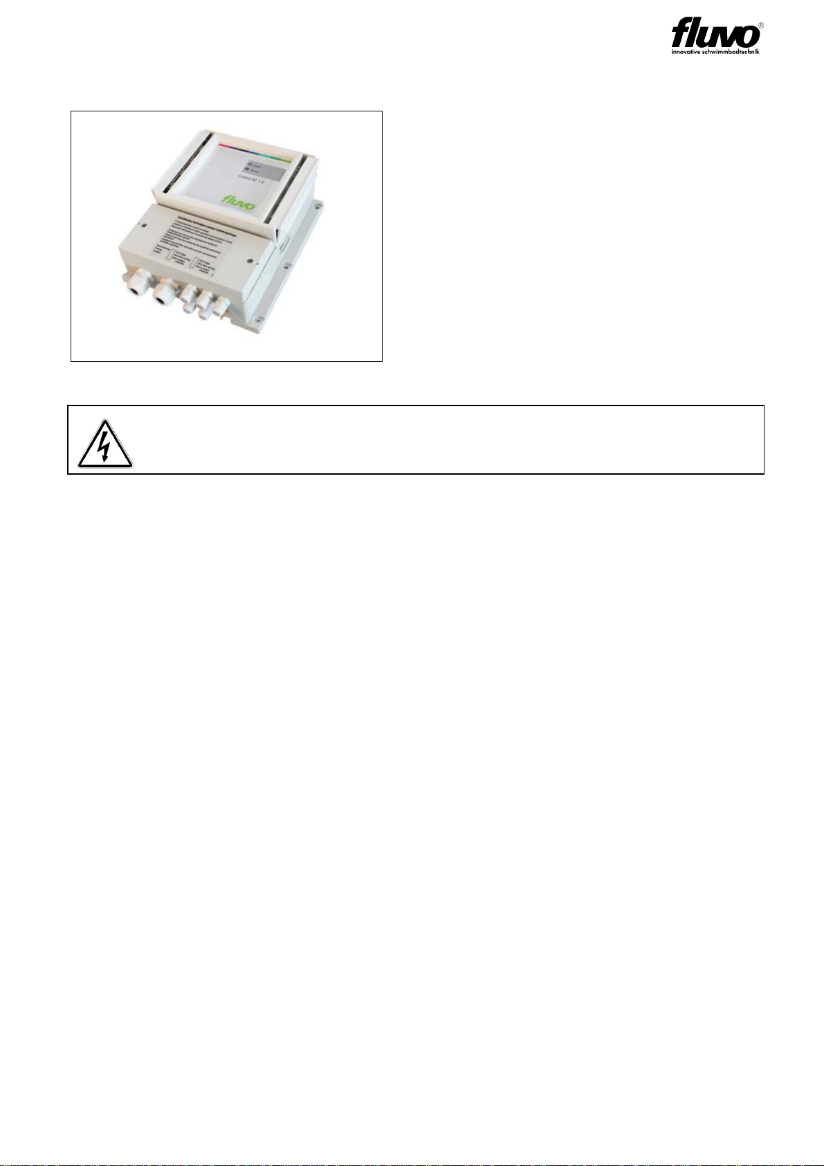
3.3.2 Control box NT
Operator's Manual 27248 "Control Box Control NT" applies
• Technical data
• Wall installation with dimensions
• Connections and settings
- Mains pump / connection terminal
- Connection terminals for control and feedback contacts
- Bus connection
- Terminal compartment disconnection
• Fault message
• Current monitoring
• 1-Phase and 3-Phase Operation
• Run time limit, time relay function
Control box NT
The control box can be used to switch a
1-phase or 3-phase pump on and off.
The sensor button is designed as an actua-
tor.
The device status is displayed by two operat-
ing LEDs with output via two floating feed-
back contacts.
The control box must always be positioned above the water level of the
pool!
10 XANAS Electrical Installation
Version: 27263 - A.1
Schmalenberger GmbH + Co. KG
D-72072 Tübingen / Germany
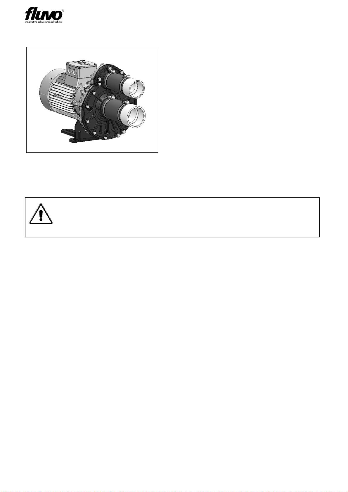
3.3.3 Pump type WK
The electrical output values between the switch box NT and centrifugal pump WK are coor-
dinated in the device kit.
Operator's Manual 27220 "Centrifugal
Pump WK" applies
• General information with data sheet for
pump WK
• Safety Instructions
• Transport and storage
• Electrical connection of the pump
• Operating the Centrifugal Pump
Check the circuit type Y / .
During installation note
- the mains voltage information on the type plate of the control box and motor
- the direction of rotation arrow on the pump
11
XANAS Electrical Installation
Version: 27263 - A.1 Schmalenberger GmbH + Co. KG
D-72072 Tübingen / Germany
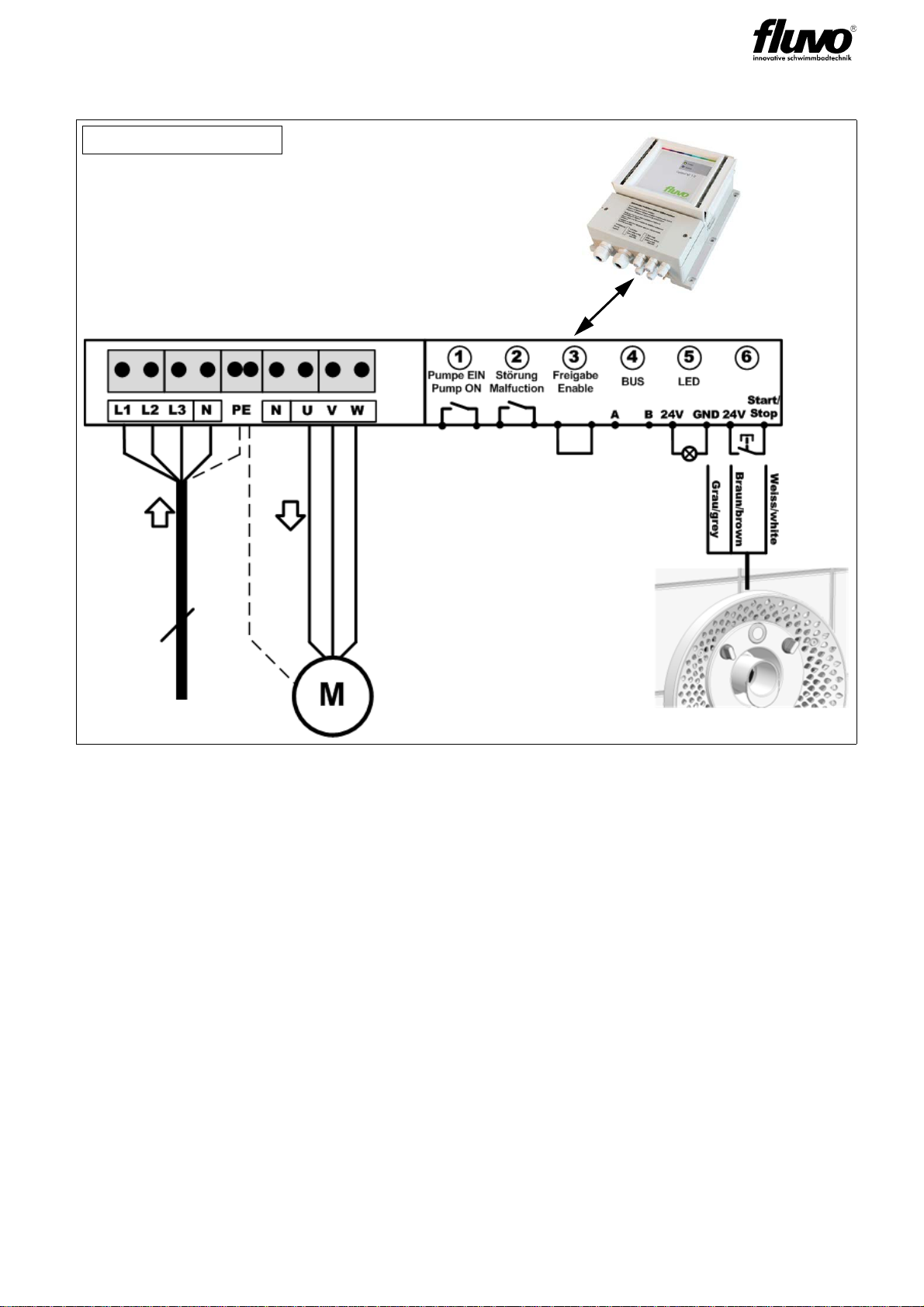
3.3.4 Connection diagrams - Manually controlled design
Range of the
connection terminals
5
Electrical power source
Example 3~ 400V

12 XANAS Electrical Installation
Version: 27263 - A.1
Schmalenberger GmbH + Co. KG
D-72072 Tübingen / Germany
3.3.5 Operation - Manually controlled design
Switching On/Off
Pressing the ON/OFF button turns the system on or off. The button is always lit and flashes
to provide visual feedback.
Regulating the intensity
ON/OFF
Water control
Air control

13
XANAS Electrical Installation
Version: 27263 - A.1 Schmalenberger GmbH + Co. KG
D-72072 Tübingen / Germany
3.4 "Sensor-controlled design" modules
3.4.1 Control unit
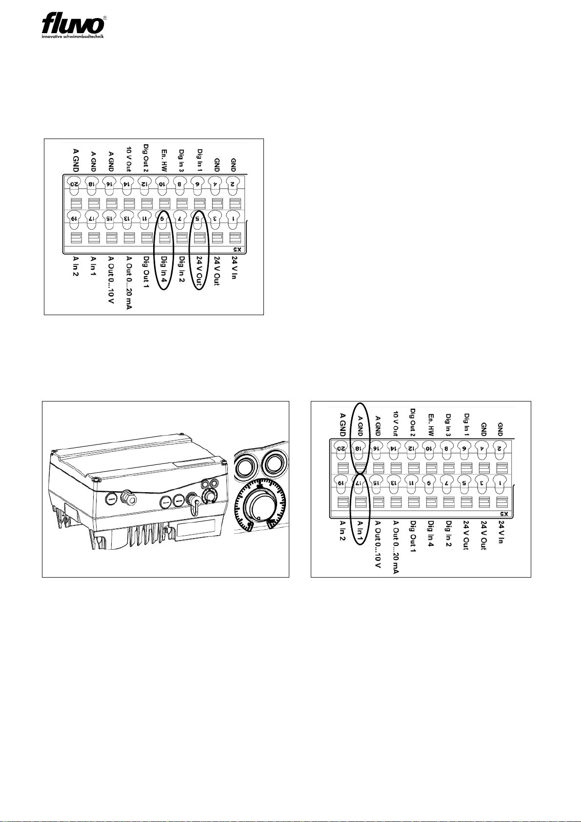
Sensor button - connection assignment
Note: Arrangement corresponds to the order of terminals in the corresponds to box
Sensor button - technical information
Activation via
1 x sensor button lit
2 x sensor buttons unlit
Sensor button connection cable
• 9-wire special cable
• Standard cable length 2m
• Colour coded DIN 47100
• External diameter 6.3mm
• Wire cross-section 0.25 mm²
Wire colour Functions
White LED1
Brown Switching contact S1
Green 24V
Yellow LED2
Grey Switching contact S2
Pink 24V
Blue LED3
Red Switching contact S3
Black 24V
Effect of switching: Pulse activated one time
Electrical function: normally open / N/O contact
Electrical data: Imax = 200mA / UB= 24V DC

14 XANAS Electrical Installation
Version: 27263 - A.1
Schmalenberger GmbH + Co. KG
D-72072 Tübingen / Germany
See also section 3.5 "Installation instructions for sensor button and control unit“
3.4.2 Converter box
Operator's Manual 27251 "Converter Box 3.0" applies
• Device overview
• Operating mode – mode 1 "THREE-button control with analog signal“
• Installation instructions and cable length
• Housing dimensions
Note:
When laying cables, safe isolation between different types of currents within an
installation system must be ensured without exception. Comply with the
requirements of DIN EN 50174 and DIN VDE 0100-520 for communication wir-
ing when laying the cables.
Safety isolation
For reasons of electrical safety, the sensor button must without exception be
operated via "safety isolation" such as a control box item no. 61405 or directly
on the NT switch box. The defined maximum line lengths must also be
observed.
The converter box 3.0 also serves as a
safety isolating element and for
evaluating button pulses of the sensor
button.
The signal output for the XANAS® is via an
analog output (AOUT).
The main task of the converter box is to
ensure a safe isolation between the sensor
buttons (buttons 1-3) on one side and the
analog and Vcc connections on the other
side of the frequency inverter. The purpose
of the converter box is to ensure safe and
reliable operation of the sensor buttons in the
swimming pool.
The converter box must always be positioned above the water level of the
pool!
15
XANAS Electrical Installation
Version: 27263 - A.1 Schmalenberger GmbH + Co. KG
D-72072 Tübingen / Germany
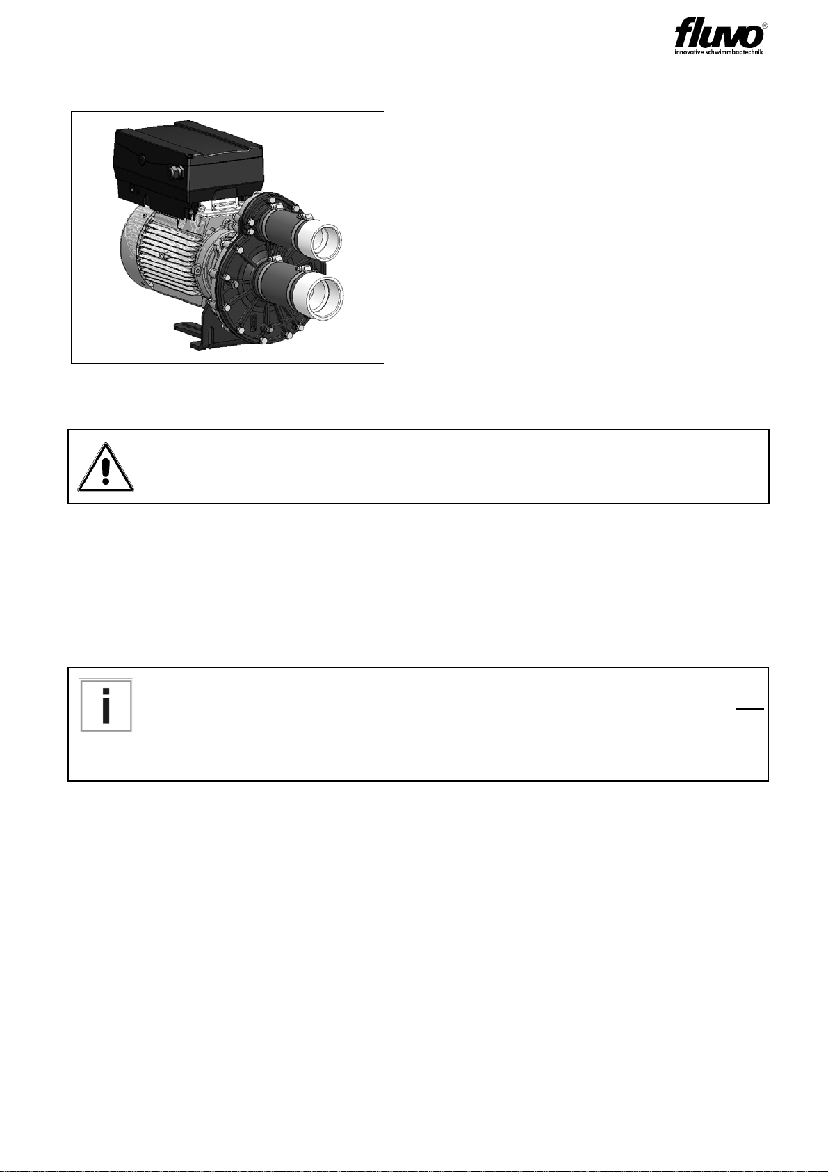
3.4.3 Pump type WK-FU
The abbreviation FU stands for the frequency inverter (German Frequenzumrichter) and
the drive controller
• General information
• Safety Instructions
• Installation
• Start-up
• Detecting and eliminating errors
• Technical data
3.4.4 FU programming - XANAS® specific delivery state
Information to supplement the INVEOR Operator's Manual
The centrifugal pump is generally delivered with the FU attached. The power data is coor-
dinated between the FU and the motor.
The FU has an active motor overcurrent protection function. The mains power connection
for the FU must be designed according to the information in the INVEOR Operator's Man-
ual (KOSTAL).
Operator's Manual 27220 "Centrifugal
Pump WK" applies
• General information with data sheet for
pump WK
• Safety Instructions
• Transport and storage
• Electrical connection of the pump
• Operating the Centrifugal Pump
Operator's Manual "INVEOR drive controller" applies
http://www.kostal-industrie-elektrik.com/de-DE/Download/Antriebs-
technik
If three-phase frequency inverters are used, conventional FI circuit breakers
type A, also called RCD (residual current-operated protective device) are not
approved for protection against direct or indirect contact!
In accordance with DIN VDE 0160 and EN 50178, the FI circuit breaker must
be a FI circuit breaker RCD type B (sensitive to all currents)!
16 XANAS Electrical Installation
Version: 27263 - A.1
Schmalenberger GmbH + Co. KG
D-72072 Tübingen / Germany
3.4.4.1 Operating modes:
The FU is delivered with two operating modes.
At the time of delivery operating mode 2 is activated via a wire jumper.
You can change between the two operating modes with DigIn4.
Operating mode 1:
Internal potentiometer Operating mode 2:
Analog control
Commissioning function XANAS® function
• Manual speed setting via rotary potenti-
ometer directly on the FU
• Control range between saved MIN / MAX
speed
• Active when DigIn4 is unassigned
• Speed setting via analog signal 0-
10V on control terminal A In1
• Control range between saved MIN /
MAX speed
• Active with jumper between DigIn4
and 24VOut
17
XANAS Electrical Installation
Version: 27263 - A.1 Schmalenberger GmbH + Co. KG
D-72072 Tübingen / Germany
3.4.4.2 "Internal potentiometer" operating mode
The FU does not start up until the hardware enable (En.HW) is set.
At the time of delivery the hardware enable (En.HW) is not set.
The FU is ready for operation when the green signal LED is flashing. Mains voltage is
applied then with the hardware enable not set. If the hardware enable is set now, the green
signal LED is lit continuously, the motor can start up and manual speed control between
MIN and MAX speed is now possible using the potentiometer on the FU.
3.4.4.3 "Analog control" operating mode
As terminals for XANAS® function
The FU does not start up until the hardware enable (En.HW) is set.
At the time of delivery the hardware enable (En.HW) is not set.
The FU is ready for operation when the green signal LED is flashing. Mains voltage is
applied then with the hardware enable not set. If the hardware enable is set now, the green
signal LED is lit continuously.
The hardware enable is set via Dout4 when the converter box is connected according to
the connection diagrams, sensor-controlled design. This Dout4 is switched together with
Aout when the Start button is pressed.
This ensures that the FU is disabled in Stop status.
The analog signal 0-10V which is present is used to control the speed between the MIN
and MAX speed value.

18 XANAS Electrical Installation
Version: 27263 - A.1
Schmalenberger GmbH + Co. KG
D-72072 Tübingen / Germany
3.4.4.4 Additional feedback contacts
Switches with "Malfunction"
Relay 1 (potential-free change) + DigiOUT1
Switches with "Operation"
Relay 2 (potential-free change) + DigiOUT2
For additional terminal assignments, please see the INVEOR Operator's Manual
Section 3.3.4 Control connections table, 4 Terminal assignment
3.4.4.5 Error message on FU
Red
LED Green
LED Status
Warning
Error
Key
LED off LED on
LED flashing LED flashing quickly
19
XANAS Electrical Installation
Version: 27263 - A.1 Schmalenberger GmbH + Co. KG
D-72072 Tübingen / Germany
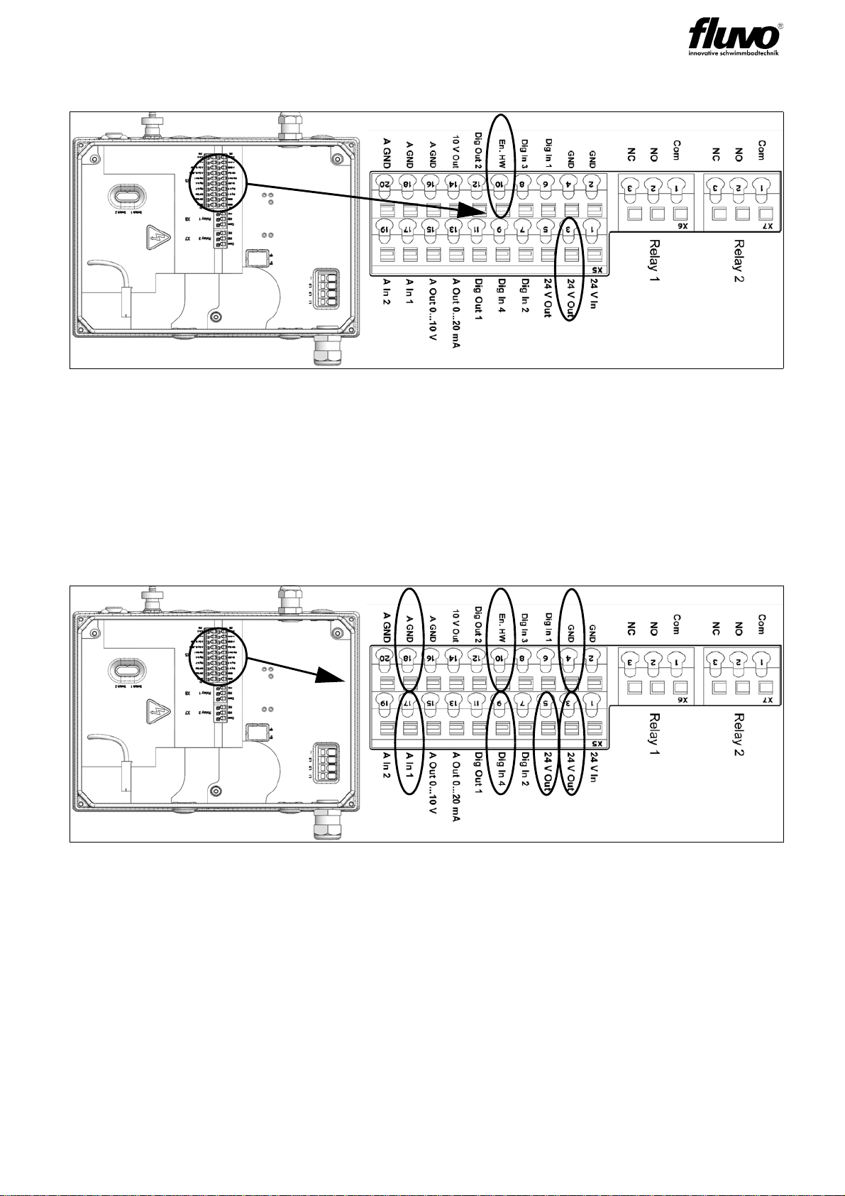
3.4.5 Connection diagrams - Sensor-controlled design
Function of XANAS® switching unit with 3 sensor buttons
Connection diagram of the switching unit with 3 sensor buttons and a 9-pin connection
cable
The button pulses (buttons 1-3) cause an incremental change to analog output
AOUT.
A lit button provides visual feedback.
When a lit button is connected, optical feedback (flashing) is generated when it is activated.
AOUT: Starting voltage 4V control range 4 / 5 / 6 / 7 / 8 / 9 / 10V
Dout4: ON when AOUT is active / ON when AOUT 0V and non-active (enable)
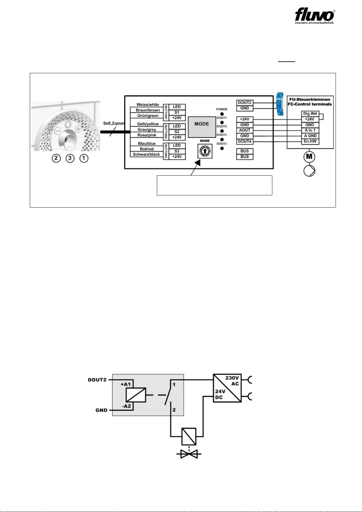
Air valve control:
If AOUT is active, a pulse combination to S2 (2 pulses within 0.5sec) causes digital output
DOUT2 to be activated.
DOUT2 can be set to inactive again with
a) S3 - System OFF
b) Pulse combination to S2 (2 pulses within 0.5sec)
Switching output of Dout2: 24V DC Imax = 20mA DC
To be able to switch an air valve with a higher electrical output, a multi-function relay item
no. 55323 can be connected to DOUT2.
FU
Converter box 3.0
Sensor button 3x
1x lit
2x unlit
Sensor button 1 incrementally falling
Sensor button 2 incrementally rising
Sensor button 3 ON / OFF
Rotary switch
MODE 1: Lit with one colour
20 XANAS Electrical Installation
Version: 27263 - A.1
Schmalenberger GmbH + Co. KG
D-72072 Tübingen / Germany
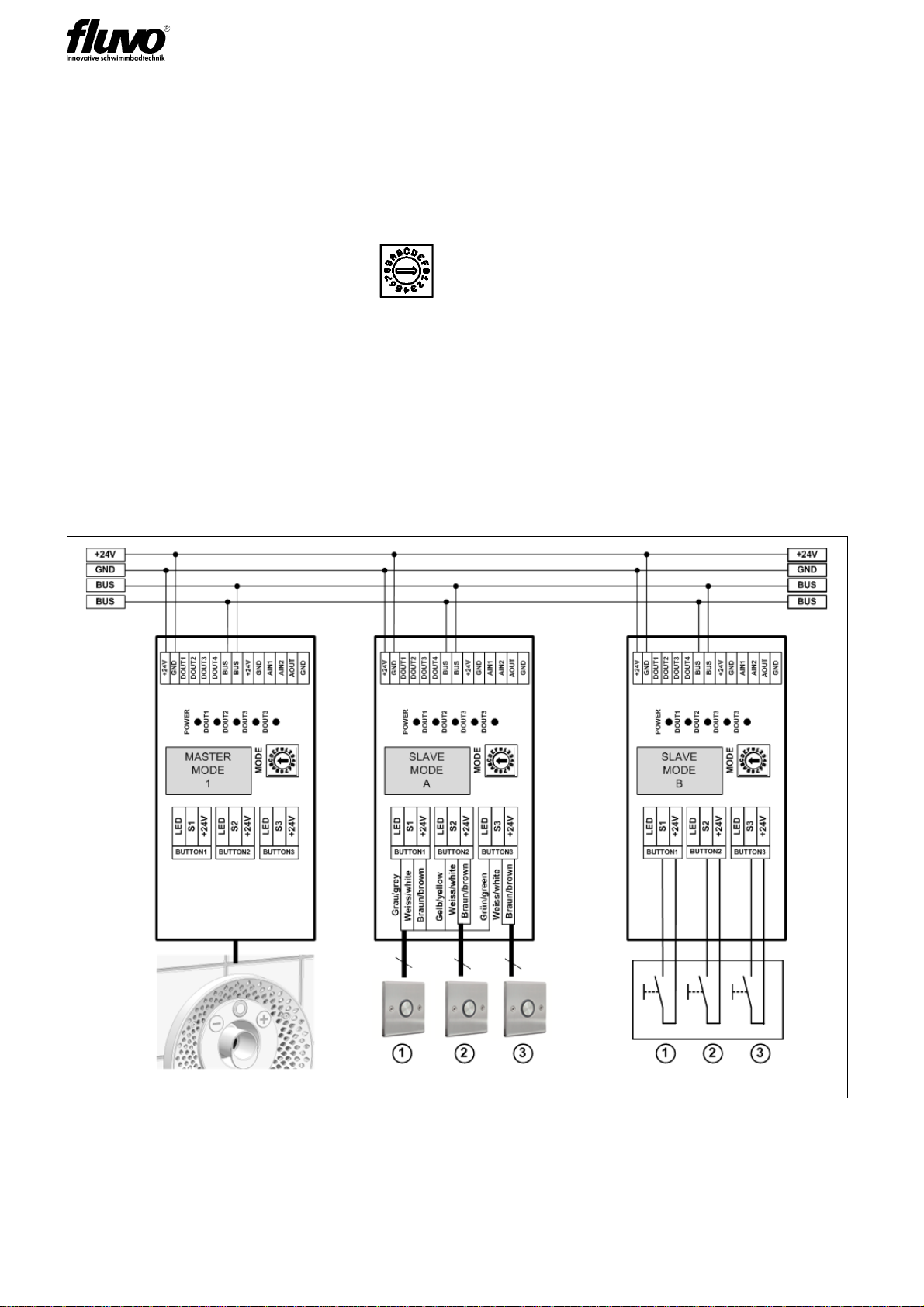
3.4.5.1 Testing the wiring
Sensor button with converter box.
1. The button pulse of the connected sensor buttons is received by the connected box
when the lit ON/OFF button indicates this visually by flashing.
2. MODE1 active via rotary switch .
Measurable signals
OFF Aout = 0V / Dout4 = 0V
ON Start status AOUT = 4 / 5 / 6 / 7 / 8 / 9 / 10V / Dout4 = 24V
Pressing the +/- key causes AOUT to change +/- 1V
Lower limit: AOUT = 4V
Upper limit: AOUT = 10V
Reaching the lower and upper limit is indicated by the button flashing several times.
3.4.6 Connection for external operation
Optional: Customer connection
This manual suits for next models
8
Table of contents
Other FLUVO Lighting Equipment manuals


